1
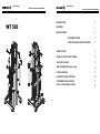
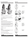
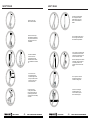
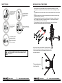
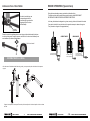
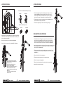
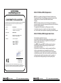
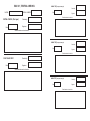
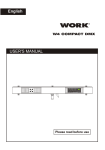
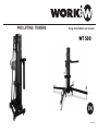
PRO LIFTING TOWERS
Using & installation user manual
WT 500
EN
Rev. 12.6.1
WT 500 LIFTER
WT 500 LIFTER
USING & INSTALLATION USER MANUAL
WT 500
USING & INSTALLATION USER MANUAL
INTRODUCTION
1
FEATURES
2
SPECIFICATIONS
2
FASTENER SYSTEM
3
(VER.12.04) NEW BLOCKING SYSTEM
3
SAFETY RULES
4
INSTALLING THE LIFTING TOWER
8
PLACING THE LOAD
9
WINCH OPERATION (Special Care)
10
LIFTING PROCESS
11
DESCENT/FOLDING PROCESS
12
CONFORMITY DECLARATION
13
BGV C1, EXPLANATION & TEST
14
INTRODUCTION
SPECIFICATIONS
WT 500 is a lifting tower for LINE ARRAY systems composed of 4 extensible aluminium reinforced sections.
This new profile system can elevate heavy loads (270 kg) at high altitude (5.98 m). Making it very suitable for
all types of events. The ground reinforcement system has been thoroughly studied, giving the tower legs
subjection of great length and stabilizing slopes. The Line Array bracket system has been strengthened taking
into account the force exerted and the thickness of metal walls and clamping rings have been increased by
incorporating angled finish allows support equitable loads.
MAX
WT 500
MIN
LOAD
LOAD
(KG)
(KG)
270
30
As usual in WORK products, all components have been oversized with the goal of achieving a superior security:
COMPOS.
(GALVANIZED)
- Strong security cable made of steel under DIN
standard.
- Exclusive blocking system with high resistance and
able to ensure the whole firmness.
- Autoblocking system.
- Additional profile blocking system when
transporting.
- Bubble level indicator vial.
- 2 iron braces placed in the back side for
additional reinforcement.
FEATURES
Upper reinforcing piece
in each section to
avoid deformations with
high loads.
WT 500
7 x 19+1
UNFOLDED LIFTER
HEIGHT
(M)
Ø
(mm)
7
5,98
BASE
(M)
1,93 x 1,75
CABLE
RESIST.
LOAD
(N / mm2) (KN - KP)
1770
MODEL
STANDARDS & REGULATIONS
WT 500
DIN 15020 / VGB 1 / VGB 8
FOLDED LIFTER
HEIGHT
(M)
28.8 - 2930
1,96
BASE
(M)
WEIGHT
(KG)
0,55 x 0,56
152
WINCH
WEIGHT/Mt ROLL.
(KG/M)
0,187
CROSSED
TO
RIGHT
BOBBING
CAPACITY
(M.)
48
REDUCT.
RANGE
3.75 : 1
FASTENER SYSTEM
Double blocking
system:
- For transportation
(upper pin bolt )
- Folfing/unfolding
(lower pin bolt).
Iron braces placed in the back
side for additional reinforcement.
This system uses a profile especially
designed to heavy loads. the width of
these profiles and the wall thickness,
ensure a great firmness of the assembly.
They incorporate a lane with fixing holes
which houses safety pins. these holes
are large enough so that the pins
introduced easily and quickly providing
a fast deployment of the tower.
The pulley system (which raised or lowered each profile), is
responsible for transmitting the stress generated in the winch
and raise each section, for this reason, these pulleys have a
proper design to handle the wire, covering the entire system
in a compact assembly.
Soporte horizontal para elevar la carga acoplada.
WT 500 LIFTER
Safety pins have been oversized,
both in diameter as the piston as
the main safety part. the lock/unlock
system is performed exerting a
small flip and rotate, allowing this
operation so simple and complete
security.
-1-
USING & INSTALLATION USER MANUAL
WT 500 LIFTER
-2-
USING & INSTALLATION USER MANUAL
SAFETY RULES
(VER. 12.04) NEW BLOCKING SYSTEM
Do not elevate the tower
without using the stabilize
legs.
B
A
3
2
1
Place the tower over a flat
and stable surface.
Do not install it in a place
where the use over the
stabilize leg would not
be enough to reach a
perfect balance.
INTRODUCTION
New V.1204 blocking systerm applied to WT 500 & LW 476 R, incorporates two security blocking systems.
The first system (marked as A) allows to block the profiles to transport or block a profile individually.
The second system (marked as B) is and automatic trigger, unblocking it, allowing to deploy or undeploy the
profile, blocking it in the prefixed fixation position.
The two largest legs
must be placed in the
frontal tower side and the
shortest ones at both
winch sides.
FRONT SIDE
OPERATION
REAR SIDE
1. All triggers must be in block position for transport.
2. When the lifter will be placed in position and secured with the legs, block all triggers for automatic system
(marked as B) and unblock the most external trigger for the firtst system (marked as 1).
Act individually over the
stabilize leg up to the
wheels lose contact with
the ground and enssuring a
perfect balance of the
tower. This balance will be
showed in the vial.
3. Using the winch, we will ONLY deploy the first profile. This profile will be blocked in the first prefixed position,
if we want to deploy more, act over the winch and the profile will be deployed automatically until the next
prefixed position. During deploying process, the automatic system (marked as B) wil be blocking/unblocking
in the inner holes placed in the profile, becoming in an additional security system.
4. Once reached the desired position of the first profile, BLOCK again the trigger of the first system (marked as 1).
5. Now, repeat the process with the next trigger of the first system (marked as 2), unblocking it to deploy the
associated profile.
6. Repeat all process until deploying all profiles.
LOAD
UNDEPLOYED
Do not move away the
stabilizer legs after the
load is elevated.
1. Repeat the process in inverse way. Unblock the trigger marked as 3, the associated profile will descend until
reaching the stand position. In this moment, BLOCK the trigger marked as 3.
2. Now, proceed in similar way with the next trigger (marked as 2)
3. Repeat this process untill reaching the stand position of the whole lifter.
4. CHECK as all trigger of system A are blocked and BLOCK all trigger of system B to transport the lifter.
WT 500 LIFTER
-3-
USING & INSTALLATION USER MANUAL
WT 500 LIFTER
-4-
USING & INSTALLATION USER MANUAL
SAFETY RULES
SAFETY RULES
LOAD
The load must be firmly placed
over the support the nearest
possible gravity center of the
tower, in order to facilitate its
balance.
Do not move the tower
after the load is elevated
Do not lean elements (like
stairs, platforms, scaffoldings,
etc.) over the tower which can
make pressure over it and
to destabilize
Do not overload the tower beyond
the max. weight recommended in
the manufacturer specifications.
In the moment you elevate the tower,
check that it does not take contact
with elements or objects which with
the tower could hit or come off.
Be aware specially with the electrical
conductions, due to the towers are
not electrically isolated, it can
represent a serious electric shock
danger.
?
For outdoor installations
ensure the tower with
security tights to ground.
NEVER fix them to surfaces
with oscillations like structures,
etc.
Do not use the tower
like support for banners
or decorates support. With
heavy wind, these elements
could act as “sail” and to
knock over the tower.
BANNER
Do not stay down to the tower
after the tower elevation nor
elevation or folding process.
Do not use the tower
in heavy wind conditions.
Take into account that if the
exposed height and surface
is maximum, the tower stability
is reduced.
WT 500 LIFTER
-5-
USING & INSTALLATION USER MANUAL
This tower is not designed
to elevate persons. Do not
use it for a different purpose
that it has been designed
WT 500 LIFTER
-6-
USING & INSTALLATION USER MANUAL
INSTALLING THE LIFTING TOWER
SAFETY RULES
Keep the hands and fingers
moved away to mobiles
elements of the towers
like profile unions.
OI
L
Do not lubricate the brake
system of the winch, the
mechanism could lose
efficiency.
?
?
?
?
Do not catch the cable
during the elevation or
folding process.
Place the tower over a flat and stable surface to install the tower, discarding its use over
rolling platforms or surfaces which would be able to bear as much its own weight as coupled
load.
The installation area must be free of debris, stone, etc. that reduce the firmness of the tower at
ground.
Moreover the tower must no be placed near elemenst which can obstruct the vertical folding
process like balconies, cornices, etc.
Be aware specially with the proximity of electric cables which the tower could take or crimp
them. Consider that the tower is not electrically isolated, so, it can be load with electricity
and to constituate a serious electric shock risk.
The tower disposes of two sets of legs with different length in order to settle the tower
Remove them for the transport support in order to insert them.
Avoid the non-desired tower
manipulation by non-qualified
people.
Check periodically the good
winch conditions of the and
cable security. In order to
guarantee the security cable
integrity, consult the section
about the winch operation.
NOT TAKE INTO CONSIDERATION THESE RULES COULD CAUSE THE KNOCK
OVER OF THE TOWER OR ITS LOAD, PROVOCATING DAMAGES IN PEOPLE
AND PROPERTIES
When you place them, consider that the 2 longest legs must be
placed in the frontal side of the tower and the shorter ones in both
sides of the winch frontal side of the tower and the shorter ones in
both sides of the winch.
The longest legs placed
in the frontal side.
WT 500 LIFTER
-7-
USING & INSTALLATION USER MANUAL
WT 500 LIFTER
-8-
USING & INSTALLATION USER MANUAL
WINCH OPERATION ( Special Care)
INSTALLING THE LIFTING TOWER
In order to insert the legs, use
corresponding pin bolt and
insert the leg to correct position
triggering the bolt To ensure
the set stability.
During the tower elevation process, pay attention to the cable rolling.
This cable must the coiled in parallel turns around the winch cylinder NEVER MUST
BE PRODUCED CABLE CROSSES IN DIFFERENT DIRECTIONS.
In this way, that cable can be dangered or got worn, causing, at the end, the break of the cable.
If any spiral is rolled in this way, turn the winch in opposite sense up to release of wrong turn.
Then, proceed to coil again in an appropriated way
Pin bolt for
leg insertion
Rotate the crank of the stabilizer placed on each legs up to the wheels located in the base
do not touch the ground. During this process, control the vial in order to act individually over
each stabilizer up to obtain a perfect balance.
CORRECT MODE
WRONG MODE
Vial for level control
Coil direction during
the elevation process
The cable must be
coiled in parallel coil
Turned in cross way.
Try to avoid it in order
to keep the cable integrity.
DISTRIBUYENDO LA CARGA
.Once the tower will be balanced and fixed to the ground, you can proceed to place the load on the incorporate
support.
Support in stand position for transport. Extract the pin bolts and place it in horizontal position in order to locate
the load.
WT 500 LIFTER
-9-
USING & INSTALLATION USER MANUAL
WT 500 LIFTER
- 10 -
USING & INSTALLATION USER MANUAL
LIFTING PROCESS
LIFTING PROCESS
PIN BOLT FOR TRANSPORTATION (A System)
Blocked
Unblocked
5. Continue deploying the profiles unblocking the pin security of the next
segment (marked as 2), proceeds equally with the winch. Once you
reach the approximate height required, block the pin, now, rotating the
winch a few more turns, is inserted into one of the holes of the rail.
6. Finally, deploy the last profile, unblocking the last pin (marked as 3 and
proceed in the same way as points 4 and 5.
7. The lifter is fully deployed as shown in the drawing on the right.
SAFETY PIN BOLT (B System)
3
2
1
Blocked
Unblocked
DESCENT/FOLDING PROCESS
1. When the lifter is in the required position, secured with the legs and
attached with the front support to attach the load horizontally, is the
time to raise the load coupled.
1. For the lifter descent / folding process, proceed in reverse way. For this,
unblock the last pin (marked as 3) and turn the winch counterclockwise
carefully to avoid load oscillations, which may be higher due to the height.
Once this section reachs the rest position, re-block this pin (marked as 3).
2. Block ALL the locking pins for transportation (A system).
3. Unblock the most external safety pin (marked 3) in B system.
2. Now we have to descend the next profile. Perform the same operation, unblock
the pin (marked as 2) for the associated profile. Once fully down the profile,
block again the pin (marked as 2).
3. Finally, proceed with the first profile unblocking the pin (marked as 1) and
rotating the winch until the complete folding of the section. Re- block the pin
(marked as 1).
4. Remove the load of the horizontal support.
5. Place the horizontal support arms in the transport position.
6. Block ALL transport pins (A system)
4. Turn the winch clockwise, the profile
that incorporates the support with the
load, begin to rise.
Be carefulcontrolling load in each
moment to avoid oscillations.
When you consider that the profile is in
the correct position, block the pin
(marked 3) again and continue turning
the winch.
The pin will be inserted into the next
hole of the lane.
WT 500 LIFTER
- 11 -
7. Remove front and rear legs and insert them into their accommodation.
8. Now the lifter is ready for transport.
USING & INSTALLATION USER MANUAL
WT 500 LIFTER
- 12 -
USING & INSTALLATION USER MANUAL
BGV C1 REGULATION, Explanation
CONFORMITY DECLARATION
The described Truss-Lifts meets all the requirements specified in the Directive 2006/42/EC
of the European Parliament and the Council of 17 May 2006 on machinery, and
amending Directive 95/16/EC.
Applicant
:
EQUIPSON, S.A
Address
:
Avda. El Saler, 14 Pol. Industrial L´Alteró
46460 SILLA - Valencia (Spain)
Representative
:
EQUIPSON, S.A
Address
:
Avda. El Saler, 14 Pol. Industrial L´Alteró
46460 SILLA - Valencia (Spain)
Description
:
BGV C1 REGULATION, Application fields
This standard is orientated in two ways:
By one side, the lifting towers adopt designs and materials in order to
achieve a high security degree in magnitudes like load supported,
balance, friction resistance, etc.
So a WORK® lifting tower BGV C1 certified ensures the customer
that has passed strict test during its design, materials choice or
load and effort verifications.
By other side, in order to achieve an optimum operation with these
units, is recommended as much a responsible use of the unit,
complying basic rules like maximum load accepted or tower balance
as maintenance periodic, which must be carried by expert technicians,
checking the good state of the steel cable and winch, operation of
the safety bolts and folding/unfolding of the entire profile system.
Lifts for Truss Systems
WORK®
WORK®
WORK®
BGV C1 is a regulation for Staging and Production Facilities for the
Entertainment Industry. Lifting and rigging equipment is just part of this
standard and cover structures and other technical matters.
Adopting
BGV C1 is entirely voluntary (except in Germany) but its adoption is
generally required by insurance companies and therefore it has effectively
become an industry standard.
The application of this standard over lifting towers is vital due
to in theatres, stages, etc. are used to move loads over performers
and, in some cases, above spectators, representing a potential falling risk.
LW 465 R
LW 480 R
WT 600
Juan José Vila
(Product Manager)
October 22, 2009
The test report was carried out from the submitted type-samples of a product in
conformity with the specification of the respective standards. The certificate holder has
the right to fix the CE-mark on the product complying with the inspection samples.
WT 500 LIFTER
- 13 -
USING & INSTALLATION USER MANUAL
WT 500 LIFTER
- 14 -
USING & INSTALLATION USER MANUAL
BGV C1, TESTS & CHECKS
MODEL
SERIAL NUMBER
ANNUAL TEST (passing the fourth year)
Date
Checked by
Signature
Tested elements and conclusions
INITIAL CHECK (First year)
Date
Checked by
Signature
Tested elements and conclusions
ANNUAL TEST (passing the fourth year)
Date
Checked by
Signature
Tested elements and conclusions
FOUR YEARS TEST
Date
Checked by
Signature
Tested elements and conclusions
ANNUAL TEST (passing the fourth year)
Date
Checked by
Signature
Tested elements and conclusions
www.worklifters.com
EQUIPSON, S.A. Avda. del Saler, 14 - Pol. Ind. L´Alteró (Silla) - 46460 Valencia- Spain- Tel. +34 96 121 63 01 - Fax +34 96 120 02 42 [email protected]/www.equipson.es