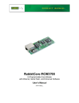
1
AN406
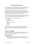
Will That Be Serial or Ethernet?
Introduction
Ethernet networks and the Internet are rapidly becoming the preferred means for connecting remote devices,
and Web browsers provide an easy access to display data and otherwise interface with the remote devices.
Regardless of whether you’re collecting data automatically or are looking at a remote device of one kind or
another, you’re going to eventually have to connect your device to a PC or other terminal. In many cases
that connection will likely be through a network of some kind. A serial RS-232 or RS-485 network may
suffice for short distances, but you’ll have to use an Ethernet/Internet network for long-distance or worldwide connectivity. Ethernet/Internet connections will also help you view and control multiple devices
when all you have is one PC or terminal with a limited number of COM ports, or maybe just a notebook
with one USB port.
Then, too, the device sending all the data might just have a single RS-232 port to save on costs, and you
will have yet another reason to convert the signal protocols. Rabbit Semiconductor’s Multi-Port Serial-toEthernet Application Kit provides you with the proven hardware and software you need to convert
between serial and Ethernet protocols or vice-versa.
The software in the Multi-Port Serial-to-Ethernet Application Kit is pretty straightforward. It initializes the
RCM3700, sets up the TCP/IP protocol stack and serial ports, and waits for a network connection from an
external host (PC) via Telnet. Once the network connection is made, the software simply moves bytes
between a serial port’s Tx and Rx and the network connection’s socket.
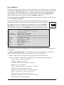
The Multi-Port Serial-to-Ethernet Application Kit Getting Started instructions included with the Application Kit show how to set up and program the RCM3700.
What Else You Will Need
Besides what is supplied with the Application Kit, you will need a PC with an available COM or USB port
to program the RCM3700 in the Application Kit. If your PC only has a USB port, you will also need an
RS-232/USB converter (Part No. 540-0070).
To run the S2E_DVM.C sample program, which uses a digital voltmeter to illustrate the use of the serial-toEthernet serial handler, you will need a digital voltmeter with a serial port such as the Radio Shack 22-812
digital voltmeter and a DB9 male to DB9 male null modem cable.
022-0099 Rev. D
1
Configuration Information
Network/IP Address Configuration
Any device placed on an Ethernet-based Internet Protocol (IP) network must have its own IP address. IP
addresses are 32-bit numbers that uniquely identify a device. Besides the IP address, we also need a netmask, which is a 32-bit number that tells the TCP/IP stack what part of the IP address identifies the local
network the device lives on as well as which host it is connected to.
The sample programs supplied with this Multi-Port Serial-to-Ethernet Application Kit already configure
the RCM3700 with a default TCPCONFIG 6 macro, which allows specific IP address, netmask,
gateway, and other network parameters to be set at runtime. This sample code shows these network
configurations, which are used by the parameters in the s2e_setnetparams() function call
#define TCPCONFIG
6
#define TCPPORT 23 // 23, 1230, …, 1233 used in the sample programs,
// 23 is the default Telnet TCP port
#define BAUDRATE 115200L // L identifies baud rate as a long variable
#define DEFAULT_IP_ADDRESS "10.10.6.100"
#define DEFAULT_GATEWAY "10.10.6.1"
#define DEFAULT_NETMASK "255.255.255.0"
#define DEFAULT_KEEPALIVE 1
// 0 = KeepAlive Off, 1 = On.
#define DEFAULT_ALIVETIME 120 // Delay Between KeepAlive pings.
#define DEFAULT_DHCP_STATE 0 // 0 = DHCP Off, 1 = On.
#define DEFAULT_USE_NAGLE 1
// 1 = Use Nagle, 0 = Do not use Nagle
Change the network settings to configure the RCM3700 with your own Ethernet settings only if that is
necessary to run the sample programs.
There are some other “standard” configurations for TCPCONFIG that let you select different features such
as DHCP. Their values are documented at the top of the TCP_CONFIG.LIB library in the LIB\TCPIP
directory. More information is available in the Dynamic C TCP/IP User’s Manual.
Serial Port Configuration
In addition to configuring the network connections, you can also configure the serial ports. Four serial
ports from the RCM3700 are used by the sample programs with this Application Kit.
Serial Port
Default Use
Alternate Use
Sample Programs
Serial Port A
Programming port
3-wire RS-232
S2E_RABBITWEB.C
Serial Port C
3-wire RS-232
RTS/CTS
S2E_SAMPLE.C
S2E_BASIC_5WIRE.C
Serial Port D
3-wire RS-232
5-wire RS-232
S2E_BASIC.C
S2E_SAMPLE.C
S2E_BASIC_5WIRE.C
S2E_TEMP_SAMPLE.C
S2E_ZCONSOLE.C
S2E_RABBITWEB.C
Serial Port E
RS-485
3-wire RS-232
S2E_SAMPLE.C
S2E_RABBITWEB.C
022-0099 Rev. D
2
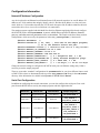
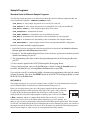
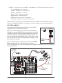
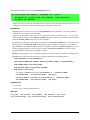
Serial Port E on the RCM3700 may be configured in hardware as either an
RS-232 or an RS-485 serial port when the RCM3700 is used with the
RCM3700 Prototyping Board. The hardware configuration details for doing
this via header JP2 on the RCM3700 Prototyping Board are shown in the
RCM3700 User’s Manual, which is available on the Dynamic C CD-ROM.
Prototyping Board
JP2
RS-232
RS-485
When Serial Port E is configured as an RS-232 serial port, its signals are
available on header J2, the “RS-232 header” on the RCM3700 Prototyping
Board. When Serial Port E is configured as an RS-485 serial port, its signals are available on header J1, the
“RS-485 connector” on the RCM3700 Prototyping Board. Serial Ports C and D are also available on
header J2, the “RS-232 header” on the RCM3700 Prototyping Board. Serial Ports C and D are RS-232
only, and must be configured in software for RS-232.
Configure Serial Ports in Software
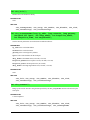
One of the first steps is to #use the serial-to-Ethernet library.
#use "SER2ETH.LIB"
Now define the serial port use via configuration macros—X here represents Serial Port A to Serial Port F.
#define S2E_USEPORT_X // Enable Serial Port X, X = A to F
#define S2E_SERX_BUFSIZE N // Serial Port X buffer size, default 255
#define S2E_SERX_USE_HANDSHAKING // Serial Port X flow control if used
These are typical settings for an RS-232 serial port.
• 8 data bits
• 1 stop bit
• No parity
• No flow control (one serial port required) or
Flow control on (two serial ports required)
• 115200 baud
Use the s2e_setup() function call from the Dynamic C SER2ETH.LIB library to set up each serial port.
s2e_setup(S2E_SERPORT_X, LOCALTCP, REMOTETCP, REMOTEIP, BAUDRATE,
S2E_DATABITS_8 | S2E_PARITY_NONE | S2E_THREE_WIRE |
S2E_ACTIVE_LISTEN | S2E_RS232);
where
S2E_SERPORT_X is the serial port being set up (X = A to F)
LOCALTCP is the TCP address of the local port—set 23 as a default Telnet address; 1230, …, 1233 are also used
in the sample programs
REMOTETCP is the TCP address of the remote port—use 0 to listen to all remote ports
REMOTEIP is the IP address of the remote port—use 0 to listen to all remote ports; always add L to the number to
indicate to Dynamic C that this is a long type of variable
BAUDRATE is the baud rate to use as declared earlier in the #define BAUDRATE line
the final parameter, the serial port parameter, is configured via a logical combination of the five macros (replace
S2E_RS232 with S2E_RS485 if you are configuring Serial Port E for RS-485)
022-0099 Rev. D
3
Call s2e_set485() if you are using Serial Port E for RS-485.
int s2e_set485(S2E_SERPORT_E, ser485Tx, ser485Rx);
When using RS-485, you will have to include code to enable and disable the RS-485 transmitter with
ser485Tx and ser485Rx as shown in the S2E_SAMPLE.C sample program.
Now use the s2e_setnetparams() function call to set up the network parameters.
s2e_setnetparams(resolve(DEFAULT_IP_ADDRESS),
resolve(DEFAULT_NETMASK), resolve(DEFAULT_GATEWAY),
DEFAULT_DHCP_STATE, DEFAULT_KEEPALIVE, DEFAULT_ALIVETIME,
DEFAULT_USE_NAGLE);
Remember to call s2e_init() to initialize the SER2ETH.LIB library.
s2e_init();
Although ASCII data encoding is the most common protocol, some serial devices use binary data or different character encoding. This means the data that are sent over the serial port might not be readily readable
via the Telnet or Hyperterminal utilities on your PC. However, the serial data will still be handled just fine
by the RCM3700 as long as a compatible device is available at the other end to receive and display the
data.
PC Configuration
This section shows how to configure your PC or notebook to run the sample programs. If the PC or notebook used with the RCM3700 is connected to a network, disconnect it from the network. Check with your
administrator if you are unable to change the settings as described here since you may need administrator
privileges. The screen shots shown here are from Windows 2000, and the interface is similar for other
versions of Windows.
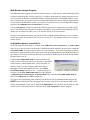
1. Go to the control panel (Start > Settings > Control Panel) and start Network Connections.
022-0099 Rev. D
4
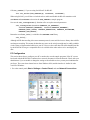
2. Select the network interface card used for the Ethernet
interface you intend to use (e.g., TCP/IP Xircom
Credit Card Network Adapter) and click on the
“Properties” button. Depending on which version of
Windows your PC is running, you may have to select
the “Local Area Connection” first, and then click on the
“Properties” button to bring up the Ethernet interface
dialog. Then “Configure” your interface card for a
“10Base-T Half-Duplex” or an “Auto-Negotiation”
connection on the “Advanced” tab.
NOTE: Your network interface card will likely
have a different name.
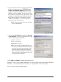
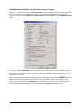
3. Now select the IP Address tab, and check Specify
an IP Address, or select TCP/IP and click on “Properties” to fill in the following fields:
IP Address : 10.10.6.101
Netmask : 255.255.255.0
Default gateway : 10.10.6.1
TIP: If you are using a PC that is already on a
network, you will disconnect the PC from that
network to run these sample programs. Write
down the existing settings before changing
them to facilitate restoring them when you are
finished with the sample programs and reconnect your PC to the network.
4. Click <OK> or <Close> to exit the various dialog boxes.
Once the PC is set up, we're ready to communicate. You can use Telnet, which comes with most Windows
installations, to view the Ethernet port, and you can use Hyperterminal to view the serial port.
Now we’re ready to run the sample programs.
022-0099 Rev. D
5
Sample Programs
Standard Serial-to-Ethernet Sample Programs
The following sample programs are available for the Multi-Port Serial-to-Ethernet Application Kit, and
can be found in the Dynamic C SAMPLES\S2EMULTI folder.
• S2E_BASIC.C—basic sample program involves one RS-232 serial port
• S2E_SAMPLE.C—basic sample program involves multiple RS-232 serial ports and RS-485
• S2E_BASIC_5WIRE.C—basic sample program shows flow control
• S2E_ZCONSOLE.C—demonstrates Zconsole
• S2E_TEMP_SAMPLE.C—demonstrates use of serial data from sensor
• S2E_HEX.C—demonstrates the functionality of the serial handler for converting data
• S2E_DVM.C—demonstrates the functionality of the serial handler with a digital voltmeter
• S2E_RABBITWEB.C—sample program with ZConsole and optional RabbitWeb configuration
In order to run these and other sample programs,
1. Your RCM3700 must be plugged in to the Prototyping Board as described in the Multi-Port Serial-toEthernet Application Kit Getting Started instructions.
2. Dynamic C and the supplementary Multi-Port Serial-to-Ethernet Application Kit software must be
installed and running on your PC.
3. The programming cable must connect the programming header on the Prototyping Board to
your PC.
4. Power must be applied to the RCM3700 through the Prototyping Board.
To run a sample program, open it with the File menu, compile it using the Compile menu (or
press F5), and then run it by selecting Run in the Run menu (or press F9).
If you only have one PC or notebook available, disconnect the programming cable once the sample
program is running. Then press the RESET button on the RCM3700 Prototyping Board to restart
the RCM3700 in the Run mode.
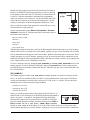
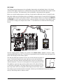
S2E_BASIC.C
This sample program gives a very basic example of three-wire RS-232 serial communication using the
serial-to-Ethernet library with Serial Port D and the standard Telnet port (23).
GND
TxD
RxD
TxE
GND
GND
RxC
TxC
RxE
Before you run this program, place one of the jumpers supplied with the spare parts in
the Application Kit between the Serial Port D Rx and Tx lines (pins 3 and 5) on header
J2 on the RCM3700 Prototyping Board. (Be careful not to confuse header J2 with
J2
nearby header JP2.) Once this sample program is running, start a Telnet session (Start
> Run > telnet 10.10.6.100) with the default Telnet socket (23). Once the
Telnet client is active (click on the Telnet window appearing on your PC desktop), anything you type on your keyboard will be echoed back by the Rabbit and will appear in the Telnet window.
To convince yourself that the RCM3700 is indeed doing the serial-to-Ethernet conversion, you can remove
the jumper between the Serial Port D Rx and Tx lines on header J2 on the RCM3700 Prototyping Board,
and you will no longer see what you type on your keyboard in the Telnet window.
022-0099 Rev. D
6
Open a Hyperterminal session (Start > Accessories > Communications). Select the PC COM port the cable is connected to and set
the default serial parameters:
Colored
edge
J2
GND
TxD
RxD
TxE
GND
Instead of using a jumper across the Serial Port D Rx and Tx lines on
header J2 on the RCM3700 Prototyping Board, you may use the long
10-pin header to DB9 cable (Part No. 540-0085) to connect header J2
to your PC COM port (remember to disconnect the programming
cable if you only have one COM port). Line up the colored edge of the
cable with pin 1 on header J2 as shown in the diagram (pin 1 is indicated by a small square on the Prototyping Board silkscreen). Note
that two of the lines in the cable opposite the colored side are not connected within the 10-pin connector.
Bits per second: 115200
Data bits: 8
Parity: None
Stop bits: 1
Flow control: None
With the Hyperterminal client active (click on the Hyperterminal window appearing on your PC desktop)
and the Telnet session you started before still running, anything you type on your keyboard will be echoed
back by the Rabbit and will appear in the Telnet window. With the Telnet client active (click on the Telnet
window appearing on your PC desktop), anything you type on your keyboard will be echoed back by the
Rabbit and will appear in the Hyperterminal window. Note that you will not see what you are typing in the
active window unless you have enabled the local echo.
To select a different serial port, change the S2E_USEPORT_D, and S2E_SERD_BUFSIZE macros in the
sample program. To select a different TCP/IP port, change the TCPPORT macro in the sample program.
Note that the long 10-pin header to DB9 cable (Part No. 540-0085) only provides a serial connection to the
PC for Serial Port D.
S2E_SAMPLE.C
This sample program is similar to the S2E_BASIC.C sample program, except three serial ports (Serial
Ports C, D, and E) are enabled for three-wire RS-232 serial communication, with a unique TCP/IP port
(socket) corresponding to each of the three serial ports. TCP/IP “ports” or “sockets” are used whenever
multiple devices are associated with a single IP address.
Serial Port C: port 1231
Serial Port D: port 1232
Serial Port E: port 1233
GND
TxD
RxD
TxE
GND
GND
RxC
TxC
RxE
Before you run this program, place jumpers between the Serial Port C, D,
and E Rx and Tx lines on header J2 on the RCM3700 Prototyping Board as
shown. Also, pins 1–3 and pins 2–4 on header JP2 on the Prototyping
J2
JP2
Board must be jumpered to set up Serial Port E as an RS-232 serial port.
Once this sample program is running, start three Telnet sessions (Start >
Run > telnet 10.10.6.100 1231)…(Start > Run > telnet
10.10.6.100 1233) to the IP address 10.10.6.100. With a Telnet client active (click on one of the
Telnet windows appearing on your PC desktop), anything you type on your keyboard will be echoed back
022-0099 Rev. D
7
by the Rabbit and will appear in that Telnet window.To convince yourself that the RCM3700 is indeed
doing the serial-to-Ethernet conversion, you can remove the jumper for the Rx and Tx lines on header J2
for the serial port you are using, and you will no longer see what you type on your keyboard in the Telnet
window. You may also try connecting the Tx line from one serial port to the Rx line of another serial port.
Instead of using jumpers across the three serial port Rx and Tx lines on header J2 on the RCM3700 Prototyping Board, you may use the long 10-pin header to DB9 cable (Part No. 540-0085). Because the PC
COM port only has one set of Tx and Rx lines, you can only view Serial Port D when you connect the
cable directly from header J2 to your PC COM port. Line up the colored edge of the cable with pin 1 on
header J2 as shown in the diagram (pin 1 is indicated by a small square on the Prototyping Board silkscreen). Note that two of the lines in the cable opposite the colored side are not connected within the
10-pin connector.
Serial Port E
J2
J2
GND
TxD
RxD
TxE
GND
GND
TxD
RxD
TxE
GND
J2
GND
RxC
TxC
RxE
Serial Port D
GND
TxD
RxD
TxE
GND
Serial Port C
GND
RxC
TxC
RxE
Colored
edge
Open a Hyperterminal session (Start > Accessories > Communications). Select the COM port the
cable is connected to and set the default serial parameters:
Bits per second: 115200
Data bits: 8
Parity: None
Stop bits: 1
Flow control: None
With the Hyperterminal client active (click on the Hyperterminal window appearing on your PC desktop)
and the Telnet session to port 1232 still running, anything you type on your keyboard will be echoed back
by the Rabbit and will appear in the Telnet window. With the Telnet window active (click on the Telnet
window appearing on your PC desktop), anything you type on your keyboard will be echoed back by the
Rabbit and will appear in the Hyperterminal window. Note that you will not see what you are typing in the
active window unless you have enabled the local echo.
You can also try out Serial Port E as an RS-485 serial port by jumpering pins
3–5 and pins 4–6 on header JP2 on the Prototyping Board before you recompile and run the sample program with the programming cable attached. You
will also need to uncomment the #define USE_RS485_ON_SER_E
line in the sample program by removing the // characters. Once you’re
022-0099 Rev. D
RS-485
GND
RS-485+
You can repeat this activity via the long cable by connecting Serial Port C or Serial Port E from header J2
to the cable 10-pin connector with hookup wire to the cable 10-pin connector positions shown in the above
diagram.
J1
JP2
8
running the revised sample program, you can proceed as before. You will not see any characters typed in
the Telnet window echoed back. The RS-485 signals will be on header J1 of the RCM3700 Prototyping
Board, and can be observed with an oscilloscope. Alternatively, you may connect an RS-485 device of
your own to header J1 to get a visual indication that the RS-485 to Ethernet conversion is taking place.
S2E_BASIC_5WIRE.C
This sample program provides an example of five-wire RS-232 serial communication with flow control.
Serial Port D is used as a regular RS-232 serial port, and the two flow control signals (RTS and CTS) are
derived from the Serial Port C signals, which are used as a digital input and output.
GND
TxD
RxD
TxE
GND
GND
RxC
TxC
RxE
Before you run this program, place one of the jumpers supplied with the spare parts in
the Application Kit between the Serial Port D Rx and Tx lines on header J2 on the
RCM3700 Prototyping Board. Then place a second jumper between the Serial Port C
J2
Rx and Tx lines on header J2. Once this sample program is running, start a Telnet
session (Start > Run > telnet 10.10.6.100) to the default Telnet socket (23).
With the Telnet client active (click on the Telnet window appearing on your PC desktop), anything you type on your keyboard will be echoed back by the Rabbit and will appear in the Telnet
window. To convince yourself that the RCM3700 is indeed doing the serial-to-Ethernet conversion, you
can remove the jumper between the Serial Port D Rx and Tx lines on header J2 on the RCM3700 Prototyping Board, and you will no longer see what you type on your keyboard in the Telnet window. To check the
flow control, leave the jumper in place between the Serial Port D Rx and Tx lines on header J2, and
remove the jumper between the Serial Port C Rx and Tx lines on header J2. No communication will occur
when this Serial Port C jumper is removed.
Open a Hyperterminal session (Start > Accessories > Communications). Select the COM port the cable is connected to and set the
default serial parameters:
Colored
edge
J2
GND
TxD
RxD
TxE
GND
Instead of using a jumper across the Serial Port D Rx and Tx lines on
header J2 on the RCM3700 Prototyping Board, you may use the long
10-pin header to DB9 cable to connect header J2 to your PC COM
port. Line up the colored edge of the cable with pin 1 on header J2 as
shown in the diagram (pin 1 is indicated by a small square on the
Prototyping Board silkscreen). Note that two of the lines in the cable
opposite the colored side are not connected to the 10-pin connector.
Bits per second: 115200
Data bits: 8
Parity: None
Stop bits: 1
Flow control: Hardware
With the Hyperterminal client active (click on the Hyperterminal window appearing on your PC desktop)
and the Telnet session you started before still running, anything you type on your keyboard will be echoed
back by the Rabbit and will appear in the Telnet window. With the Telnet window active (click on the
Telnet window appearing on your PC desktop), anything you type on your keyboard will be echoed back
by the Rabbit and will appear in the Hyperterminal window. Note that you will not see what you are typing
in the active window unless you have enabled the local echo.
022-0099 Rev. D
9
S2E_ZCONSOLE.C
This sample program demonstrates how to perform serial and network configuration using a console based
on the Dynamic C ZCONSOLE.LIB library. The console functionality can be embedded in an application
to allow network and serial configurations to be changed without having to rewrite and recompile the
whole application. The console functionality is wrapped by the Dynamic C S2E_ZCONSOLE.LIB
library, which interfaces directly with the Dynamic C SER2ETH.LIB library.
J2
GND
TxD
RxD
TxE
GND
Before you run this program, place one of the jumpers supplied with the spare parts in the
Application Kit between the Serial Port D Rx and Tx lines on header J2 on the RCM3700
Prototyping Board. Once this sample program is running, start a Telnet session (Start >
Run > telnet 10.10.6.100) to the default TCP socket (23). The console will be
displayed in the Telnet window. Type help<return> to display the available commands.
GND
RxC
TxC
RxE
More information about the ZCONSOLE.LIB library and settings and structures can be found in Chapter
17 of the TCP/IP User’s Manual.
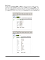
Available Commands: (type "help <command>" for more info)
ECHO
HELP
LOGIN NAME
LOGIN PASSWORD
SETx
SETNET
SHOW SERx
SHOW NET
STORE
RECALL
RESTART
EXIT
LOGOUT
Turn on or off echoing of characters.
This help Screen.
Change or set login name.
Change or set password.
Set Serial port attributes. Replace x with serial port.
Set network settings.
Show serial port settings. Replace x with serial port.
Show network settings.
Store settings.
Undo unstored changes.
Restart device.
Exit console.
Logout.
The x serial ports in the SETx and SHOW SERx commands correspond to x = 0 = Serial Port D and x = 1
= Serial Port E
Type help <command><return> for more information about the ECHO, SETNET, and SETx commands. The type of additional information is listed here for the various commands:
• ECHO—“echo off” will stop the characters being input from being echoed back.
• SETx—is used in the context “setx <parameter>”. The following parameters can be set.
status on|off —enable or disable port
baudrate <number>—baud rate
sermode rs232|rs485—select RS-232 or RS-485
databits 8|7—serial data bits
parity even|odd|none|2—serial parity (2 = 2 stop bits)
flow on|off—enable hardware flow control
ipmode listen|open—listen or actively open connection
rport <tcp port>—remote port (0–65536) to use
lport <tcp port>—local port (0–65536) to use
raddress <ip address>—remote IP address to connect to
flush on|off—enables socket flushing
022-0099 Rev. D
10
• SETNET—is used in the context “setnet <parameter>”. The following parameters can be set.
ip <ip address>—exa 10.10.6.99
netmask <netmask>—exa 255.255.255.0
gateway <gateway>—exa 10.10.6.1
dhcp on|off—enable or disable DHCP
nagle on|off—turn nagle on or off
keepalive on|off—turn on TCP keepalives
alivetime <seconds>—how often to test keepalive
When you change any settings, you must store them and restart the device before the changes will take
effect. If you changed the IP address, you will have to start a new Telnet session to the new IP address.
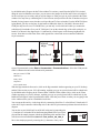
S2E_TEMP_SAMPLE.C
Before you run this sample program, use the short 10-pin header to
DB9 cable to connect the QK145 temperature sensor to Serial Port D
via header J2 on the RCM3700 Prototyping Board. Most of the time,
the RS-232 chip on the Prototyping Board can supply sufficient current to operate the QK145 temperature sensor—connect pins 1–3 and
pins 2–4 on header JP2 on the Prototyping Board to configure Serial
Port E for RS-232 operation.
GND
RxC
TxC
RxE
This sample program illustrates using a serial device, the QK145
temperature sensor, to provide the serial data.
J2
JP2
Colored
edge
Once the sample program is running, start a Telnet session (Start >
Run > telnet 10.10.6.100 1230) to the IP address
10.10.6.100 and Telnet port 1230. The serial data sent by the QK145 temperature sensor will be displayed
in the Telnet window.
Crossover
Ethernet Cable
To
PC
RXC TXC RXE
NC
D4
D2
D0
A1
A3
GND
LED6
LED4
LED2
D6
D7
D5
D3
A0
A2
D1
D0
D2
D4
D6
GND
D1
D3
D5
D7
GND
GND
A1
LED6
A1
LED4
LCD1JC
A3
LED2
GND
LCD1JB
A2
LDE0
GND
+V
/RESET
/CS
CX5
JP7
C8
Optional +5 V and GND
connections
Y3
CX7
C57
R35 R36
CX8
C35
UX2
R43
C32
C33
R41 R42
CX11
AGND
01
03
04
R39 R40
02
C30
C31
R44
THERM_IN R37
AGND
CONVERT
R31 R32 R33 R34
C29
AIN
R38
06
JP8
J7
THERMISTOR
05
R30
R29
VREF
R29
R31
R28
DS1
CX9
CX10
DS3
DS2
J8
R48
DS2
U11
C22
CX6
R27
RCM36/37XX SERIES
PROTOTYPING BOARD
LED5
CX3
CX4
NC
NC
JP6
NC
NC
NC
NC
JP5
LED3
VBAT
CX2
LED1
PD4
UX1
C28
R45
R49
DS18S20 sensor
PE1
+BKLT
R33
C12
R24
R26
GND
PE5
+5V
L1
C14
C40
CX1
PC0_TXD
+5V
PG7_RXE
+3.3V
PC1/PG2
PE0
PG6
TXE
PD5
QK145
Temperature
Sensor Kit
LCD1JA
GND
C49
C10
R11 C37
2
PF7
PC3/
PG3
PC2
TXC
PE4
LED0
PF6
BT1
GND
PF5
R15
/RSTET
PF4
LED5
+5V
PF1
+V
/RES
PF0
/CS
PB0
PB7
LED3
PA6
PA7
LED1
PA5
R14
+BKLT
PA4 PA2
PA0
PA3
DCIN
U2
C18
U6
C17
U5
+3.3V
PA6
PA4
PA2
PF0
PA0
PB2
L2
Q1
1
PB2
RP1
JP4
U8
00 C34
AIN
R32
R30
J3
T1
R23
C24
C25
GND
TXE
GND
PA5
PA3
PA1
PF1
PB0
PB3
PB5
PF6
PC0_TXD
PC2_TXC
PE7
PE4
PE0
PF4
PB7
PG6_TXE
/IORD
PD5
VBAT
R28
L3
R7
PE5
PB4
U4
R34
C21
C24
L6
R15
R16
C36 Y1
C39
R13
C29
C16
D1
C53
+5V
C8
C10
C20
U5
R5
R4
L4
C54 C55
PC1/ PF7
PG2 PF5
C38
C41
DS1
U6
JP3
PC3/PG3
C17
C7
PD4
C15
R6
R22
C23
U7
C27
R25
C31
GND
C32 C30
C21
L2
R18 R19
R20
PA7
J2
JP1
C19
U1 C25 U3
C33
/RES
C35
C34
JP2
/IOWR
PG7
RXE
C20 PE1
C18
C27 C28
GND
R18
R36
TCM_SMT_SOCKET
PB3
PA1
C11
R13
C26
U8
R21
C7
R12
R24 R2
R26
C23
C58
C26
TXD
485
C9
+485
R11
J5
PB5
PB4
L1
C16
/IORD
PE7
D2
C13
GND
GND
/IOWR
C6
U4
RP2
U3
C3
C22
C19
D1
J4
C5
GND JP2
C4
R5
R16
C14
C15
C12
J1
RXD
JP1
R1
R2
R3
R4
RP1
Rx
IR1
R6
U1
J2
R9
GND
R8
R7
C2
Tx
GND
C1
R46
R47
RESET
S1
S2
S3
022-0099 Rev. D
11
Should you encounter any problem viewing the data output in the Telnet window once the sample program
is running, you will have to connect the QK145 temperature sensor to the +5 V and GND traces on the
Prototyping Board.
S2E_HEX.C
This sample program demonstrates the functionality of the serial handler using the serial-to-Ethernet library
with Serial Port D and the standard Telnet port (23). The serial handler takes a single ASCII byte from the
serial port and translates it into two hexadecimal characters and a space, which makes it easier to observe and
process certain types of data streams. The functionality of the serial handler is documented in the appendix.
GND
TxD
RxD
TxE
GND
GND
RxC
TxC
RxE
Before you run this program, place one of the jumpers supplied with the spare parts in
the Application Kit between the Serial Port D Rx and Tx lines (pins 3 and 5) on header
J2 on the RCM3700 Prototyping Board. (Be careful not to confuse header J2 with
J2
nearby header JP2.) Once this sample program is running, start a Telnet session (Start
> Run > telnet 10.10.6.100) with the default Telnet socket (23). Once the
Telnet client is active (click on the Telnet window appearing on your PC desktop), anything you type on your keyboard will have its hex equivalent echoed back by the Rabbit and will appear in
the Telnet window. To convince yourself that the RCM3700 is indeed doing the serial-to-Ethernet conversion, you can remove the jumper between the Serial Port D Rx and Tx lines on header J2 on the RCM3700
Prototyping Board, and you will no longer see the hex equivalent from your keyboard in the Telnet window.
Open a Hyperterminal session (Start > Accessories > Communications). Select the PC COM port the cable is connected to and set the
default serial parameters:
Colored
edge
J2
GND
TxD
RxD
TxE
GND
Instead of using a jumper across the Serial Port D Rx and Tx lines on header
J2 on the RCM3700 Prototyping Board, you may use the long 10-pin header
to DB9 cable (Part No. 540-0085) to connect header J2 to your PC COM
port (remember to disconnect the programming cable if you only have one
COM port). Line up the colored edge of the cable with pin 1 on header J2 as
shown in the diagram (pin 1 is indicated by a small square on the
Prototyping Board silkscreen). Note that two of the lines in the cable opposite the colored side are not connected within the 10-pin connector.
Bits per second: 57600
Data bits: 8
Parity: None
Stop bits: 1
Flow control: None
With the Hyperterminal client active (click on the Hyperterminal window appearing on your PC desktop)
and the Telnet session you started before still running, anything you type on your keyboard will have its
hex equivalent transferred by the Rabbit and will appear in the Telnet window. With the Telnet client active
(click on the Telnet window appearing on your PC desktop), anything you type on your keyboard will be
transferred by the Rabbit without a hex conversion and will appear in the Hyperterminal window. Note that
you will not see what you are typing in the active window unless you have enabled the local echo.
To select a different serial port, change the S2E_USEPORT_D, and S2E_SERD_BUFSIZE macros in the
sample program. To select a different TCP/IP port, change the TCPPORT macro in the sample program.
Note that the long 10-pin header to DB9 cable (Part No. 540-0085) only provides a serial connection to the
PC for Serial Port D.
022-0099 Rev. D
12
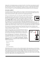
S2E_DVM.C
This sample program demonstrates the serial handler functionality with the Radio Shack 22-812 digital
voltmeter. This digital voltmeter has a at 4800 baud serial port that sends information about what is on the
screen out its serial port. The functionality of the serial handler is documented in the appendix.
Before you run this sample program, use the long 10-pin header to DB9 cable (Part No. 540-0085) and a
DB9 male to DB9 male null modem cable (not included) to connect header J2 on the RCM3700 Prototyping Board to the serial port on the digital voltmeter. Turn the digital voltmeter on, and press the SELECT
and RANGE keys at the same time to turn on the serial port interface on the meter. Use the digital voltmeter to measure a voltage (for example, between the +5 V and GND traces on the RCM3700 Prototyping
Board).
Crossover
Ethernet Cable
To
PC
DE9 Null Modem
Cable
RXC TXC RXE
NC
D4
D2
D0
A1
A3
GND
LED6
LED4
LED2
LED0
/RSTET
D6
+5V
+3.3V
D7
D5
D3
A0
A2
GND
GND
LED5
D1
A1
D0
D2
D4
D6
GND
A1
D1
D3
D5
D7
GND
NC
NC
NC
NC
NC
NC
LCD1JC
CX4
CX5
JP7
C8
U11
Y3
C57
R29
R31
C22
CX6
R27
CX7
R28
CX8
C35
R43
UX2
CX11
AGND
01
R41 R42
02
03
04
R39 R40
R35 R36
00 C34
AIN
C32
C33
C30
C31
R44
THERM_IN R37
AGND
VREF
CONVERT
R31 R32 R33 R34
C29
AIN
R38
06
JP8
J7
THERMISTOR
05
R30
R29
DS1
CX9
CX10
DS3
DS2
J8
R48
RCM36/37XX SERIES
PROTOTYPING BOARD
LCD1JB
A3
CX3
A2
R33
C12
R26
JP6
+V
VBAT
/RESET
PD4
CX2
/CS
L1
C14
JP5
+V
PE1
UX1
C28
LED3
PE5
+BKLT
C49
JP4
U8
PC0_TXD
RP1
R24
/CS
PG7_RXE
CX1
LED1
PE0
PG6
TXE
PD5
+BKLT
PC1/PG2
GND
PF6
LED6
PF5
PF7
PC3/
PG3
PC2
TXC
PE4
LCD1JA
LED4
PF4
BT1
LED2
PF1
R15
GND
+5V
LDE0
/RES
GND
PB0
LED5
PA6
PA7
PF0
DCIN
R14
LED3
PA5
PB7
U5
LED1
PA3
PA4 PA2
PA0
+5V
Q1
1
PB3
PB2
GND
R11 C37
2
DS2
U7
PB5
PB4
U2
C18
U6
C17
+3.3V
PA6
PA4
PA2
PF0
PA0
PB2
L2
R7
C10
C40
R22
R23
C24
C25
GND
TXE
GND
PA5
PA3
PA1
PF1
PB0
PB5
PF4
PF6
PE7
PE4
PE0
PC0_TXD
PC2_TXC
PG6_TXE
/IORD
R32
R30
J3
T1
L6
R15
R16
C36 Y1
C39
R13
C29
PD5
PB3
PB4
PB7
U5
R5
R4
U4
R28
VBAT
C8
C10
R6
C20
R34
C21
C24
L3
PC1/ PF7
PG2 PF5
C38
C41
L4
C16
D1
C53
C54 C55
PC3/PG3
C17
DS1
U6
JP3
PE5
C15
C7
PD4
C31
GND
C32 C30
JP2
/RES
C33
C27 C28
C21
L2
R18 R19
R20
C23
C27
R25
PA7
J2
JP1
C19
U1 C25 U3
C26
U8
/IOWR
PG7
RXE
C20 PE1
C35
C34
+5V
C18
R13
TCM_SMT_SOCKET
PE7
L1
C16
/IORD
PA1
C11
R18
R24 R2
GND
C7
R12
R36
R26
C23
C58
C26
R21
TXD
485
C9
+485
R11
J5
U4
RP2
U3
D2
C13
GND
GND
/IOWR
C6
GND JP2
C4
C3
C22
C19
D1
J4
C5
RXD
J1
R5
R16
C14
C15
C12
RP1
Rx
JP1
R1
R2
R3
R4
R6
U1
J2
R9
GND
R8
R7
C2
Tx
GND
C1
IR1
R45
R49
R46
R47
Serial
Digital Voltmeter
RESET
S1
S2
S3
Once the sample program is running, start a Telnet session (Start > Run > telnet 10.10.6.100)
with the default Telnet socket (23). An ASCII text representation of the serial data sent by the digital voltmeter will be displayed in the Telnet window.
The data from the digital voltmeter LCD are sent out the serial port in packets of
9 bytes. The first byte describes the mode and the next two bytes describe the
units; the next four bytes describe the number on the screen as it is drawn (the P
is the decimal point)—the bytes are from right to left as they appear on the LCD.
The eighth byte represents some special symbols on the LCD, and the final byte
is a checksum of the packet. The sample program converts each packet received
into an equivalent ASCII text string that is then displayed in the Telnet window.
A
F
B
G
E
P
C
D
The sample program and the manual for the digital voltmeter provide additional information about the
nine-byte data strings and the voltmeter modes.
022-0099 Rev. D
13
Web Browser Sample Program
One additional sample program is available to illustrate the use of a Web browser with the Multi-Port Serialto-Ethernet Application Kit. A binary image file is available to demonstrate the sample program for users
who do not have the Dynamic C RabbitWeb module installed; the Dynamic C RabbitWeb module is available at a reduced price to customers who have purchased this Multi-Port Serial-to-Ethernet Application Kit.
If you purchased the RabbitWeb module, you will have to install it before you run the RabbitWeb sample
program in the SAMPLES\Serial2Ethernet_2 folder.
Like the S2E_BASIC.C sample program, this sample program can be evaluated by tying the Rx and Tx
lines of Serial Ports D and E together via jumpers on header J2 of the RCM3700 Prototyping Board. The
jumpers are not required to simply view or use the Web console or the serial console.
The Web browser sample program uses both Serial Port A and the standard Telnet port (23) as a console.
Serial Ports D and E are associated with TCP ports 1230 and 1231. The standard Telnet port 23 is used as a
remote console.
No RabbitWeb Module—Install BIN File
An already compiled binary image is available in the SAMPLES\Serial2Ethernet_2\RabbitWeb
folder for users who do not have the Dynamic C RabbitWeb module installed or do not want to compile the
S2E_RABBITWEB.C sample program at this time. Close Dynamic C if you have it running on your desktop, but leave the programming cable in place between the programming header of the RCM3700 and your
PC COM port. The crossover Ethernet should be in place between the RJ-45 jack on the RCM3700 and the
Ethernet card on your PC.
Load the S2E_RABBITWEB.BIN file with the Rabbit Field
Utility, which is available as part of your Dynamic C installation
in the Dynamic C Utilities folder. Locate this folder via
Windows Explorer or My Computer, and double-click on
Rfu.exe to launch the Rabbit Field Utility. Select File >
Load Flash Image and click on the … beside the dialog box
to browse for the S2E_RABBITWEB.BIN file in the Dynamic
C SAMPLES\Serial2Ethernet_2\RabbitWeb folder. Select the S2E_RABBITWEB.BIN file,
then click on Open and press OK to load the file.
Now remove the programming cable connector from the RCM3700 programming header and press the
RESET button on the RCM3700 Prototyping Board. Launch a Web browser and enter the URL for this
sample program http://10.10.6.100/ in the Address line. You should be able to bring up a Web
console version of the serial console we looked at in the S2E_ZCONSOLE.C sample program.
022-0099 Rev. D
14
RabbitWeb Module Installed—Compile and Run Sample Program
Before you can compile and run the S2E_RABBITWEB.C sample program, you must enable the separate
I&D space compiler option to handle this program’s need for more than 24 Kbytes of root data. This
option is accessible from the Options > Project Options or the Compiler tab of the Option/Project
dialog.
Now open the S2E_RABBITWEB.C sample program, and compile and run it by pressing F9. You could
get a “target not responding message” because the console will interrupt the debugging interface, but you
may ignore that message.
Remove the programming cable from the RCM3700 programming header and press the RESET button on
the RCM3700 Prototyping Board. Launch a Web browser and enter the URL for this sample program
http://10.10.6.100/ in the Address line. You should be able to bring up a Web-based console
that is similar to the serial console we looked at in the S2E_ZCONSOLE.C sample program.
022-0099 Rev. D
15
Web Console
The Web console has Network, SER0, and SER1 tabs, which correspond to the SETNET and SETx
commands in the S2E_ZCONSOLE.C sample program, with SER0 = Serial Port D and SER1 = Serial
Port E. Once you have changed to parameters on a Web console screen, press the Submit button to save
them, or press the Recall button to recall the previous settings. New settings will not take effect until you
press the Store button (which comes up after you press the Submit button) and then the Restart button.
022-0099 Rev. D
16
Serial Console
You can also bring up the serial console on Serial Port A by connecting the DIAG connector on the programming cable to the programming header on the RCM3700; the other end of the programming cable is
still connected to the COM port on your PC. Open a Hyperterminal session (Start > Accessories >
Communications). Select the COM port the programming cable is connected to and set the default
serial parameters:
Bits per second: 57600
Data bits: 8
Parity: None
Stop bits: 1
Flow control: None
With the Hyperterminal client active (click on the Hyperterminal window appearing on your PC desktop),
you should see the serial console that we looked at in the S2E_ZCONSOLE.C sample program. (You may
have to press <return> or type help<return> to start the serial console.)
Comparing Consoles
What you save in one console is reflected in what is displayed in the other console. For example, try
changing the network IP address from 10.10.6.100 to 10.10.6.103 in the Network screen of the Web
console. After you press the Submit button, the Store button (which comes up after you press the
Submit button), and the Restart button, the Web browser will display Restarting…. You will to enter
the new URL http://10.10.6.103/ in the Web browser’s Address line to view the changed
network settings, or you can type show net<return> to view them using the serial console.
Now let’s change things back using the serial console. Type setnet ip 10.10.6.100<return> in the
serial console (followed by store<return> and restart<return>) and refresh your Web browser with
the URL http://10.10.6.100/ in the Web browser’s Address line.
In summary, we have shown three ways that network and serial parameters can be viewed and configured.
• Via a Web browser as shown in the S2E_RABBITWEB.C sample program
• Via Hyperterminal through a serial interface as shown in the S2E_RABBITWEB.C sample program
• Via Telnet through an Ethernet interface as shown in the S2E_ZCONSOLE.C sample program
022-0099 Rev. D
17
Appendix — Software Reference
Sample Program
Let’s examine some of the code in the S2E_BASIC.C sample program.
First, the program settings used at startup are defined. These settings are using by the parameters in the
s2e_setup() and the s2e_setnetparams() function calls.
#define
#define
#define
#define
#define
#define
#define
#define
#define
#define
TCPPORT
23
// Default telnet service port
BAUDRATE 115200
DEFAULT_IP_ADDRESS "10.10.6.100" // IP Address.
DEFAULT_GATEWAY "10.10.6.1"
// Gateway.
DEFAULT_NETMASK "255.255.255.0" // Netmask.
DEFAULT_KEEPALIVE 1
// 0 = KeepAlive Off, 1 = On.
DEFAULT_ALIVETIME 120
// Delay Between KeepAlive pings.
DEFAULT_DHCP_STATE 0
// 0 = Dhcp Off, 1 = On.
DEFAULT_USE_NAGLE 1
// 1 = Use Nagle, 0 = No use Nagle
SERIALPORT S2E_SERPORT_D // Select Serial Port D
Next, the SER2ETH.LIB library settings are defined.
#define S2E_USEPORT_D
// Enable Serial Port D
#define S2E_SERD_BUFSIZE 511 // Serial Port D buffer size
#define S2E_ACKNOWLEDGE
// Acknowledge an established connection.
// #define S2E_DEBUG
// For single-stepping through library
// #define S2E_VERBOSE // For displaying handler status
Now select a setting for the TCPCONFIG.LIB library. TCPCONFIG 6 allows the network interface to be
set up manually using the macros in lines 27–34 above.
#define TCPCONFIG 6
Remember to #use the SER2ETH.LIB library.
#use
"ser2eth.lib"
The brdInit() function call initializes the Rabbit microprocessor.
brdInit();
// Initialize Rabbit
The sock_init() function call initializes the Dynamic C DCRTCP.LIB library used for TCP/IP.
sock_init();
// Initialize dcrtcp library
022-0099 Rev. D
18
Set bit 5 low on Parallel Port E of the Rabbit 3000 microprocessor to enable the RS-232 chip on the RCM700 Prototyping Board.
#if (_BOARD_TYPE_ >= RCM3600A && _BOARD_TYPE_ <=
BitWrPortI(PEDR,&PEDRShadow,0,5);
#endif
0x1FFF)
Initialize the SER2ETH.LIB library.
s2e_init();
Set up each serial port.
s2e_setup(SERIALPORT, TCPPORT, 0, 0L, BAUDRATE,
S2E_DATABITS_8 | S2E_PARITY_NONE | S2E_THREE_WIRE |
S2E_ACTIVE_LISTEN | S2E_RS232);
Set up the global network parameters.
s2e_setnetparams (resolve(DEFAULT_IP_ADDRESS),
resolve(DEFAULT_NETMASK),
resolve(DEFAULT_GATEWAY),
DEFAULT_DHCP_STATE,
DEFAULT_KEEPALIVE,
DEFAULT_ALIVETIME,
DEFAULT_USE_NAGLE);
The TCP interface is brought up using the parameters stored in flash memory.
s2e_connect();
The sample program now loops until the interface comes up and then loops continuously to perform the
serial-to-Ethernet conversions.
022-0099 Rev. D
19
Serial Handler
A callback is provided with the serial-to-Ethernet software to allow you to interpret data before sending it
out the TCP connection. The Multi-Port Serial-to-Ethernet Application Kit has two sample programs,
S2E_HEX.C and S2E_DVM.C, to illustrate this functionality. The function prototype of the serial handler
in the S2E_HEX.C sample program looks like this.
int serhandler_hex(S2EControl* ctrl)
{
...
}
The serhandler_hex() function takes a pointer to an S2EControl structure, which provides the
user context and access to the serial-to-Ethernet connection. After a TCP connection has been established,
the userstate variable gets initialized to zero. This value is intended to be used by the handler to track
any state information. There is also a void* member userdata, which can be used for an extended data
structure if more state information is needed. The userdata member is initialized to zero at the beginning of the program by the s2e_init() function call, and unlike userdata does not get reinitialized
on each new connection.
The S2EControl structure provides members to access the TCP and serial sides of the connection. The
sock member can be used with the TCP functions as outlined in the TCP/IP User’s Manual. The structure also has function pointers to the underlying serial routines as outlined in the following table. Each of
the function pointers maps directly to functions in the Dynamic C RS232.LIB library.
Member
Maps to
open
serXopen
close
serXclose
rdFlush
serXrdFlush
wrFlush
serXwrFlush
rdUsed
serXrdUsed
read
serXread
peek
serXpeek
write
serXwrite
databits
serXdatabits
parity
serXparity
flowcontrolOn
serXflowcontrolOn
flowcontrolOff
serXflowcontrolOff
TxOn
serXTxOn
RxOn
serXRxOn
wrUsed
serXwrUsed
wrFree
serXwrFree
022-0099 Rev. D
20
In addition to the function pointers, there are several data members that can be used by the handler. The
serbuf member is a buffer that can be used to store data either temporarily or across handler calls. The
bufsize member gives the size of the serbuf member in bytes. The serlen member is the number
of bytes available on the serial port.
Let’s look at the S2E_HEX.C sample program. The serialhandler_hex() function takes a single byte from the serial port and translates it into two hexadecimal characters and a space. This handler
both serves as an example of a serial handler and can be generally useful for looking at the characters from
a serial port.
The serialhandler_hex() function gets called any time there is a valid TCP connection and there is
serial data to process. We do not use the userstate in this handler because any bytes that we choose to
remove from the serial ports are processed completely. If there is not room in the TCP transfer buffer, we
do not remove characters from the serial port. The return value of the serialhandler_hex() function is the number of bytes to send out the serial port. The sock_tbleft() function can be used to
insure the write fit in the buffer.
The S2E_DVM.C sample program provides an example for using the userstate member.
The serial-to-Ethernet control structure has certain states and data. The sample program shows how the
control structure is used to set up the serial handler.
int serhandler_hex(S2EControl* ctrl)
The line below ensures that only as many bytes as can be transmitted are read. Since one byte is converted
into a three-character hex representation, the number of original bytes is multiplied by three.
if((ctrl->serlen*3)>sock_tbleft(&ctrl->sock))
ctrl->serlen=sock_tbleft(&ctrl->sock)/3;
The same action needs to happen on the buffer so that the buffer and the memory do not overflow. If there
is not buffer space to write the full amount, characters may be dropped.
if((ctrl->serlen*3)>ctrl->bufsize)
ctrl->serlen=ctrl->bufsize/3;
memset(ctrl->serbuf,0,ctrl->bufsize);
Next, the bytes are read from the serial port and are replaced.
ctrl->read(ctrl->serbuf,ctrl->serlen,5L);
for(x=ctrl->serlen-1;x>=0;x--) {
The least significant nibble is done first because we do not want to overwrite the number before we calculate the most significant nibble. The hex conversion is done nibble by nibble. When the least significant
nibble is done, the actual byte is replaced, and the space is written.
022-0099 Rev. D
21
The serial handler should return the number of bytes to write to the TCP port.
return ctrl->serlen*=3;
We’re now ready to look at the main part of the program where s2e_init() initializes the
userdata member.
s2e_init();
The serial handler control structure can now be installed for the given serial port with the
s2e_setserhandler() function call.
s2e_setserhandler(SERIALPORT,serhandler_hex);
The s2e_tick() function calls the serial handler when serial data are available.
s2e_tick();
022-0099 Rev. D
22
Function Reference Guide
The Dynamic C SerialtoEthernet_2.0\SER2ETH.LIB library provides the function calls used
with the Multi-Port Serial-to-Ethernet Application Kit. Console support is provided in the
SerialtoEthernet_2.0\S2E_ZCONSOLE.LIB library.
The following macros are used throughout with the SER2ETH.LIB library and the serial-to-Ethernet
sample programs.
• S2E_USEPORT_X (where X = A to F, corresponding to Serial Port A to Serial Port F) must be defined
prior to the #use SER2ETH.LIB statement to use the specified serial port. For example, use the
following line for Serial Port D.
#define S2E_USEPORT_D // Enable Serial Port D
• S2E_SERX_BUFSIZE (where X = A to F, corresponding to Serial Port A to Serial Port F) sets the
size of the serial-to-Ethernet transmit and receive buffers. The default is 255. For example, use the
following line to set a buffer size of 511 for Serial Port D.
#define S2E_SERD_BUFSIZE 511 // Serial Port D buffer size
• S2E_SERX_USE_HANDSHAKING (where X = A to F, corresponding to Serial Port A to Serial Port F)
must be defined prior to the #use SER2ETH.LIB statement when using RTS/CTS Handshaking
for the specified serial port. For example, use the following line when using Serial Port D for Rx and
Tx with RTS/CTS on Serial Port C.
#define S2E_SERD_USE_HANDSHAKING // Enable Serial Port D flow control
• S2E_ACKNOWLEDGE will send an acknowledgement message to both the serial port and the TCP/IP
connection, when a socket connection is made.
• S2E_ACK_MESSAGE is the message string to send when S2E_ACKNOWLEDGE is used.
#define S2E_ACK_MESSAGE "This is a sample message."
• S2E_SERPORT_X (where X = A to F, corresponding to Serial Port A to Serial Port F) is used in the
s2e_setup, s2e_enable() and s2e_disable() function calls.
• S2E_ACTIVE_OPEN configures a serial port in s2e_setup() as a TCP client that connects to a
TCP server.
• S2E_ACTIVE_LISTEN configures a serial port in s2e_setup() as a TCP server that will listen
for a connection from a TCP client.
• S2E_STARTING_STORAGE_ADDR is the starting location in the user block for storage and retrieval
of all serial port TCP/IP settings. The default starting location is 0.
Two debugging macros are handy when debugging applications written with the SER2ETH.LIB library.
• S2E_DEBUG allows you to single-stepping through the library.
• S2E_VERBOSE displays status information for the s2e_tick() function call.
022-0099 Rev. D
23
The following function calls are in the SER2ETH.LIB library.
int s2e_setup(int serport, unsigned int l_port,
unsigned int ip_port,long rem_address, long baudrate,
unsigned int params);
Assigns a serial port to an IP port. This function must be the first serial-to-Ethernet function used. After the setup
is completed, this function will also enable the serial port for Ethernet connectivity.
PARAMETERS
serport is the serial port to set up—use the S2E_SERPORT_X macro (where X = A to F, corresponding to
Serial Port A to Serial Port F) for this parameter
l_port is the TCP address of the local port—the default is 23 for Telnet connections; 1230, …, 1233 are also
used in the sample programs. In the ACTIVE_LISTEN mode the port listens for a connection at the TCP address,
and in the ACTIVE_OPEN mode the port is used to send data.
ip_port is the TCP address of the remote port to listen to in the ACTIVE_LISTEN mode—use 0 to listen to all
the remote ports; in the ACTIVE_OPEN mode ip_port is the TCP address of the remote port to connect to
rem_address is the IP address of the remote port—an address is required if the ACTIVE_OPEN macro was set
with the ip_port parameter; a value of 0 can be passed if the ACTIVE_LISTEN macro was set with the
ip_port parameter and the remote IP address is required
baudrate is the baud rate to use—add L to the baud rate to indicate to Dynamic C that this is a long variable
params are the serial port parameters based on a logical combination of the following macros:
S2E_DATABITS_8 or S2E_DATABITS_7
S2E_PARITY_NONE, S2E_PARITY_ODD, S2E_PARITY_EVEN, or S2E_STOPBITS_2
S2E_THREE_WIRE or S2E_FIVE_WIRE
S2E_ACTIVE_OPEN or S2E_ACTIVE_LISTEN
S2E_RS232 or S2E_RS485
For example, a params string could be S2E_DATABITS_8 | S2EPARITY_NONE |
S2E_THREE_WIRE | S2E_ACTIVE_LISTEN | S2E_RS232
S2E_DEF_PARAM sets up params using S2E_DATABITS_8 | S2EPARITY_NONE |
S2E_THREE_WIRE | S2E_ACTIVE_LISTEN | S2E_RS232
RETURN VALUE
1 if successful.
-1 if there was a COM port initialization error.
SEE ALSO
s2e_init, s2e_set485, s2e_enable, s2e_disable, s2e_tick,
s2e_savesettings, s2e_recallsettings, s2e_setnetparams
022-0099 Rev. D
24
int s2e_init();
Initialize the serial-to-Ethernet library.
RETURN VALUE
None.
SEE ALSO
s2e_setnetparams, s2e_setup, s2e_enable, s2e_disable, s2e_tick,
s2e_savesettings, s2e_recallsettings
int s2e_setnetparams(long ip_addr, long netmask, long gateway,
unsigned int lport, int dhcp_OnOff, int keepalive_OnOff,
int keepalive_Time, int NagleOnOff);
Sets the network parameters used in the Serial-to-Ethernet software.
PARAMETERS
ip_addr is the resolved IP address
netmask is the resolved netmask
gateway is the resolved gateway address
lport is the resolved address for the local port
dhcp_OnOff is the DHCP status (0 for OFF, 1 for ON)
keepalive_OnOff is the KeepAlive on/off (0 for OFF, 1 for ON)
keepalive_Time is the KeepAlive time (in seconds)
dhcp_OnOff is the Nagle algorithm on/off (0 for OFF, 1 for ON)
RETURN VALUE
None.
SEE ALSO
s2e_init, s2e_setup, s2e_enable, s2e_disable, s2e_tick,
s2e_savesettings, s2e_recallsettings
int s2e_connect();
Brings up the network interface using the data specified by the s2e_setparams function call and sets up the
serial ports.
RETURN VALUE
1 when completed.
SEE ALSO
s2e_init, s2e_setup, s2e_enable, s2e_disable, s2e_tick,
s2e_savesettings, s2e_recallsettings, s2e_setnetparams
022-0099 Rev. D
25
int s2e_set485(int port, void(*tx), void(*rx));
Sets the Tx and Rx function callbacks for RS-485.
PARAMETERS
port is the serial port
void(*tx) is a pointer to the transmit callback
void(*rx) is a pointer to the receive callback
RETURN VALUE
1 when completed.
SEE ALSO
s2e_setup, s2e_enable, s2e_disable, s2e_tick, s2e_savesettings,
s2e_recallsettings, s2e_setnetparams, s2e_connect
int s2e_setiphandler(int port, int (*handler)());
Sets the TCP handler for incoming data.
PARAMETERS
port is the serial port
handler is a pointer to the TCP handler callback
RETURN VALUE
Number of bytes to write.
SEE ALSO
s2e_init, s2e_setserhandler
int s2e_setserhandler(int port, int (*handler)());
Sets the IP handler for incoming data.
PARAMETERS
port is the serial port
handler is a pointer to the serial handler callback
RETURN VALUE
Number of bytes to write.
SEE ALSO
s2e_init, s2e_setserhandler
022-0099 Rev. D
26
int s2e_enable(int serport);
Enables the serial port for serial-to-Ethernet connectivity. The serial port must be first set up using the
s2e_setup function call.
PARAMETER
serport is the serial port to enable—use the S2E_SERPORT_X macro (where X = A to F, corresponding to
Serial Port A to Serial Port F) for this parameter
RETURN VALUE
1 if successful.
-1 if an error occurred.
SEE ALSO
s2e_setup, s2e_disable, s2e_tick, s2e_savesettings,
s2e_recallsettings, s2e_init, s2e_printsetup, s2e_setnetparams,
s2e_connect
int s2e_disable(int serport);
Disables the serial port for serial-to-Ethernet connectivity. The serial port must be first set up using the
s2e_setup function call.
PARAMETER
serport is the serial port to enable—use the S2E_SERPORT_X macro (where X = A to F, corresponding to
Serial Port A to Serial Port F) for this parameter
RETURN VALUE
1 if successful.
-1 if an error occurred.
SEE ALSO
s2e_setup, s2e_enable, s2e_tick, s2e_savesettings,
s2e_recallsettings, s2e_init, s2e_printsetup, s2e_setnetparams,
s2e_connect
int s2e_tick (void);
This serial-to-Ethernet handler function must be called periodically from the application. This function copies the
data to and from the serial and TCP connection. If there is a serial handler, the serial handler gets called from this
function when serial data are available.
RETURN VALUE
1 when completed.
SEE ALSO
s2e_setup, s2e_enable, s2e_disable, s2e_savesettings,
s2e_recallsettings, s2e_init, s2e_printsetup, s2e_setnetparams,
s2e_connect
022-0099 Rev. D
27
int s2e_printsetup (void);
Displays the serial port and TCP/IP settings in the Dynamic C STDIO window.
RETURN VALUE
None.
SEE ALSO
s2e_setup, s2e_enable, s2e_disable, s2e_tick, s2e_savesettings,
s2e_recallsettings, s2e_init, s2e_setnetparams, s2e_connect
int s2e_savesettings(void);
Saves all the serial-to-Ethernet settings to the user block.
RETURN VALUE
1 if successful
-5 if there is an error writing to the user block.
SEE ALSO
s2e_setup, s2e_enable, s2e_disable, s2e_tick, s2e_savesettings,
s2e_recallsettings, s2e_init, s2e_printsetup s2e_setnetparams
int s2e_recallsettings(void);
Retrieves all the serial-to-Ethernet settings from the user block.
RETURN VALUE
1 if successful
-5 if there is an error writing to the user block.
-6 if there were no previous data saved
SEE ALSO
s2e_setup, s2e_enable, s2e_disable, s2e_tick, s2e_savesettings,
s2e_recallsettings, s2e_init, s2e_printsetup, s2e_setnetparams
Rabbit Semiconductor Inc.
www.rabbit.com
022-0099 Rev. D
28