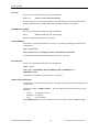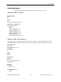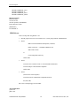
1
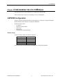
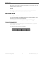
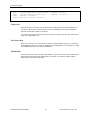
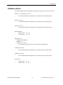
CM202
NE2000 Ethernet
utilityModule
User’s Manual
Hardware Revision 1.0
®
USA
Publication No. CM202 97.11.17
CM202
NE2000 Ethernet utilityModule
User’s Manual
REAL TIME DEVICES USA, INC.
PO Box 906
200 Innovation Blvd.
State College, PA 16804-0906 USA
Phone: (814) 234-8087
FAX: (814) 234-5218
E-Mail
[email protected]
[email protected]
Website
www.rtdusa.com
Revision History
97.11.17
Initial release.
Notice: We have attempted to verify all information in this manual as of the publication date.
Information in this manual may change without prior notice from Real Time Devices USA.
Published by
Real Time Devices USA, Inc.
200 Innovation Blvd.
P.O. Box 906
State College, PA 16804-0906 USA
Copyright 1997 by Real Time Devices USA, Inc.
All rights reserved
Printed in U.S.A.
PC/XT, PC/AT are registered trademarks of IBM Corporation.
PC/104 is a registered trademark of PC/104 Consortium.
The Real Time Devices Logo is a registered trademark of Real Time Devices.
NE2000 and NE1000 are trademarks of National Semiconductor Corportation.
utilityModule is a trademark of Real Time Devices.
Windows, Windows NT, Windows 95 are trademarks of Microsoft.
All other trademarks appearing in this document are the property of their respective owners.
Table of Contents
CHAPTER 1 INTRODUCTION ....................................................................................... 7
Features ...................................................................................................................... .............................................7
CHAPTER 2 CONFIGURING THE UTILITYMODULE ................................................... 9
EEPROM Configuration........................................................................................................................................9
Solder Jumpers .....................................................................................................................................................10
CHAPTER 3 INSTALLING THE UTILITYMODULE ..................................................... 11
Recommended Procedure.....................................................................................................................................11
CHAPTER 4 CONNECTING THE UTILITYMODULE................................................... 13
AUI connectors, J3 and J4 ...................................................................................................................................14
10Base-T connector, J5 ........................................................................................................................................16
10Base-2 connector, J6 .........................................................................................................................................17
PC/104 Bus Connectors, J1 and J2......................................................................................................................18
CHAPTER 5 USING THE UTILITYMODULE ............................................................... 21
Diagnostic LEDs....................................................................................................................................................21
Boot ROM Socket .................................................................................................................................................22
Power Consumption .............................................................................................................................................22
CHAPTER 6 SOFTWARE INSTALLATION ................................................................. 23
Software installation.............................................................................................................................................23
The Setnet Program..............................................................................................................................................23
Software drivers....................................................................................................................................................25
Server Examples....................................................................................................................................................27
Client Examples ....................................................................................................................................................29
Remote Boot Examples.........................................................................................................................................32
CHAPTER 7 REFERENCE INFORMATION................................................................. 35
Ethernet References..............................................................................................................................................35
Types of Ethernet..................................................................................................................................................35
Types of Ethernet cable........................................................................................................................................36
10Base-T Wiring Convention ..............................................................................................................................37
Ethernet frames.....................................................................................................................................................38
IEEE 802 MAC number.......................................................................................................................................38
CHAPTER 8 RETURN POLICY AND WARRANTY ..................................................... 39
Return Policy.........................................................................................................................................................39
Limited Warranty.................................................................................................................................................40
Chapter 1 INTRODUCTION
This manual gives information on the CM202 NE2000-compatible Ethernet utilityModule. This
module supports Ethernet communications using 10Base-T or 10Base-2 media, or an external
interface to 10Base-5 or optical fiber using an AUI interface.
CM202 Ethernet utilityModule
The CM202 Ethernet utilityModule was designed to provide Ethernet communications support for
the Real Time Devices CMV586DX133 cpuModule and other standard PC/104 processor
modules.
Features
The following are major features of the CM202 utilityModule.
NE2000 compatible Ethernet controller
•
LG Semicon 82C911 chipset
•
internal 16k RAM
Multiple Ethernet interfaces
•
10Base-T UTP (unshielded twisted pair)
•
10Base-2 BNC
•
AUI (DIL16 or DSUB15 connectors)
Software Configurable
•
Jumperless configuration for I/O address, interrupt, mode
•
Configuration stored in EEPROM
Boot ROM socket
•
CM202 Ethernet utilityModule
Allows remote booting of cpuModule from file server
7
Real Time Devices USA, Inc.
Features
Connectors
Connectors provided are:
•
•
•
•
•
J1 and J2, PC/104 bus
J3, AUI port (DIL)
J4, AUI port (DSUB)
J5, 10Base-T port (RJ45)
J6, 10Base-2 port (BNC)
General Specifications
•
•
•
•
•
•
•
Dimensions: 3.8 x 4.75 x 0.6" (97 x 120 x 16 mm) including connectors
Weight (mass): 3.0 ounces (85 grams)
4-layer PCB, combined through-hole and surface-mount
Operating conditions:
Remperature: 0 - 70 degrees C
Relative humidity: 0 - 95%, non-condensing
Storage temperature: -55 to +85 degrees C
CM202 Ethernet utilityModule
8
Real Time Devices USA, Inc.
User’s Manual
Chapter 2 CONFIGURING THE UTILITYMODULE
The following sections contain information on configuring the utilityModule.
Please read this entire section before attempting to use the utilityModule!
EEPROM Configuration
The most important configuration options for the module are set using the configuration program
SETNET.EXE, and then stored in a configuration EEPROM.
SETNET is used to select:
•
•
•
•
•
I/O Address
Hardware interrupt number
Media Type
Remote Boot
NE2000/1000 Compatibility Mode
Default Settings
The factory default settings for SETNET options are:
Option
I/O address
Interrupt
Media type
Remote boot
Compatibility mode
Factory Default
340h
IRQ5
10Base-T
Disabled
NE2000
Please refer to page 23 for information on changing these settings using SETNET.
CM202 Ethernet utilityModule
9
Real Time Devices USA, Inc.
Solder Jumpers
Solder Jumpers
Solder jumpers are used to configure infrequently-changed options. These include:
•
Interrupt pull-down resistors
Default Settings
The utilityModule is delivered from the factory with pull-down resistors disabled on all interrupt
lines. If you need a pull-down resistor on the interrupt line you are using, refer to the following
table for the solder jumper locations and functions.
Jumper
IRQ2
IRQ3
IRQ4
IRQ5
IRQ10
IRQ11
IRQ12
IRQ15
CM202 Ethernet utilityModule
Position
Use
jumper to apply a 1KΩ pull-down on IRQ2 line.
open: no pull-down
closed: 1KΩ pull-down
Default
open
jumper to apply a 1KΩ pull-down on IRQ3 line.
open: no pull-down
closed: 1KΩ pull-down
Default
open
jumper to apply a 1KΩ pull-down on IRQ4 line.
open: no pull-down
closed: 1KΩ pull-down
Default
open
jumper to apply a 1KΩ pull-down on IRQ5 line.
open: no pull-down
closed: 1KΩ pull-down
Default
open
jumper to apply a 1KΩ pull-down on IRQ10 line.
open: no pull-down
closed: 1KΩ pull-down
Default
open
jumper to apply a 1KΩ pull-down on IRQ11 line.
open: no pull-down
closed: 1KΩ pull-down
Default
open
jumper to apply a 1KΩ pull-down on IRQ12 line.
open: no pull-down
closed: 1KΩ pull-down
Default
open
jumper to apply a 1KΩ pull-down on IRQ15 line.
open: no pull-down
closed: 1KΩ pull-down
Default
open
10
Real Time Devices USA, Inc.
User’s Manual
Chapter 3 INSTALLING THE UTILITYMODULE
Since the utilityModule uses a PC/104 stackthrough bus, the only hardware installation you will do
is placing the module to the PC/104 stack. To do this, you will connect the PC/104 bus connector
with the matching connector of another module.
Recommended Procedure
We recommend you follow the procedure below to ensure that stacking of the modules does not
damage connectors or electronics.
•
Turn off power to the PC/104 system or stack.
•
Select and install standoffs to properly position the utilityModule on the PC/104 stack.
•
Touch a grounded metal part of the stack to discharge any buildup of static electricity.
•
Remove the utilityModule from its anti-static bag.
•
Check that keying pins in the PC/104 bus connector are properly positioned.
•
Check the stacking order: make sure an XT bus card will not be placed between two AT bus
cards, or it will interrupt the AT bus signals.
•
Hold the utilityModule by its edges and orient it so the bus connector pins line up with the
matching connector on the stack.
•
Gently and evenly press the utilityModule onto the PC/104 stack.
CAUTION: Do not force the module onto the stack! Wiggling the module or applying too much
force may damage it. If the module does not readily press into place, remove it, check
for bent pins or out-of-place keying pins, and try again.
CM202 Ethernet utilityModule
11
Real Time Devices USA, Inc.
Recommended Procedure
CM202 Ethernet utilityModule
12
Real Time Devices USA, Inc.
User’s Manual
Chapter 4 CONNECTING THE UTILITYMODULE
The following sections describe connectors of the utilityModule.
Finding Pin 1 of Connectors
Pin 1 of connectors is indicated by a square solder pad visible on the bottom of the PC board.
Component Locations
The figure below shows locations of major components, including connectors.
10Base-2, J6
LED D6
AUI Port,
J3
10Base-T, J5
AUI Port,
J4
Boot ROM
Socket
LEDs, D1-D5
XT PC/104 bus,
J1
AT PC/104 bus,
J2
Connector
J1
J2
J3
J4
J5
J6
CM202 Ethernet utilityModule
Function
XT PC/104 bus
AT PC/104 bus
AUI Port (DIL)
AUI Port (DB15)
UTP Port (RJ45)
BNC Port
13
Dimension
64 pin
32 pin
16 pin
15 pin
8 pin
2 pin
Real Time Devices USA, Inc.
AUI connectors, J3 and J4
AUI connectors, J3 and J4
Connectors J3 and J4 implement the AUI (Attachment Unit Interface). This interface can be used
to connect an external MAU (Media Attachment Unit) to convert to 10Base-5, Optical Fiber, or
another communication media.
These connectors carry the following signals:
•
•
•
•
Balanced Pair Transmit signal
Balanced Pair Receive signal
Balanced Pair Collision Detect signal
Power supply (+12Vdc from PC/104 bus) for an external transceiver
V+ Protection
The +12V output of the AUI connectors J3 and J4 are protected by F1, a 1 amp fast-acting
picofuse mounted near J3 and J4.
Pinouts
The following table gives the pinout of connector J3.
Pin
1
2
3
4
5
6
7
8
9
10
11
12
13
14
15
16
CM202 Ethernet utilityModule
Signal
GND
COLCOL+
TXTX+
GND
GND
RXRX+
+12V
GND
GND
N.C.
N.C.
GND
N.C.
Function
Ground
Collision Detect Collision Detect +
Transmit Transmit +
Ground
Ground
Receive Receive +
+12 volts DC
Ground
Ground
not connected
not connected
Ground
not connected
14
in/out
-in
in
out
out
--in
in
out
---
--
Real Time Devices USA, Inc.
User’s Manual
The following table gives the pinout of J4.
Pin
1
2
3
4
5
6
7
8
9
10
11
12
13
14
15
CM202 Ethernet utilityModule
Signal
GND
COL+
TX+
GND
RX+
GND
N.C.
GND
COLTXGND
RX+12V
GND
N.C.
Function
Ground
Collision Detect +
Transmit +
Ground
Receive +
Ground
not connected
Ground
Collision Detect Transmit Ground
Receive +12 volts DC
Ground
not connected
15
in/out
-in
out
-in
--in
out
-in
out
--
Real Time Devices USA, Inc.
10Base-T connector, J5
10Base-T connector, J5
Connector J5 is for UTP (Unshielded Twisted Pair) wiring normally used for 10Base-T Ethernet.
The following table gives the pinout of J1.
Pin
1
2
3
4
5
6
7
8
Signal
TX+
TXRX+
N.C.
N.C.
RXN.C.
N.C.
Function
Transmit +
Transmit Receive +
not connected
not connected
Receive not connected
not connected
in/out
out
out
in
in
The figure below shows the pin numbering of J5 when looking into the connector:
1 2 3 4 5 6 7 8
RJ-45 Jack Connector
J5 is a standard female RJ-45 connector. One example of a mating plug is:
•
AMP 5-554739-3 (unshielded)
CM202 Ethernet utilityModule
16
Real Time Devices USA, Inc.
User’s Manual
10Base-2 connector, J6
Connector J6 is a BNC bayonet connector for coaxial cable normally used with 10Base-2 Ethernet.
The pinout of J6 is:
Pin
1
2
Signal
SIGNAL
GND
Function
Signal to 50 ohm cable
Signal Ground
in/out
in/out
--
2
1
BNC Connector J6
CM202 Ethernet utilityModule
17
Real Time Devices USA, Inc.
PC/104 Bus Connectors, J1 and J2
PC/104 Bus Connectors, J1 and J2
Connectors J1 and J2 provide PC/104 bus connections. J1 carries XT bus signals, and J2 carries
additional signals for the AT bus. The signals on J1 and J2 conform to the IEEE P966 standard for
the PC/104 bus.
The following tables list the connector pinouts:
Pin
1
2
3
4
5
6
7
8
9
10
11
12
13
14
15
16
17
18
19
20
21
22
23
24
25
26
27
28
29
30
31
32
CM202 Ethernet utilityModule
PC/104 XT Bus Connector, J1
Row A
Row B
IOCHCHK*
SD7
SD6
SD5
SD4
SD3
SD2
SD1
SD0
IOCHRDY
AEN
SA19
SA18
SA17
SA16
SA15
SA14
SA13
SA12
SA11
SA10
SA9
SA8
SA7
SA6
SA5
SA4
SA3
SA2
SA1
SA0
0V
18
0V
RESETDRV
+5V
IRQ9
-5V
DRQ2
-12V
ENDXFR*
+12V
(KEYING PIN)
SMEMW*
SMEMR*
IOW*
IOR*
DACK3
DRQ3
DACK1*
DRQ1
REFRESH
SYSCLK
IRQ7
IRQ6
IRQ5
IRQ4
IRQ3
DACK2*
TC
BALE
+5V
OSC
0V
0V
Real Time Devices USA, Inc.
User’s Manual
Pin
0
1
2
3
4
5
6
7
8
9
10
11
12
13
14
15
16
17
18
19
Note:
PC/104 AT Bus Connector, J2
Row C
Row D
0V
SBHE*
LA23
LA22
LA21
LA20
LA19
LA18
LA17
MEMR*
MEMW*
SD8
SD9
SD10
SD11
SD12
SD13
SD14
SD15
(KEYING PIN)
0V
MEMCS16*
IOCS16*
IRQ10
IRQ11
IRQ12
IRQ15
IRQ14
DACK0*
DRQ0
DACK5*
DRQ5
DACK6*
DRQ6
DACK7*
DRQ7
+5V
MASTER*
0V
0V
Two locations on the bus have mechanical keying pins to help prevent misconnection
of the PC/104 bus. These keying pins are a part of the PC/104 standard, and we
strongly recommend you leave them in place.
If you have other modules without keying pins, we suggest you modify them to
include keying.
CM202 Ethernet utilityModule
19
Real Time Devices USA, Inc.
PC/104 Bus Connectors, J1 and J2
CM202 Ethernet utilityModule
20
Real Time Devices USA, Inc.
User’s Manual
Chapter 5 USING THE UTILITYMODULE
Using the utilityModule is straightforward, and essentially identical to any other Ethernet card.
The following sections describe:
•
•
•
Diagnostic LEDs
Boot ROM socket
Power Consumption
Diagnostic LEDs
During operation, six LEDs are used to indicate status and provide some diagnostic information in
case of malfunctions. The locations of these LEDs are shown in the figure on page 13.
LED
D1
D2
D3
D4
D5
D6
Name
COL
LNK
RXD
TXD
POL
PWR
Meaning
Collision Detected
Link established (UTP)
Receiving from network
Transmitting to network
Polarity of signal incorrect
-9 Volt Power present (BNC)
Normal State
Off
On (10Base-T only)
Flashing
Flashing
Off
On (10Base-2 only)
LED D1
D1 is normally off, and flashes when the module detects a collision on the network. Collisions may
be due to low-quality cable, which allows crosstalk between the transmit and receive pairs,
miswiring, or a malfunctioning device on the network.
LED D2
D2 is turned on when a valid 10Base-T link is detected by the chipset. It is only active when using
the 10Base-T UTP connection with link integrity checking enabled. If it is off, the UTP wiring
may be broken or incorrect, link integrity checking may be disabled, or you may be using the
10Base-2 or AUI interface.
LED D3
D3 flashes when the module detects a receive signal or senses a collision on the network cable. It
is active when using 10Base-T (UTP), 10Base-2 (BNC), or an external AUI tranceiver.
LED D4
D4 flashes when the module tries to transmit on the network. It is active when using 10Base-T
(UTP), 10Base-2 (BNC), or an external AUI tranceiver.
LED D5
CM202 Ethernet utilityModule
21
Real Time Devices USA, Inc.
Boot ROM Socket
D5 is normally off. It is turned on to indicate incorrect polarity of a received signal, which would
normally be caused by incorrect wiring.
LED D6
D6 is on when the 10Base-2 (BNC) interface is enabled. It indicates the on-board DC/DC
converter generating -9 volts for the 10Base-2 BNC interface is enabled.
Boot ROM Socket
In some applications, you may wish to use the boot ROM socket of the utilityModule to boot a
connected cpuModule from a remote server.
The socket will accomodate a 28 pin EPROM or Flash memory devices of size 8k, 16k, 32k, or
64k bytes. The device must be a byte-wide architecture.
The boot ROM feature can be enabled using the Setnet program described on page 23.
Power Consumption
Power consumption of the utilityModule depends on which Ethernet interface is used and the
degree of activity on the network.
The following table gives typical power consumption:
Configuration
Consumption
CM202 Ethernet utilityModule
AUI
TP
BNC
_______mA _______mA _______mA
22
Real Time Devices USA, Inc.
User’s Manual
Chapter 6 SOFTWARE INSTALLATION
This chapter contains information on:
•
•
•
•
•
Software installation
The Setnet Program
Server Examples
Client Examples
Client Remote Boot Examples
Software installation
There is no installation program for the supplied software. We suggest you create a directory
named /CM202 on your target drive, and copy all files and subdirectories from the supplied floppy
disk into that directory.
The Setnet Program
The /TOOLS directory of the supplied floppy disk contains the setup and diagnostic utility,
SETNET.EXE.
Running Setnet
You can run the SETNET with or without the parameters shown in the table below. If you do not
specify an I/O address, the utility looks at all possible I/O addresses.
If no module is found, the utility quits.
The factory setting of the board is at I/O address 0x360 and hardware interrupt 5.
SETNET EuroTecH srl - ver. 1.0 - 11/03/1997
ETH-2096 Network Adapter setup utility.
Use : SETNET options
I/O Base Addr | IRQ Line | Boot PROM
---------------|----------|------------------------------------------/IO=240h
| /IRQ=2
| /BP=0 - None
280h
|
3
|
1 - 8K at 0C000h
9 - 32K at 0C000h
2C0h
|
4
|
2 - 8K at 0C400h
10 - 32K at 0C800h
300h
|
5
|
3 - 8K at 0C800h
11 - 32K at 0D000h
320h
|
10 |
4 - 8K at 0CC00h
12 - 32K at 0D800h
340h
|
11 |
5 - 8K at 0D000h
13 - 64K at 0C000h
360h
|
12 |
6 - 8K at 0D400h
14 - 64K at 0D000h
|
15 |
7 - 8K at 0D800h
|
|
8 - 8K at DC000h
/CIO= Current I/O Base Addr (to skip automatic search)
Physical Layer Interface
CM202 Ethernet utilityModule
| Mode
23
Real Time Devices USA, Inc.
The Setnet Program
--------------------------------------------|------------------------/TPI
: 10BaseT Compatible Squelch Level | /NE2000 : AT only
/TPIR : 10BaseT Reduced Squelch Level
| /NE1000 : AT and XT
/THIN : Ethernet (10Base2)
|
/THICK : Ethernet (10Base5, AUI port)
|
Using Setnet
When the module is found and correctly operating, the utility displays lines indicating the active
I/O address, the interrupt, the Media Type in use, the compatibility mode selected (NE2000 or
NE1000), and the MAC address of the board.
You can use the program to change settings for I/O address, Interrupt, Media Type, Remote Boot
Prom, and compatibility mode.
What Setnet Does
When you exit Setnet, your selections for I/O address, interrupt number, media type, remote boot,
and compatibility mode are saved to an EEPROM on the utilityModule. These settings are recalled
from EEPROM whenever the module is reinitialized.
NE1000 Mode
NE1000 mode can be used to allow the utilityModule to operate with an 8-bit (XT) cpuModule. In
NE1000 mode, only IRQ2, IRQ3, IRQ4, IRQ5 are available. You cannot use IRQ10, IRQ11,
IRQ12, IRQ15 with an 8-bit system bus.
CM202 Ethernet utilityModule
24
Real Time Devices USA, Inc.
User’s Manual
Software drivers
The floppy supplied with the utilityModule contains the following (or newer) versions of drivers.
NetWare 4.x Client and Server Drivers:
•
use the NE2000/NE1000 compatible drivers provided with the Operating System
NetWare 3.x Server
•
use the NE2000/NE1000 compatible drivers provided with the Operating System
NetWare 2.x Server
•
use the NE2000/NE1000 compatible drivers provided with the Operating System
ODI Workstation:
•
•
NE2000.COM
NE1000.COM
Ver. 1.54
Ver. 1.28
NDIS Drivers 3.0
•
•
•
•
Windows for Workgroups
Windows95
Windows NT3.x, NT4.x
use the NE2000 compatible drivers provided with the Operating System
LanManager for DOS
•
use the NE2000/NE1000 compatible drivers provided with the Operating System
LanManager for OS/2
•
use the NE2000/NE1000 compatible drivers provided with the Operating System
Packet Driver
•
•
NE2000.COM
NE1000.COM
CM202 Ethernet utilityModule
Ver. 4.1
Ver. 11.5.3
25
Real Time Devices USA, Inc.
Software drivers
The directory structure of the disk is:
+---NDIS30
+---NETWARE
¦
+---NW286
¦
¦
+---FS
¦
+---NW3.X
¦
+---NW4.X
¦
+---NWODI
+---MSLANMAN.DOS
¦
+---DRIVERS
¦
+---ETHERNET
¦
¦ +---NE2000
¦
¦ +---NE1000
¦
+---NIF
+---MSLANMAN.OS2
¦
+---DRIVERS
¦
+---ETHERNET
¦
¦ +---NE2000
¦
¦ +---NE1000
¦
+---NIF
+---PACKET.DRV
+---TOOLS
CM202 Ethernet utilityModule
26
Real Time Devices USA, Inc.
User’s Manual
Server Examples
The following examples illustrates configuration of the module for use as a server.
Novell Netware 2.2
The NE2000 Netware Driver is configurable and may operate with a variety of selections for I/O
Address and Interrupt. These options should be selected via ECONFIG, DCONFIG and NETGEN
(for 2.15) or INSTALL (for 2.2) utilities, which are provided with the Netware distribution
diskettes.
To generate the 2.15 dedicated server from an existing Network Disk:
1) Create NET$OS. This can be done from any station attached to the network server.
• run netgen:
• -Select Network Configuration (Our driver)
• -Link/Configure Netware Operating System
2) Now that NET$OS has been generated, do the Netware Installation.
On the server PC you are configuring:
•
•
•
•
boot DOS from a floppy
login to the network server
run netgen and select Netware Installation
reboot from hard disk
To generate the 2.2 server from an existing Network Disk:
•
•
•
•
Boot DOS from a floppy
login to the network server
Run install (when prompted to, select NE2000 driver)
reboot from hard drive
Novell Netware 3.x/4.x
Use the install.nlm utility loaded from the server console, "load ...\install", to create an autoexec
file as shown below:
AUTOEXEC.NCF
file server name BIGKAHOONAS
ipx internal net 10
load c:\ne2000 PORT=360 INT=5
bind ipx to ne2000 net=1
mount all
Typing SERVER at the DOS prompt will load the server and our driver.
Be sure ne2000.lan is in the c:\ directory
Driver configurable options are:
CM202 Ethernet utilityModule
27
Real Time Devices USA, Inc.
Server Examples
IO BASE
May be set by including the following in the command line:
Port = xxx
;where xxx can be 300, 320, 340, 360
Be sure the board is set to the same I/O address, otherwise the driver won't find the board and the
message "Hardware Error - NE2000 Bank Select port failed to respond." will appear.
INTERRUPT NUMBER
May be set by including the following in the command line:
Int = x
;where x can be 2, 3, 4, 5, 10, 11, 12, 15
Defaults to EEPROM configuration if not present
NODE ADDRESS
The board has a unique IEEE address, but it may be overwritten by including the following in the
command line:
Node = xxxxxxxxxxxx
Where xxxxxxxxxxxx is a 12 digit hex number (non-multicast or broadcast)
The default is the board's unique IEEE address if this line is not present.
FRAME TYPE
May be set by including the following in the command line
Frame = <type>
where <type> is ETHERNET_802.3, ETHERNET_802.2, ETHERNET_II,
ETHERNET_SNAP
This defaults to ETHERNET_802.3 if the line is not present.
MEDIA TYPE SELECTION
The user may select the media type to be used. This option is specified via parameter passing in the
command line.
The parameter name is "MEDIA_TYPE=" . The value following the keyword must be one of the
following:
• "AUTO"
for automatic selection.
• "10BASET" for 10BaseT.
• "AUI”
for AUI interface.
If the MEDIA_TYPE keyword is not present the driver will use the module’s EEPROM default.
CM202 Ethernet utilityModule
28
Real Time Devices USA, Inc.
User’s Manual
Client Examples
The following examples illustrates configuration of the module for use as a client.
ODI Drivers (IPX for NetWare)
STARTNET.BAT
cd\net
lsl
ne2000
ipxodi
netx /PS=Server_neme Login_name
NET.CFG (in c:\net directory)
LINK DRIVER NE2000
PORT 360
INT 5
FRAME ETHERNET_802.3
FRAME ETHERNET_II
FRAME ETHERNET_802.2
FRAME ETHERNET_SNAP
MEDIA_TYPE AUI
NODE ADDRESS EC1000013114
ODI Drivers (IPX for MS Windows)
In this examples we have used the ODI drivers that are used by NetWare too. You can find them in the directory
\NETWARE\NWODI\ of the drivers floppy disk. Windows for workgroup see them as “IPX monolitic” drivers.
AUTOEXEC.BAT
@echo off
path C:\WFW.DOS;c:\;c:\dos
prompt $p$g
cd\WFW.DOS
lsl
ne2000
ipxodi
net start
CONFIG.SYS
files=40
buffers=40
device=C:\WFW.DOS\ifshlp.sys
LASTDRIVE=Z
NET.CFG
Link Support
buffers 8 850
LINK DRIVER NE2000
PORT 360
INT 5
CM202 Ethernet utilityModule
29
Real Time Devices USA, Inc.
Client Examples
FRAME ETHERNET_802.3
FRAME ETHERNET_II
FRAME ETHERNET_802.2
FRAME ETHERNET_SNAP
PROTOCOL.INI
[network.setup]
version=0x3110
netcard=ipxmono,1,IPXMONO,1
lana0=ipxmono,1,mono
[IPXMONO]
LANABASE=0
NDIS Drivers
Create a startup disk using WinNT 3.50:
•
Run the program Network Client Administrator (in the group Network Administration).
•
choose:
Make Network Installation Startup Disk (Continue)
Path E:\Clients (E: = CD-ROM di WINNT3.50)
Share Name Clients
or
Use Existing Share Directory
and hit (OK)
•
choose:
Network Client: Network Client v3.0 for MS-DOS and Windows
Network Adapter Card: NE2000 compatible
and hit (OK)
•
choose:
(name for the client computer)
Network Protocol: NWLink IPX Compatible Protocol
hit (OK) (OK)
this creates a startup floppy for the module.
AUTOEXEC.BAT
@echo off
path=a:\net
CM202 Ethernet utilityModule
30
Real Time Devices USA, Inc.
User’s Manual
a:\net\net initialize
a:\net\nwlink
a:\net\net start
net use z: \\SERVER_NT\Clients
echo Running Setup...
z:\msclient\netsetup\setup.exe /$
CONFIG.SYS
files=30
device=a:\net\ifshlp.sys
lastdrive=z
DEVICE=A:\NET\HIMEM.SYS
DEVICE=A:\NET\EMM386.EXE NOEMS
DOS=HIGH,UMB
PROTOCOL.INI
[network.setup]
version=0x3110
netcard=ms$ne2clone,1,MS$NE2CLONE,1
transport=ms$ndishlp,MS$NDISHLP
transport=ms$nwlink,MS$NWLINK
lana0=ms$ne2clone,1,ms$nwlink
lana1=ms$ne2clone,1,ms$ndishlp
[ms$ne2clone]
drivername=MS2000$
INTERRUPT=5
IOBASE=0x360
; SlotNumber=1
[protman]
drivername=PROTMAN$
PRIORITY=MS$NDISHLP
[MS$NDISHLP]
drivername=ndishlp$
BINDINGS=ms$ne2clone
[ms$nwlink]
drivername=nwlink$
FRAME=Ethernet_802.2
BINDINGS=ms$ne2clone
LANABASE=0
Packet Drivers
The packet driver is loaded using the following syntax:
NE2000 [-n] [-d] [-w] <packet_int_no> <int_level> <io_addr>
Using the default settings, this would be entered as:
CM202 Ethernet utilityModule
31
Real Time Devices USA, Inc.
Remote Boot Examples
NE2000 0x60 0x5 0x340
If the use of ODI drivers is requested or preferred, it is possible to use the ODI packet driver:
LSL
NE2000
IPXODI
ODIPKT 1 0x60
NET.CFG
LINK SUPPORT
buffers 8 850
LINK DRIVER NE2000
PORT 360
INT 5
FRAME ETHERNET_802.3
FRAME ETHERNET_II
FRAME ETHERNET_802.2
FRAME ETHERNET_SNAP
PROTOCOL IPX 0 ETHERNET_802.3
Remote Boot Examples
The following examples illustrate configuration of the module for use in a remote boot application.
RPL from a WindowsNT server 3.5
1. Install RPL Service on your WindowsNT Server
2. Copy DOS 6.22 files in WINNT35\RPL\RPLFILES\BINFILES\DOS622
3. Copy NE2000.DOS in WINNT35\RPL\BBLOCKS\NDIS;
remember not to flag the files IO.SYS and MSDOS.SYS as Hidden or System.
4. From a DOS window run RPLCMD
5. add Vendor:
VendorName=00E0C7
comment=Eurotech NE2000
6. add boot (b - a):
BootName= DOS
VendorName=00E0C7
BBCFile=BBLOCK\NETBEUI\NE2000\DOSBB.CNF
7. Restart WindowsNT and start RPL Service.
Now the cpuModule used with the utilityModule can remotely boot DOS from WindowsNT Server
DOSBB.CNF
; DOS on NE2000 Ethernet
BASE D0H
RPL BBLOCK\RPLBOOT.SYS
LDR BBLOCK\RPLSTART.COM ~
DAT BBLOCK\NETBEUI\NE2000\PROTOCOL.INI
DRV BBLOCK\RPLDISK.SYS ~ ~ ~
EXE BBLOCK\RPLPRO1.COM ~ 2 ~
CM202 Ethernet utilityModule
32
Real Time Devices USA, Inc.
User’s Manual
EXE BBLOCK\I13.COM ~ ~ ~
EXE BBLOCK\RPLBIND2.EXE ~ ~
EXE BBLOCK\PROTMAN.EXE ~ ~
EXE BBLOCK\RPLBIND1.EXE ~ ~
;DRV BBLOCK\IPXNDIS.DOS ~ ~ ~
;DRV BBLOCK\TCPDRV.DOS /I:C:\LANMAN.DOS ~ ~
EXE BBLOCK\NETBEUI\NETBEUI.EXE ~ 10 ~
DRV BBLOCK\NDIS\NE2000.DOS ~ ~ ~
DRV BBLOCK\PROTMAN.DOS /I:C:\LANMAN.DOS ~ M
PROTOCOL.INI
[protman]
drivername = protman$
dynamic = yes
priority = netbeui
[netbeui_xif]
drivername = netbeui$
bindings = ne2000_nif
names = 6
ncbs = 12
packets = 20
pipeline = 10
sessions = 6
stacksize = 512
lanabase = 0
[xnsnb_xif]
drivername = xnsnb$
bindings = ne2000_nif
load = xnsnb[cbr]
lanabase = 1
[xnstp_xif]
drivername = xnstp$
bindings = ne2000_nif
load = xnstp[ub]
lanabase = 1
[tcpip_xif]
drivername = TCPIP$
disabledhcp = (TCPIP_NO_DHCP)
ipaddress0 = (TCPIP_ADDRESS)
subnetmask0 = (TCPIP_SUBMASK)
defaultgateway0 = (TCPIP_GATEWAY)
tcpsegmentsize = 1450
tcpwindowsize = 1450
nbsessions = 6
load = tcptsr[c],tinyrfc[c],emsbfr[cr]
unload = "unloadt /notsr[dc]"
bindings = ne2000_nif
lanabase = 1
CM202 Ethernet utilityModule
33
Real Time Devices USA, Inc.
Remote Boot Examples
[ipx_xif]
drivername = ipx$
load = ipxmark[u],ipx[u]
unload = ipxrel[c]
bindings = ne2000_nif
lanabase = 1
[msdlc_xif]
drivername = msdlc$
bindings = ne2000_nif
load = msdlc[ub]
unload = msdlc[u]
[ne2000_nif]
drivername = NE2$
INTERRUPT=5
IOBASE = 0x360
CM202 Ethernet utilityModule
34
Real Time Devices USA, Inc.
User’s Manual
Chapter 7 REFERENCE INFORMATION
This chapter contains reference information concerning:
•
•
•
•
•
Ethernet References
Types of Ethernet
Types of Ethernet Cable
Ethernet Frames
IEEE 802 MAC Number
Ethernet References
To learn more about Ethernet, you might start with:
Charles Spurgeon’s Ethernet Website:
http:wwwhost.ots.utexas.edu/ethernet/ethernet-home.html
This site provides thorough overviews of 10 Mbps and faster Ethernet.
Types of Ethernet
There are three standard types of 10 Megabit Ethernet, of which 10Base-T is by far the most
common, and 10Base-5 is by far the least common.
Ethernet
Type
Nickname
Data transfer
rate
Topology
Cable type
10Base-T
“Cheapernet”
10 Mbps
Star
10Base-2
“Thin” Ethernet
10 Mbps
Bus
100 ohm UTP
(unshielded
twisted pair)
RG-58 coaxial
10Base-5
“Thick”
Ethernet
10 Mbps
Bus
RG-11 coaxial
CM202 Ethernet utilityModule
35
Maximum
Segment
length
100 m
328 ft
185 m
607 ft
500 m
1640 ft
Real Time Devices USA, Inc.
Types of Ethernet cable
Types of Ethernet cable
Ethernet uses one of three standard cable types:
Ethernet
Type
10Base-T
10Base-2
10Base-5
Cable type
Impedance
Denomination
UTP
RG-58
RG-11
100 Ohm
50 Ohm
50 Ohm
unshielded twisted pair
Ethernet thin
Ethernet thick (yellow
cable)
Note: Although 8-conductor telephone wire is commonly used for 10Base-T connections, this type
wire is not the correct 100 ohm UTP, as it does not use twisted-pairs. Using such wire may cause
excessive crosstalk, resulting in a large number of collisions and poor network performance.
CM202 Ethernet utilityModule
36
Real Time Devices USA, Inc.
User’s Manual
10Base-T Wiring Convention
10Base-T Ethernet uses the following wiring convention when connecting a node to a hub. It is
suggested you use this convention for consistency:
RJ45 PIN
1
2
3
4
5
6
7
8
Note:
CM202 Ethernet utilityModule
First End
Pair No.
wire color
3
3
2
1
1
2
4
4
W-G
G
W-O
BL
W-BL
O
W-BR
BR
Second End
Pair No. wire color
to
to
to
to
to
to
to
to
2
2
3
1
1
3
4
4
W-O
O
W-G
BL
W-BL
G
W-BR
BR
RJ45
PIN
1
2
3
4
5
6
7
8
W-G = White-Green
G
= Green
W-O = White-Orange
O
= Orange
W-BL = White-Blue
BL
= Blue
W-BR = White-Brown
BR
= Brown
37
Real Time Devices USA, Inc.
Ethernet frames
Ethernet frames
The following are standard Ethernet frames.
•
•
•
•
ETHERNET_II
ETHERNET_802.3
ETHERNET_802.2
ETHERNET_SNAP
Primarily used by TPC/IP
Default frame for Netware 3.11
Default frame for Netware 3.12 and 4.x
Primarily used by Appletalk
IEEE 802 MAC number
The CM202 utilityModule is identified with an Organizationally Unique Identifier (OUI) and
company_id number:
00-E0-C7
The MAC (Media Access Control) number of the utilityModule is thus:
00-E0-C7-xx-xx-xx
where the last three bytes are the serial number of the board, unique for each adapter.
CM202 Ethernet utilityModule
38
Real Time Devices USA, Inc.
User’s Manual
Chapter 8 RETURN
POLICY AND WARRANTY
Return Policy
If the utilityModule requires repair, you may return it to us by following the procedure listed
below:
Caution:
Failure to follow this return procedure will almost always delay repair! Please help us
expedite your repair by following this procedure.
1) Read the limited warranty which follows.
2) Contact the factory and request a Returned Merchandise Authorization (RMA) number.
3) On a sheet of paper, write the name, phone number, and fax number of a technically-competent
person who can answer questions about the problem.
4) On the paper, write a detailed description of the problem with the product. Answer the following
questions:
• Did the product ever work in your application?
• What other devices were connected to the product?
• How was power supplied to the product?
• What features did and did not work?
• What was being done when the product failed?
• What were environmental conditions when the product failed?
5) Indicate the method we should use to ship the product back to you.
•
•
•
We will return warranty repairs by UPS Ground at our expense.
Warranty repairs may be returned by a faster service at your expense.
Non-warranty repairs will be returned by UPS Ground or the method you select, and
will be billed to you.
6) Clearly specify the address to which we should return the product when repaired.
7) Enclose the paper with the product being returned.
8) Carefully package the product to be returned using anti-static packaging! We will not be
responsible for products damaged in transit for repair.
7) Write the RMA number on the outside of the package.
8) Ship the package to:
Real Time Devices
200 Innovation Blvd.
State College PA 16803
USA
CM202 Ethernet utilityModule
39
Real Time Devices USA, Inc.
Limited Warranty
Limited Warranty
Real Time Devices, Inc. warrants the hardware and software products it manufactures and
produces to be free from defects in materials and workmanship for one year following the date of
shipment from REAL TIME DEVICES. This warranty is limited to the original purchaser of
product and is not transferable.
During the one year warranty period, REAL TIME DEVICES will repair or replace, at its option,
any defective products or parts at no additional charge, provided that the product is returned,
shipping prepaid, to REAL TIME DEVICES. All replaced parts and products become the property
of REAL TIME DEVICES. Before returning any product for repair, customers are required to
contact the factory for an RMA number.
THIS LIMITED WARRANTY DOES NOT EXTEND TO ANY PRODUCTS WHICH HAVE
BEEN DAMAGED AS A RESULT OF ACCIDENT, MISUSE, ABUSE (such as: use of incorrect
input voltages, improper or insufficient ventilation, failure to follow the operating instructions that
are provided by REAL TIME DEVICES, "acts of God" or other contingencies beyond the control
of REAL TIME DEVICES), OR AS A RESULT OF SERVICE OR MODIFICATION BY
ANYONE OTHER THAN REAL TIME DEVICES. EXCEPT AS EXPRESSLY SET FORTH
ABOVE, NO OTHER WARRANTIES ARE EXPRESSED OR IMPLIED, INCLUDING, BUT
NOT LIMITED TO, ANY IMPLIED WARRANTIES OF MERCHANTABILITY AND
FITNESS FOR A PARTICULAR PURPOSE, AND REAL TIME DEVICES EXPRESSLY
DISCLAIMS ALL WARRANTIES NOT STATED HEREIN. ALL IMPLIED WARRANTIES,
INCLUDING IMPLIED WARRANTIES FOR MECHANTABILITY AND FITNESS FOR A
PARTICULAR PURPOSE, ARE LIMITED TO THE DURATION OF THIS WARRANTY. IN
THE EVENT THE PRODUCT IS NOT FREE FROM DEFECTS AS WARRANTED ABOVE,
THE PURCHASER'S SOLE REMEDY SHALL BE REPAIR OR REPLACEMENT AS
PROVIDED ABOVE. UNDER NO CIRCUMSTANCES WILL REAL TIME DEVICES BE
LIABLE TO THE PURCHASER OR ANY USER FOR ANY DAMAGES, INCLUDING ANY
INCIDENTAL OR CONSEQUENTIAL DAMAGES, EXPENSES, LOST PROFITS, LOST
SAVINGS, OR OTHER DAMAGES ARISING OUT OF THE USE OR INABILITY TO USE
THE PRODUCT.
SOME STATES DO NOT ALLOW THE EXCLUSION OR LIMITATION OF INCIDENTAL
OR CONSEQUENTIAL DAMAGES FOR CONSUMER PRODUCTS, AND SOME STATES
DO NOT ALLOW LIMITATIONS ON HOW LONG AN IMPLIED WARRANTY LASTS, SO
THE ABOVE LIMITATIONS OR EXCLUSIONS MAY NOT APPLY TO YOU.
THIS WARRANTY GIVES YOU SPECIFIC LEGAL RIGHTS, AND YOU MAY ALSO HAVE
OTHER RIGHTS WHICH VARY FROM STATE TO STATE.
CM202 Ethernet utilityModule
40
Real Time Devices USA, Inc.