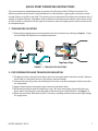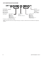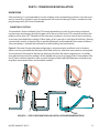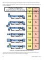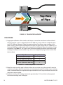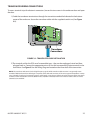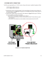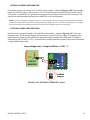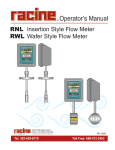
1
DDFXD Doppler Ultrasonic Flow Meter FORM # 06-DPP-UM-00147 RUN Tel: 262-639-6770 Toll Free: 800-535-3569 TABLE OF CONTENTS SYMBOL EXPLANATIONS .................................................................................................6 QUICK-START OPERATING INSTRUCTIONS ...................................................................7 1 - TRANSDUCER LOCATION ...................................................................................................................7 2 - PIPE PREPARATION AND TRANSDUCER MOUNTING .......................................................................7 3 - TRANSDUCER CONNECTIONS ...........................................................................................................8 4 - STARTUP .............................................................................................................................................8 PART 1 - INTRODUCTION .................................................................................................9 GENERAL .................................................................................................................................................9 APPLICATION VERSATILITY ....................................................................................................................9 USER SAFETY .........................................................................................................................................10 DATA INTEGRITY ...................................................................................................................................10 PRODUCT IDENTIFICATION ..................................................................................................................10 PRODUCT MATRIX.................................................................................................................................11 PART 2 - TRANSDUCER INSTALLATION .........................................................................13 UNPACKING ...........................................................................................................................................13 PIPE PREPARATION ...............................................................................................................................15 COUPLANT.............................................................................................................................................15 DT9 CLAMP-ON TRANSDUCER MOUNTING ........................................................................................15 DP7 PROBE TRANSDUCER MOUNTING ...............................................................................................17 PART 3 - TRANSMITTER INSTALLATION........................................................................23 UNPACKING ...........................................................................................................................................23 MOUNTING LOCATION .........................................................................................................................23 TRANSDUCER WIRING CONNECTIONS ................................................................................................25 POWER SUPPLY WIRING CONNECTIONS .............................................................................................26 MULTIPLE METER INSTALLATIONS.......................................................................................................30 ISO MODULES ........................................................................................................................................31 PART 4 – INSTRUMENT PROGRAMMING ......................................................................37 GENERAL ...............................................................................................................................................37 KEYPAD OPERATION .............................................................................................................................37 PART 5 - STARTUP AND TROUBLESHOOTING ..............................................................50 DFX START-UP REQUIREMENTS ...........................................................................................................50 TROUBLESHOOTING .............................................................................................................................51 06-DPP-UM-00147 02/12 3 APPENDIX ........................................................................................................................53 SPECIFICATIONS ...................................................................................................................................53 MENU MAPS ..........................................................................................................................................55 PIPE TABLES...........................................................................................................................................58 LIMITED WARRANTY AND DISCLAIMER .......................................................................62 WASTE ELECTRICAL AND ELECTRONIC EQUIPMENT (WEEE) DIRECTIVE .................63 RETURN/SALES INFORMATION CONTACTS AND PROCEDURES ................................64 4 06-DPP-UM-00147 02/12 FIGURES FIGURE 1.1 - TRANSDUCER LOCATIONS ................................................................................................7 FIGURE 1.2 - TRANSDUCER DIRECTION .................................................................................................8 FIGURE 2.1 - PIPE CONFIGURATIONS AND INSTALLATION RECOMMENDATIONS ...........................13 FIGURE 2.2 - UPSTREAM/DOWNSTREAM PIPE REQUIREMENTS ........................................................14 FIGURE 2.3 - TRANSDUCER PLACEMENT .............................................................................................16 FIGURE 2.5 - HOT TAP INSTALLATION ..................................................................................................18 FIGURE 2.4 - INSTALLATION LOCATIONS .............................................................................................18 FIGURE 2.6 - INSTALLATION MEASUREMENTS ....................................................................................20 FIGURE 2.7 - FLOW DIRECTION ARROW ..............................................................................................21 FIGURE 3.1 - DFX TRANSMITTER INSTALLATION DIMENSIONS .........................................................24 FIGURE 3.2 - TRANSDUCER CABLE INSTALLATION .............................................................................25 FIGURE 3.3 - TRANSDUCER CONNECTIONS.........................................................................................26 FIGURE 3.4 - DXF WIRING DIAGRAM ....................................................................................................27 FIGURE 3.5 - DFX AC POWER CONNECTION ........................................................................................28 FIGURE 3.6 - DC POWER CONNECTION ................................................................................................29 FIGURE 3.7 - METER SYNCHRONIZATION DETAIL ...............................................................................30 FIGURE 3.8 - DFX SYNCHRONIZATION CONNECTIONS .......................................................................31 FIGURE 3.9 - TWO ISO-MOD I/O MODULES INSTALLED ......................................................................32 FIGURE 3.10A - MAXIMUM 4-20 MA LOADS.........................................................................................32 FIGURE 3.10B - INTERNALLY POWERED 4-20 mA ................................................................................33 FIGURE 3.10C - EXTERNALLY POWERED 4-20 mA ...............................................................................34 FIGURE 3.11A - TYPICAL RELAY CONNECTIONS .................................................................................34 FIGURE 3.11B - EXTERNAL RELAY CONNECTIONS ..............................................................................35 FIGURE 3.12 - RATE PULSE MODULE ....................................................................................................36 FIGURE 4.1 - KEYPAD LAYOUT ..............................................................................................................37 FIGURE 4.2 - 4-20 mA CALIBRATION SETUP ........................................................................................43 FIGURE 4.3 - SINGLE POINT ALARM OPERATION ................................................................................45 FIGURE 4.4 - DIAGNOSTIC DISPLAY .....................................................................................................47 FIGURE A-1.1 - MENU MAP -- 1 .............................................................................................................55 FIGURE A-1.2 - MENU MAP -- 2 .............................................................................................................56 06-DPP-UM-00147 02/12 5 TABLES TABLE 2.1 - STRAPS REQUIRED VS. PIPE SIZE ......................................................................................16 TABLE 4.1 - EXPONENT VALUES ............................................................................................................40 TABLE A 1.1 - SPECIFICATIONS ............................................................................................................54 TABLE A 2.1 - FLUID PROPERTIES ........................................................................................................58 TABLE TABLE TABLE TABLE A 3.1 - STEEL, STAINLESS STEEL, P.V.C. PIPE ............................................................................60 A 3.2 - TUBE DATA......................................................................................................................62 A 3.3 - DUCTILE IRON PIPE (STANDARD CLASSES) ..................................................................63 A 3.4 - CAST IRON PIPE (STANDARD CLASSES)........................................................................64 SYMBOL EXPLANATIONS Caution - Refer to accompanying documents. Electrical Caution - Refer to accompanying documents. FLOW METER INSTALLATION WARNING: DO NOT CONNECT OR DISCONNECT EITHER POWER OR OUTPUTS UNLESS THE AREA IS KNOWN TO BE NON-HAZARDOUS. AVERTISSMENT: RISQUE D’EXPLOSION. NE PAS DÉBRANCHER TANT QUE LE CIRCUIT EST SOUS TENSION, À MOINS QU’lL NE S’AGISSE D’UN EMPLACEMENT NON DANGEREUX. IMPORTANT NOTE: Not following instructions properly may impair safety of equipment and/or personnel. ELECTRICAL SYMBOLS Function Direct Current Alternating Current Earth (Ground) Protective Ground Chassis Ground Symbol 6 06-DPP-UM-00147 02/12 QUICK-START OPERATING INSTRUCTIONS This manual contains detailed operating instructions for all aspects of the DFX flow instrument. The following condensed instructions are provided to assist the operator in getting the instrument started up and running as quickly as possible. This pertains to basic operation of the clamp-on transducer only. If specific instrument features, a hazardous area installation or an alternate transducer style are to be used; or if the installer is unfamiliar with this type of instrument, refer to the appropriate section in the manual for complete details. 1 - TRANSDUCER LOCATION 1) Determine the appropriate mounting location for the transducers by referring to Figure 1.1. Pipe must be filled with liquid to ensure proper operation. h h FLOW Top View of Pipe FIGURE 1.1 - TRANSDUCER LOCATIONS 2 - PIPE PREPARATION AND TRANSDUCER MOUNTING 1) The piping surface, where the transducers are to be mounted, needs to be clean and dry. Remove loose scale, rust and paint to ensure satisfactory acoustical bonds. 2) Connect the mounting straps around the pipe. Leave the strap loose enough to slip the transducers underneath. 3) Apply a liberal amount of couplant grease onto the transducer faces. 4) Place each transducer under the mounting strap, 180° apart on the pipe. Ensure that the transducer cables are facing the same direction on the downstream side of the flow. See Figure 1.2. 5) Route the transducer cable back to the DFX monitor, avoiding conduits that contain high voltage AC supply wires. 06-DPP-UM-00147 02/12 7 FLOW Top View of Pipe FIGURE 1.2 - TRANSDUCER DIRECTION 3 - TRANSDUCER CONNECTIONS 1) Mount DFX monitor within the length of the transducer cables. While transducer cable extension is not generally recommended, if additional transducer cable length is required, utilize cable and connectors of the correct type and impedance. In many cases, especially if a splice my be exposed to water or other liquids, it may be more effective to replace the entire cable. Transducers use RG59 ,75 ohm coaxial cable or Twinax (Belden #9463) or (Belden # 9463DB) 78 Ohm two conductor cable. 2) Route the transducer cables through the center conduit hole in the bottom of the DFX enclosure and connect to terminal block J4. The terminal blocks are a removable and can be disconnected to simplify wiring access. A wiring diagram is located on the inner door for reference. 4 - STARTUP INITIAL SETTINGS AND POWER UP 1) Verify that the DFX power supply jumper settings are properly configured for the power supply that will be utilized. A wiring and jumper selection diagram is located on the inner door for reference. NOTE: Power supply selection is specified during order placement and appropriate jumpers are placed at the factory. If power is changed from AC to DC or vice versa, the fuse requirement will change. Fuse ratings are listed on the transmitter’s door. 2) Route power connections through the conduit hole farthest to the left and in the DFX enclosure. Then connect power to the J2 terminal block. See Figure 3.2. 3) Apply power. 4) On initial power-up, the DFX conducts a series of self-diagnostic tests and buffering operations that take approximately 30 seconds. 5) Enter pipe internal diameter (Pipe ID), measuring units and output configuration. 8 06-DPP-UM-00147 02/12 PART 1 - INTRODUCTION GENERAL The DFX ultrasonic flow meter is designed to measure volumetric flow of solids-bearing or aerated liquid within closed conduit. Transducers are available as non-contacting (DT9) or insertion probe (DP7) types. DT9 non-contacting transducers are strapped to the outside of a pipe and are suitable for most installations where the pipe material supports the transmission of ultrasound. Some pipe materials, such as concrete pressure pipe and some plastic lined pipes do not allow ultrasound to penetrate to the liquid inside. For these applications, the DP7 insertion probe will be needed. The flow meter operates by transmitting an ultrasonic sound from its transmitting transducer through the pipe wall or from the probe tip into the moving liquid. The sound will be reflected by useful sonic reflectors1 suspended within the liquid and recorded by the receiving transducer. If the sonic reflectors are moving within the sound transmission path, sound waves will be reflected at a frequency shifted (Doppler frequency) from the transmitted frequency. The shift in frequency will be directly related to the speed of the moving particle or bubble. This shift in frequency is interpreted by the instrument and converted to various user defined measuring units. 1 What makes a good Doppler reflector? The four criteria are: t The scattering material must have a sonic impedance (sound speed difference) at least 10% different from the fluid. t There must be some particles large enough to cause longitudinal reflection – particles larger than 35 micron. t For a given pipe size, the longitudinal reflection must have sufficient energy to overcome the Rayleigh (energy wasting) scattering caused by smaller particles. t The reflecting material must travel at the same velocity as the fluid for good accuracy. APPLICATION VERSATILITY The DFX flow meter can be successfully applied on a wide range of metering applications. The easy to program transmitter allows the standard product to be used on pipe sizes ranging from 1” - 120” (25 mm - 3050 mm) pipe I.D. With the small pipe transducer option, the pipe size range is 0.25” - 1” (6 mm - 25 mm). A variety of liquid applications can be accommodated: sewage plant effluent sludge river water mining slurries others Because the transducers are non-contacting and have no moving parts, the flow meter is not affected by system pressure, fouling or wear. Standard transducers are rated to a pipe surface temperature of 250 °F (121 °C). Optional high temperature transducers are rated to operate to a pipe surface temperature of 400 °F (204 °C). 06-DPP-UM-00147 02/12 9 USER SAFETY The DFX employs modular construction and provides electrical safety for the operator. The enclosure is constructed from rugged polycarbonate plastic with UV inhibitors. The enclosure does not contain any conductive materials that can become energized while the door is closed. The keypad is also manufactured from polycarbonate and is designed for outdoor use. The AC power transformer provides 4,000 Volts of isolation from the power supply mains. The display face contains voltages no greater than 24 VDC. Output modules are optically isolated from external power supplies and provide a great degree of immunity to ground loops. CAUTION: If the DFX is used in a manner not specified by the manufacturer, the protection provided by the equipment may be impaired. DATA INTEGRITY The DFX product retains all user configuration data and totalizer accumulations in non-volatile FLASH memory indefinitely. PRODUCT IDENTIFICATION The serial number and complete model number of the transmitter are located on the side of the monitor enclosure. Should technical assistance be required, please provide the Customer Service Department with this information. 10 Model: SN: Date Of Manufacture: Rating: 115VAC 50-60 Hz @ 17VA Scale Factor: Pipe Size: Output: 4mA: 20mA: CAUTION: Equipment must be isolated or disconnected from hazardous line voltage before opening enclosure. ATTENTION: Équipement doit être isolé ou déconnecté de la tension d’alimentation dangereux avant d’ourir la pièce jointe. Model: SN: Date Of Manufacture: Rating: 12-28 VDC 7W Scale Factor: Pipe Size: Output: 4mA: 20mA: CAUTION: Equipment must be isolated or disconnected from hazardous line voltage before opening enclosure. ATTENTION: Équipement doit être isolé ou déconnecté de la tension d’alimentation dangereux avant d’ourir la pièce jointe. ELECTRICAL SAFETY E113055 ELECTRICAL SAFETY E113055 06-DPP-UM-00147 02/12 PRODUCT MATRIX DDFXD DIGITAL DOPPLER ULTRASONIC FLOW TRANSMITTER DDFXD 2 - A-NN Transmitter Type Options 2) Rate and Totalizer N) None Approvals N) General Safety, CE Approved Power Supply A) 115 VAC B) 230 VAC C) 100 VAC E) 12-28 VDC Totalizer Input/Output 1 N) None 1) 4-20 mA 2) Dual Relay 3) Rate Pulse A) Eight Digit Resettable Input/Output 2 N) None 1) 4-20 mA 2) Dual Relay 3) Rate Pulse DT9 CLAMP-ON DOPPLER TRANSDUCER SET DT9 N Transmitter Type* Approvals 4) Std. Temp/Std. Pipe 5) Std. Temp/Small Pipe 6) High Temp/Std. Pipe 7) High Temp/Small Pipe N) General Safety to US/Canadian standards Cable Length Conduit Type Conduit Length 000) 0’ (0m) 020) 20’ (6m) 050) 50’ (15m) 100) 100’ (30m) N) None A) Flexible Armored 000) 0’ (0m) 020) 20’ (6m) 050) 50’ (15m) 100) 100’ (30m) Maximum length : 990’ (300m) in 10’ (3m) increments Maximum length : 990’ (300m) in 10’ (3m) increments *Std Temp: Maximum +250 °F (+121 °C) High Temp: Maximum +400 °F (+204 °C) Std Pipe: 1” (25 mm) and above Small Pipe: ¼” to 1” (6 mm to 25 mm) 06-DPP-UM-00147 02/12 11 DP7 INSERTION DOPPLER PROBE DP7 N Probe Length Approvals 1) 8” (203 mm)* 2) 18” (457 mm) 3) 28” (711 mm) 4) 38” (965 mm) 5) 48” (1220 mm) N) General Safety to US/Canadian standards B) 1½” RF flange, General Safety Consult Factory for Longer Lengths Cable Length Conduit Type Conduit Length 000) 0’ (0m) 020) 20’ (6m) 050) 50’ (15m) 100) 100’ (30m) N) None A) Flexible Armored 000) 0’ (0m) 020) 20’ (6m) 050) 50’ (15m) 100) 100’ (30m) Maximum length : 990’ (300m) in 10’ (3m) increments Maximum length : 990’ (300m) in 10’ (3m) increments *Cannot be used with hot tap assembly NOTE: All DP7 probes include a seas fitting for mounting in 1½” NPT ports. Isolation valve kits are available for hot-tapped applications. 12 06-DPP-UM-00147 02/12 PART 2 - TRANSDUCER INSTALLATION UNPACKING After unpacking, it is recommended to save the shipping carton and packing materials in case the instrument is stored or re-shipped. Inspect the equipment and carton for damage. If there is evidence of shipping damage, notify the carrier immediately. MOUNTING LOCATIONS The transducers that are utilized by the DFX contain piezoelectric crystals for transmitting and receiving ultrasonic sound energy through the pipe wall in the case of the series DT9 transducer and from the probe tip of the series DP7. Placement of the ultrasonic transducer is the most critical step in achieving an accurate and reliable flow reading. All flow meters of this type rely on a full-pipe of fluid that is flowing symmetrically (evenly) in the pipe. Flow in partially filled pipes and immediately downstream of elbows, valves and pumps is unstable and will lead to unstable readings and non-linearity. h h Figure 2.1 illustrates five possible pipe configurations and recommends installation only in locations where it can be guaranteed that the pipe will be filled at all times when flow measurements are required. The two locations illustrated in the top two drawings may allow the meter to operate, but it is unlikely that stable and accurate flow readings will be realized over a very large range of flow. Since products like the DFX have software algorithms that assume a full-pipe of liquid, partially-filled pipes can lead to very large flow measurement errors and should be avoided. FIGURE 2.1 - PIPE CONFIGURATIONS AND INSTALLATION RECOMMENDATIONS 06-DPP-UM-00147 02/12 13 Select a transducer mounting location with adequate straight runs of pipe, both upstream and downstream, to achieve stable readings1. Examples of minimum upstream and downstream requirements are included in Figure 2.2. Piping Configuration and Transducer Positioning Flow * 5 14 5 10 5 10 5 10 5 24 5 ** Flow * 24 ** Flow * ** ** Flow * * ** Flow * Downstream Pipe Diameters ** Flow * Upstream Pipe Diameters ** FIGURE 2.2 - UPSTREAM/DOWNSTREAM PIPE REQUIREMENTS 1 The DFX system will provide repeatable measurements on piping systems that do not meet these requirements, but the accuracy may be influenced to various degrees. 14 06-DPP-UM-00147 02/12 PIPE PREPARATION Before the transducer heads are mounted to the pipe surface, an area slightly larger than the flat surface of the transducer face must be prepared. If pipe insulation is present, it must be peeled back to expose the pipe surface. Typical preparation involves wire brush removal of loose paint, rust, scale or dirt. Paint, if bonded well to the pipe surface, does not need to be removed. The bumps present on ductile iron pipe do not need to be removed. Thoroughly dry the mounting surfaces so that the couplant grease will properly bond to the surface. NOTE: Small pits in the piping surface typically do not significantly impact ultrasonic transmission or signal reception. COUPLANT To assure an acoustically conductive path between the transducer face and the prepared piping surface, a coupling compound is employed. Clamp-on ultrasonic meters will not operate without coupling compound mounted between the pipe wall and the transducer face. Enclosed with the DFX system is a tube of coupling compound that is adequate for general purpose applications. Dynasonics prefers siliconebased valve grease or RTV (Room Temperature Vulcanizing) products or grease for Doppler installations as they operate over a very wide temperature range. In some installations, such as automotive, silicone is not permitted. Alternate petroleum-based products can be utilized, but verify that the grease is rated not to flow at the maximum surface temperature anticipated on the pipe. In general, utilize the following couplants with these transducers: DT90, DT91, DT94, DT95 DT92, DT93, DT96, DT97 DP7 Dow 732 or Dow 111 (or equivalent) Krytox® LVP Not applicable DT9 CLAMP-ON TRANSDUCER MOUNTING Clamp-on transducers should be mounted on the pipe 180° apart and facing each other on the pipe, with the cables on the downstream side of the transducers. If the pipe is horizontal, the preferred mounting orientation is 3 and 9 o’clock, with 12 o’clock being the top of the pipe. See Figure 2.3. Orientation on vertical pipes does not matter. 06-DPP-UM-00147 02/12 15 FLOW Top View of Pipe FIGURE 2.3 - TRANSDUCER PLACEMENT PROCEDURE: 1) Large pipe installations utilize stainless steel straps to secure the transducers to the outside of the pipe. The DFX system is shipped with four 36” (900 mm) straps, which are suitable for pipes up to 39” (1000 mm) diameter. Select the proper number of transducer straps to allow a complete strap to go around the circumference of the pipe. If a pipe is larger than 39” (1000 mm), it is recommended that a single strap/buckle arrangement be utilized to reduce the number of strap connections. See Table 2.1. The straps can be connected together to make a continuous length. Small pipe installations do not utilize straps, but use an integral clamping mechanism built into the transducer. Pipe Size 1” to 9” (25 mm to 225 mm) 10” to 19” (250 mm to 480 mm) 20” to 29” (500 mm to 740 mm) 30” to 39” (760 mm to 1000 mm) Straps Required 1 2 3 4 TABLE 2.1 - STRAPS REQUIRED VS. PIPE SIZE 2) Wrap the strap around the pipe in the area where the transducers are to be mounted. Leave the strap loose enough to allow the transducers to be placed underneath. If multiple straps are being used, it can be beneficial to wrap electrical tape around all but one strap connection to secure the strap worm screws in place. 3) Spread an even layer of coupling compound, approximately 1⁄8” (3 mm) thick, to the prepared transducer mounting areas of the pipe. 16 06-DPP-UM-00147 02/12 4) Spread an even layer of coupling compound, approximately 1⁄8” (3 mm) thick, to the flat face of the two transducers. 5) Place each transducer under the strap with the flat face – amber plastic window – positioned towards the pipe. The notch on the back of the transducer will provide a mounting surface for the strap. The transducer cables must be facing in the same direction and downstream of the transducers for proper operation. NOTE: Large pipes may require two people for this procedure. 6) Tighten the strap strong enough to hold the transducers in place, but not so tight that all of the couplant squeezes out of the gap between the transducer face and pipe. Ensure that the transducers are squarely aligned on the pipe and 180° apart. If RTV is utilized, avoid moving the transducers during the curing time – typically 24 hours – as bubbles may form between the transducer and pipe that can reduce ultrasonic signal transmission to unsatisfactory levels. 7) Route the transducer cables back to the area where the transmitter will be mounted, avoiding high voltage cable trays and conduits. While transducer cable extension is not generally recommended, if additional transducer cable length is required, utilize cable and connectors of the correct type and impedance. In many cases, especially if a splice my be exposed to water or other liquids, it may be more effective to replace the entire cable. Transducers use RG59, 75 ohm coaxial cable or Twinax (Belden #9463) or (Belden # 9463DB) 78 Ohm two conductor cable. 8) If the transducers are to be permanently mounted using Dow 732, the RTV must be completely cured before proceeding to Instrument Start-up. Ensure that no relative motion between the transducer and pipe occurs during the 24 hour curing process. If Dow 111 grease was used for temporary operation of the DFX system, proceed with the Instrument Start-up procedures. DP7 PROBE TRANSDUCER MOUNTING The DP7 insertion transducer that is utilized by the DFX contains piezoelectric crystals for transmitting and receiving ultrasonic sound energy. The black Ultem® plastic tip of the DP7 contains these crystals, which are designed to be inserted just into the path of the flowing liquid. Select a transducer mounting location that will be completely filled with liquid when flow measurements are to be made (See Figure 2.1) and with adequate straight runs (without disturbances) of pipe, both upstream and downstream, to achieve stable and accurate readings. Examples of minimum upstream and downstream requirements are included in Figure 2.2. Note that if adequate straight piping cannot be provided, the DFX system will operate repeatably, but will probably not achieve ideal accuracy. When installing the DP7 transducer in a horizontal pipe, the preferred orientation is at least 20 degrees from the top or bottom of the pipe – See Figure 2.4. Ensure that the mounting location allows for adequate clearance to install and retract the probe fully from the pipe. The following instructions also cover hot tapping, installations where it is required to install or remove the transducer probe without shutting down the process pressure. If the product is being installed without an isolation valve, ignore the steps that pertain to its installation. Figure 2.5 illustrates an exploded view of an isolation valve assembly and names the various components. 06-DPP-UM-00147 02/12 17 If the Bronze Hot Tap Kit (p.n. D030-1006-001) or Stainless Steel Hot Tap Kit (p.n. D030-1006-002) accessory kits were ordered with the DP7 probe, a hot tapped installation can be completed. The kits include an isolation valve assembly and are designed for installation in pipes under pressure, up to 700 psi (48 Bar) at 70 °F (21 °C). Seal Fitting Full Port Ball Valve Close Nipple 20° All items required for installation are provided with the kit, except for the 1½” NPT weld coupling or service saddle and the drilling and welding equipment. These instructions call for the use 20° of a drilling machine designed for operations under pressure (for example, Mueller FIGURE 2.4 - INSTALLATION LOCATIONS Co., Water Products Division). Weld Coupling PROCEDURES ARE AS FOLLOWS: 1) Verify that the pipe’s line pressure is within the rated limits of the pressure drilling machine to be used. 2) Grind off paint or other coatings from the pipe in the area where the DP7 Probe Assembly is to be installed. 3) Tack weld a 1½” NPT weld coupling to the pipe or install a serFIGURE 2.5 - HOT TAP INSTALLATION vice saddle according to the supplier’s instructions. The coupling or saddle must be aligned perpendicular to the pipe axis and square to its plane. 4) Complete welding. A water tight, 0.25” minimum weld bead is recommended. 5) Install the close nipple (supplied with assembly) into the weld coupling. Use appropriate pipe sealants. 6) Install the isolating ball valve on the close nipple. Verify that the valve is in fully open position. 7) Install drill bit and adapter into the pressure drilling machine. Then attach the machine to the isolation valve. 8) Drill through the pipe wall in accordance with the instructions supplied with the drilling machine. 9) Withdraw the drill bit through the isolating valve. Close the valve and remove the drilling machine. Check for leakage at valve and connections. 10) Place pipe sealant on the 1½” NPT threads of the insertion fitting assembly. Screw the assembly into the isolation valve and tighten with a 2½” pump wrench. 18 06-DPP-UM-00147 02/12 PROBE INSERTION Before inserting the DP7 probe into the piping system, it is necessary to calculate the probe insertion depth that will place the measuring electrodes at the proper position in the pipe. In order to complete this calculation, some knowledge of the piping system must be known. Refer to the paragraphs that follow and Figure 2.6 for information regarding this process. The variables required are: t t t t t The overall probe length. Pipe internal diameter (I.D.). Pipe wall thickness. The length of the valve stack. Amount of straight pipe diameters in the system. Using this information and referring to Figure 2.6, proper insertion depth can be determined. Measurement A — The typical depth that the DP7 probe tip is inserted into the piping system is 1⁄8 (12.5%) of the pipe internal diameter. Measurement B — Pipe wall thickness. This information can be obtained from standard pipe wall charts See the Appendix of this manual) or ideally can be measured using an ultrasonic wall thickness gauge. Measurement C — Measure the distance that is going to be taken up by the pipe tap, nipple, full-flow ball valve and the insertion fitting. DP7 probes utilize 1½” NPT hardware and the insertion fitting is approximately 2.5” in height. Measurement E — This is the overall length of the probe measured from the black measurement tip to the top flange on the probe. Measurement D — This is the length of DP7 probe that will be protruding from the insertion fitting after it is inserted to the proper depth in the fluid stream. 1) Lubricate the O-rings located within the DP7 probe seal fitting so that the seals are not damaged during probe insertion. 2) Run the lower jam nuts down to a point that approximates the final insertion position or at least far enough to allow insertion into the insertion fitting. Using the threaded rods as a guide, position the probe in the insertion fitting. Continue to insert the probe as far into the isolation assembly as possible. The probe tip will come in contact with the closed “ball” in the isolation valve. CAUTION: Do Not Force the Probe Tip Against the “Ball”, as damage to the probe tip may result. 3) Replace the upper jam nuts (2 on each rod) and the cotter pins. The nuts should be run down to the top side of the retaining collar and the cotter pins replaced. Orient the probe in the direction of flow as indicated by the FLOW direction arrow located on the top of the probe flange. See Figure 2.8. Lock the probe in position with the enclosed Allen wrench. CAUTION: The nuts on both ends of the retaining rods must always be in place as a safety measure to prevent possible probe blow out. Inserting cotter pins is a further safety measure. 4) Slowly open the isolation valve. When the valve is fully open, use the proper size wrench on the insertion nuts, alternately tightening each nut about two complete turns to avoid uneven seal loading. 06-DPP-UM-00147 02/12 19 NOTE: For some low pressure/low temperature applications [less than 30 PSI (2.1 Bar) and less than 100 °F (38 °C)], the probe may be pushed in by hand to decrease the insertion time. To Calculate Insertion Depth Measure and record the following linear dimensions. E C B A = = = = D Probe Length Seal Fitting to Pipe Wall Pipe Wall Thickness 0.125 x Pipe OD = = = = = E-C-B-A D = Insertion Measurement DP7 Probe Seal Fitting D Full Port Ball Valve C Valve and Seal Stack B Pipe Wall Internal Diameter E DP7 Length A 1/8 Pipe Diameter FIGURE 2.6 - INSTALLATION MEASUREMENTS 20 06-DPP-UM-00147 02/12 Flow Direction Arrow FIGURE 2.7 - FLOW DIRECTION ARROW PROBE CABLES Before inserting the probe into the pipe, the sensor cables should be routed to the transmitter location. Verify that the supplied cable length is sufficient to meet the installation requirements. While transducer cable extension is not generally recommended, if additional transducer cable length is required, utilize cable and connectors of the correct type and impedance. In many cases, especially if a splice my be exposed to water or other liquids, it may be more effective to replace the entire cable. Transducers use RG59 ,75 ohm coaxial cable or Twinax (Belden #9463) or (Belden # 9463DB) 78 Ohm two conductor cable. CAUTION: The probe cables are designed to carry low level signals that are developed by the sensor. Care should be taken in routing the cables. Avoid running cables near sources of high voltage or EMI/RFI. Also avoid routing the cables in cable tray configurations, unless the trays are specifically used for other low voltage, low level signal cables. CAUTION: The internal DP7 probe wiring is epoxy encapsulated to seal it from moisture. The DP7 probe is provided with two coaxial cables to shield the low level signals and must be continuous to the DP7 probe transmitter. Excess wire may be cutoff or simply coiled near the DFX instrument. PROBE RETRACTION PROCEDURE 1) Retract the probe by loosening the upper jam nuts counterclockwise as viewed from the top of the probe using the proper size wrench. If the pipe is under pressure, the nuts must be turned alternately about two turns at a time to prevent binding as a result of non-equal seal loading. In many cases, the line pressure will cause the probe to retract. Should the probe bind, use the retraction nuts on the lower side of the probe flange to assist in the probe retraction. Continue this procedure until the probe is fully retracted into the isolation valve. 06-DPP-UM-00147 02/12 21 CAUTION: Do not run the drive nuts off the rods until the isolation valve is fully closed. 2) After the probe is retracted past the “ball” in the isolation valve, the isolation valve may be closed to isolate the probe from the line and the probe can be removed entirely. CAUTION: If the insertion probe is not above the “ball” of the isolation valve, the valve cannot be closed. If the valve will not close smoothly, the body or tip of the probe is most likely not above the “ball”. Attempting to force the valve into the closed position may result in damage to the probe. 22 06-DPP-UM-00147 02/12 PART 3 - TRANSMITTER INSTALLATION UNPACKING After unpacking, it is recommended to save the shipping carton and packing materials in case the instrument is stored or re-shipped. Inspect the equipment and carton for damage. If there is evidence of shipping damage, notify the carrier immediately. MOUNTING LOCATION The enclosure should be mounted in an area that is convenient for servicing, calibration and for observation of the LCD readout. 1) Locate the transmitter within the length of transducer cable that was supplied with the DFX system. If this is not possible, it is recommended that the cable be exchanged for one that is of proper length. While transducer cable extension is not generally recommended, if additional transducer cable length is required, utilize cable and connectors of the correct type and impedance. In many cases, especially if a splice my be exposed to water or other liquids, it may be more effective to replace the entire cable. Transducers use RG59 ,75 ohm coaxial cable or Twinax (Belden #9463) or (Belden # 9463DB) 78 Ohm two conductor cable. 2) Mount the DFX transmitter in a location that is: t Where little vibration exists t Protected from falling corrosive fluids t Within ambient temperature limits -40 to +185 °F (-40 to +85 °C) t Out of direct sunlight. Direct sunlight may increase transmitter temperature to above the maximum limit 3) Mounting: Refer to Figure 3.1 for enclosure and mounting dimension details. Ensure that enough room is available to allow for door swing, maintenance and conduit entrances. Secure the enclosure to a flat surface with four appropriate fasteners. 4) Conduit holes: Conduit hubs should be used where cables enter the enclosure. Holes not used for cable entry should be sealed with plugs. NOTE: Use NEMA 4 (IP-65) rated fittings/plugs to maintain the watertight integrity of the enclosure. Generally, the left conduit hole (viewed from front) is used for line power, the center conduit hole for transducer connections and the right hole is utilized for ISO-MOD I/O wiring. 5) If additional holes are required, drill the appropriate size hole in the enclosure’s bottom. Use extreme care not to run the drill bit into the wiring or circuit cards. 06-DPP-UM-00147 02/12 23 4.25" (108.0) 3.93" (99.8) 5.75" (146.1) RUN PROGRAM RELAY 1 RELAY 2 7.00" (177.8) Power Connection Transducer Connection Input/Output Connection (3) ½” (m20) Conduit Holes WALL MOUNT (OPTION) PANEL MOUNT (OPTION) 1.99” (50.5) 0.07”(1.8) Maximum Radius 3.31 (84.1) 6.25” (158.8) 5.19" (131.8) 1.70” (43.2) PANEL CUT-OUT Panel Thickness: 0.5” (12) Max 6.08" (154.4) 6.65" (169.0) FIGURE 3.1 - DFX TRANSMITTER INSTALLATION DIMENSIONS 24 06-DPP-UM-00147 02/12 TRANSDUCER WIRING CONNECTIONS To access terminal strips for electronic connectors, loosen the two screws in the enclosure door and open the door. 1) Guide the transducer terminations through the transmitter conduit hole located in the bottomcenter of the enclosure. Secure the transducer cable with the supplied conduit nut (See Figure 3.2). JP1 J3 + C3 J4 J2 Transducer Connections FIGURE 3.2 - TRANSDUCER CABLE INSTALLATION 2) The terminals within the DFX are of a removable type – they can be unplugged, wired and then plugged back in. Connect the appropriate wires to J4 at the corresponding screw terminals in the transmitter. See Figure 3.3 or the Wiring Diagram located on the inner door of the transmitter. NOTE: The transducer cable carries low level high frequency signals. While transducer cable extension is not generally recommended, if additional transducer cable length is required, utilize cable and connectors of the correct type and impedance. In many cases, especially if a splice my be exposed to water or other liquids, it may be more effective to replace the entire cable. Transducers use RG59 ,75 ohm coaxial cable or Twinax (Belden #9463) or (Belden # 9463DB) 78 Ohm two conductor cable. Cables to 990 feet (300 meters) are available. 06-DPP-UM-00147 02/12 25 JP3 2 1 7 1 3 4 3 VPP12-800 CLASS B 4 6 R VDE ® 9 10 12 JP2 JP1 J3 + C3 J4 J2 Grounding Wire Lock Nut FIGURE 3.3 - TRANSDUCER CONNECTIONS POWER SUPPLY WIRING CONNECTIONS Connect power to the screw terminal block marked J2 in the DFX transmitter. See Figure 3.4 for AC power supplies and Figure 3.5 for DC power supplies. Utilize the conduit hole on the left side of the enclosure for this purpose. Use wiring practices that conform to local and national codes (e.g., The National Electric Code Handbook in the U.S.) CAUTION: Any other wiring method may be unsafe or cause improper operation of the instrument. DANGER: To avoid serious injury or damage, disconnect electrical power before servicing this meter. NOTE: This instrument requires clean electrical line power. Do not operate this unit on circuits with noisy components (i.e., fluorescent lights, relays, compressors or variable frequency drives). It is recommended not to run line power with other signal wires within the same wiring tray or conduit. 26 06-DPP-UM-00147 02/12 WIRING DIAGRAM CAUTION! To avoid serious injury or damage, disconnect electrical power before servicing this meter JP3 Connections JP3 21 2 1 115 VAC MODULE #2 43 4 3 2 1 2 1 230 VAC JP1 4 3 2 1 JP2 2 1 9-28 VDC 4 3 MODULE #1 J4 JP1/JP2 Connections 115/230 VAC 2 1 J2 2 1 2 1 9-28 VDC 2 AC DC J3 1 Fuse (5x20mm) AC: 0.25 A/250V Delay DC: 1.0 A/250V Delay L1 L2 EARTH +V GND EARTH SYNC SELECT INT EXT RED BLK BLK RED BLU CLR CLR BLU Receive Transmit GND EXT SYNC FIGURE 3.4 - DXF WIRING DIAGRAM 06-DPP-UM-00147 02/12 27 AC POWER SUPPLY CONNECTIONS DANGER: Line voltages may be present within the enclosure. There is a risk of shock, sparks and death if this product is handled in an unsafe way. Service should only be done by qualified personnel. 1) Verify that the jumpers at JP3 are properly oriented for the power supply. See Figure 3.4. Verify that the jumpers at JP1 and JP2 are not present. 2) Connect L1, L2 and EARTH to the terminals referenced in Figure 3.4. Phase and neutral connections to L1 and L2 are not polarized. Do not operate without an earth ground connection. 3) See Figure 3.5 for AC connection schematic. Wire gauges up to 14 AWG can be accommodated in the DFX terminal blocks. a) A switch or circuit breaker is required in the installation. b) The switch or circuit breaker must be in close proximity of the DFX and within easy reach of the operator. c) The switch or circuit breaker must be marked as the disconnect device for the DFX. JP1 J3 J4 J2 AC Power Connections 50/60 Hz 17 Watts Maximum FIGURE 3.5 - DFX AC POWER CONNECTION 28 06-DPP-UM-00147 02/12 DC POWER SUPPLY CONNECTIONS The DFX may be operated from a 12-28 VDC source, as long as the source is capable of supplying 7 Watts. 12 VDC Supply @ 600 mA minimum 24 VDC Supply @ 300 mA minimum 1) Verify that the jumpers are properly placed. See the wiring diagram located on the inside door of the DFX enclosure or see Figure 3.4. The jumpers at JP3 should not be present and the jumpers at JP1 and JP2 will be in place. 2) Connect the DC power source as illustrated in the schematic in Figure 3.6. Wire up to 14 AWG can be accommodated in the DFX terminal blocks. a) A switch or circuit breaker is required in the installation. b) The switch or circuit breaker must be in close proximity of the DFX and within easy reach of the operator. c) The switch or circuit breaker must be marked as the disconnect device for the DFX. JP1 J3 J4 J2 DC Power Connections 12 to 28 VDC 7 Watts Maximum FIGURE 3.6 - DC POWER CONNECTION 06-DPP-UM-00147 02/12 29 MULTIPLE METER INSTALLATIONS The DFX flow meter contains a provision for synchronizing multiple DFX flow meters together. Synchronization is required when more than one DFX flow meter is mounted on a common pipe or header system. If meters are not synchronized, a phenomena called “cross-talk” can occur between meters, which can lead to erroneous readings or no readings at all. Cross-talk results from the small differences in transmitted frequency generated from two or more different ultrasonic flow meters. By synchronizing the transmitted ultrasonic energy, cross-talk caused by differences in transmitted frequency is eliminated. The DFX synchronization circuit is designed to interconnect up to four DFX flow meters over a cable length of 100 feet (30 meters). Utilize 20-22 AWG twisted-pair shielded interconnection wire for this purpose. See Figure 3.7. TO SYNCHRONIZE MULTIPLE METERS: 1) Remove power from the DFX flow meters. 2) Daisy-chain connect the EXTernal SYNChronization and GND terminal blocks together between the meters to be synchronized, utilizing the twisted-pair cable described previously. The terminal block is located on the circuit board that is mounted on the door of the DFX monitor. See Wiring Diagram Figure 3.4, the decal on the inner door of the DFX monitor or schematic. 3) At a single point, connect the shield drain wire from the interconnection cable to earth ground. 4) Configure the SYNC SELECT jumpers on the DFX flow meters. One DFX should be configured for INT and the remaining units configured for EXT (see below). 5) Apply power to the DFX system. 2 1 9-28 VDC 4 3 J4 JP1/JP2 Connections 115/230 VAC 2 1 J2 2 1 2 1 9-28 VDC 2 AC DC J3 1 Fuse (5x20mm) AC: 0.25 A/250V Delay DC: 1.0 A/250V Delay L1 L2 EARTH +V GND EARTH SYNC SELECT INT EXT RED BLK BLK RED BLU CLR CLR BLU Receive Transmit GND EXT SYNC Synchronization Selection Twisted Pair Shield (Connect One End Only to Earth Ground) FIGURE 3.7 - METER SYNCHRONIZATION DETAIL 30 06-DPP-UM-00147 02/12 Master Meter Slave Meter WIRING DIAGRAM Slave Meter WIRING DIAGRAM WIRING DIAGRAM CAUTION! To avoid serious injury or damage, CAUTION! To avoid serious injury or damage, CAUTION! To avoid serious injury or damage, disconnect electrical power before servicing this meter disconnect electrical power before servicing this meter disconnect electrical power before servicing this meter JP3 Connections JP3 Connections JP3 21 2 1 2 1 230 VAC JP1 4 3 2 1 2 1 JP1 4 3 2 1 9-28 VDC JP2 J4 JP1/JP2 Connections 2 1 2 1 J2 115/230 VAC 2 1 Fuse (5x20mm) AC: 0.25 A/250V Delay DC: 1.0 A/250V Delay L1 L2 EARTH +V GND EARTH 2 AC DC Receive Transmit SYNC SELECT INT EXT 2 1 GND EXT SYNC 1 J2 115/230 VAC Fuse (5x20mm) AC: 0.25 A/250V Delay DC: 1.0 A/250V Delay L1 L2 EARTH +V GND EARTH SYNC SELECT INT EXT Master Meter Set to Internal Synchronization (Connect One End Only to Earth Ground) 2 AC DC Receive Transmit GND EXT SYNC Slave Meters Set to External Synchronization 2 J3 1 J2 2 1 2 1 9-28 VDC RED BLK BLK RED BLU CLR CLR BLU Twisted Pair Shield MODULE #1 J4 JP1/JP2 Connections J3 2 1 2 1 9-28 VDC RED BLK BLK RED BLU CLR CLR BLU 2 1 4 3 MODULE #1 J4 2 1 2 1 9-28 VDC JP1 4 3 2 1 JP2 9-28 VDC JP1/JP2 Connections J3 2 1 230 VAC 4 3 MODULE #1 MODULE #2 43 4 3 2 1 9-28 VDC 4 3 AC DC 2 1 230 VAC 115 VAC MODULE #2 43 4 3 2 1 JP2 J JP3 21 2 1 115 VAC MODULE #2 43 4 3 2 1 115/230 VAC JP3 Connections JP3 21 2 1 115 VAC 1 Fuse (5x20mm) AC: 0.25 A/250V Delay DC: 1.0 A/250V Delay L1 L2 EARTH +V GND EARTH SYNC SELECT INT EXT Twisted Pair Wire RED BLK BLK RED BLU CLR CLR BLU Receive Transmit GND EXT SYNC Slave Meters Set to External Synchronization FIGURE 3.8 - DFX SYNCHRONIZATION CONNECTIONS ISO MODULES The DFX utilizes ISO-MODs for input and output functions. ISO-MODs are epoxy encapsulated electronic input/output modules that are simple to install and replace in the field. See Figure 3.9. All modules are 2,500 V optically isolated from DFX power and earth grounds. This eliminates the potential for ground loops and reduces the chance of severe damage in the event of an electrical surge. Three ISO-MOD options are available, including: 4-20 mA, dual-relay and rate pulse. The DFX supports any two ISO-MOD input/output modules. All modules are field configurable by utilizing the keyboard interface. Field wiring connections to ISO-MODs are quick and easy using removable wiring terminals. Configuration and connection of the various ISO-MODs are described on the following pages. ISO MODULE REPLACEMENT To remove an ISO-MOD, remove the two machine screws that secure the module in place and pull the module straight out of the enclosure. A 10-pin connection is on the bottom of the module that mates with the circuit board underneath. Installation of a module is simply the reverse operation of removal. 4-20 mA modules will require calibration parameters to be entered if the module is replaced. See Part 4 of this manual for instructions on entry of calibration parameters. 06-DPP-UM-00147 02/12 31 WIRING DIAGRAM CAUTION! To avoid serious injury or damage, disconnect electrical power before servicing this meter 4 3 2 1 1 2 1 230 VAC JP1 4 3 2 1 3 MODULE #2 43 4 3 4 JP2 6 2 1 ® VDE I/O: RELAY P.N. D020-1045-102 9 b NO 10 b CM 12 b NC a CM JP2 4 3 MODULE #1 J4 JP1/JP2 Connections 2 R a NO 9-28 VDC 115/230 VAC 7 VPP12-800 CLASS B a NC JP1 J3 J3 1 + I/O: 4-20 mA C3 J2 2 1 2 1 2 P.N. D020-1045-100 Fuse (5x20mm) AC: 0.25 A/250V Delay DC: 1.0 A/250V Delay 9-28 VDC 1 ISO-MOD JP3 2 1 JP3 21 2 1 J4 OUT (-) AC DC L1 L2 EARTH +V GND EARTH SYNC SELECT INT EXT IN (+) RED BLK BLK RED BLU CLR CLR BLU J2 Receive Transmit GND EXT SYNC INT PWR JP2 JP1 EXT PWR ISO-MOD JP3 Connections 115 VAC FIGURE 3.9 - TWO ISO-MOD I/O MODULES INSTALLED 4-20 MA OUTPUT MODULE The 4-20 mA Output Module interfaces with most recording and logging systems by transmitting an analog current signal that is proportional to system flow rate. The 4-20 mA ISO-MOD may be configured via jumper selections for either an internally powered (Figure 3.10B) or externally powered (Figure 3.10C) mode. Care must be exercised to not exceed the maximum load for a particular supply voltage. See Figure 3.10A. Supply Voltage - 7 VDC 0.02 = Maximum Loop Resistance 1100 1000 Loop Load (Ohms) 900 800 700 600 500 Operate in the Shaded Regions 400 300 200 100 12 14 16 18 20 22 24 26 28 Supply Voltage (VDC) FIGURE 3.10A - MAXIMUM 4-20 MA LOADS 32 06-DPP-UM-00147 02/12 INTERNAL POWER CONFIGURATION Ensure that jumpers are in place at JP1 and JP2 on the module – reference Figure 3.10B. In this configuration, the 4-20 mA output is driven from a +24 VDC source located within the DFX flow meter. The 24 VDC source is isolated from DC ground and earth ground connections within the DFX instrument. The module can accommodate loop loads up to 800 Ohms in this configuration. NOTE: The +24 internal supply, if configured to power the 4-20 mA output, shares a common ground with another ISO-MOD (if installed). If another module is connected to earth ground, a ground loop may occur. The solution to this problem is to configure the 4-20 mA module for external power and utilize an external isolated supply to power the 4-20 mA loop. EXTERNAL POWER CONFIGURATION Remove the two jumpers located at JP1 and JP2 on the module – reference Figure 3.10C. In this configuration the 4-20 mA module requires power from an external DC power supply. The voltage of the external power source must be sufficient to power the module and drive the loop load. The loop loss attributed to the ISO-MOD is 7 VDC, so the minimum voltage required to power a loop can be calculated using the following formula: Loop voltage (min) = (loop load Ohms × 0.02) + 7 I/O: 4-20 mA 4-20 mA IN (+) 4-20 mA OUT (-) OUT (-) RTU/PLC MONITOR IN (+) INT PWR JP2 JP1 EXT PWR ISO-MOD P.N. D020-1045-100 Use Both Jumpers FIGURE 3.10B - INTERNALLY POWERED 4-20 mA 06-DPP-UM-00147 02/12 33 I/O: 4-20 mA 4-20 mA IN (+) 4-20 mA OUT (-) OUT (-) RTU/PLC MONITOR IN (+) INT PWR JP2 JP1 EXT PWR ISO-MOD P.N. D020-1045-100 Remove Jumpers FIGURE 3.10C - EXTERNALLY POWERED 4-20 mA CONTROL RELAY OUTPUT MODULE Two independent SPDT (single-pole, double-throw, Form C) relays are contained in this module. The relay operations are user configured via the front panel to act in either a flow rate alarm, error alarm or totalizing pulse. The relays are rated for 200 VAC maximum and have a current rating of 0.5 A resistive load (175 VDC @ 0.25 A resistive). It is highly recommended that a secondary relay be utilized whenever the Control Relay ISO-MOD is used to control inductive loads such as solenoids and motors. Typical relay connections are illustrated in Figure 3.11A. The reed relays located within the relay module can interface directly with small pilot lights, PLCs, electronic counters and SCADA systems. Figure 3.11B describes the connection of an external power relay to the Relay ISO-MOD. It is recommended that external power relays are utilized whenever the load to be switched exceeds the switch rating of the reed relays, or if the load is inductive in nature. FLOW OK INTERNAL CURCUIT b NO b CM b NC a NO a CM a NC P ISO-MOD LOW FLOW I/O: RE L AY P.N. D020-1045-102 EXTERNAL TOTALIZER/SAMPLER FIGURE 3.11A - TYPICAL RELAY CONNECTIONS 34 06-DPP-UM-00147 02/12 POWER RELAY I/O: RELAY b NO b CM b NC a NO a CM a NC ISO-MOD P.N. D020-1045-102 POWER SOURCE FIGURE 3.11B - EXTERNAL RELAY CONNECTIONS RATE PULSE OUTPUT MODULE The Rate Pulse Output Module is utilized to transmit information to external counters and PID systems via a frequency output that is proportional to system flow rate. The frequency output range of the Rate Pulse Module is 0-2,500 Hz. This module has two types of outputs: one simulates the output of the coil of a turbine flow meter and the other is an open-collector type that does not source voltage at its output. Both outputs may be connected simultaneously. The turbine meter output creates a 500 mV peak-to-peak saw-tooth waveform that is not referenced to ground. This output can be run to electronic monitors that are compatible with variable reluctance outputs from coils, such as those found in turbine and paddle-wheel flow meters. The input impedance of the receiving device should not be smaller than 2,000 Ohms. The standard pulse output does not output a voltage, but acts as an “open-collector” output requiring an external power source and pull-up resistor. See Figure 3.12. The MOSFET in the Rate Pulse Module can support loads of 100 V @ 1 A. Resistor selection is based on the input impedance of the receiving device. Select a resistor that is a maximum of 10% of the input impedance of the receiving device, but does not exceed 10k Ohms. 06-DPP-UM-00147 02/12 35 500 mVp-p 0 500 mVpp TURBINE IN TURBINE IN I/O: 0-2.5KHz TURBINE - B TURBINE - A OUT (-) IN (+) RTU/PLC MONITOR R +V EXT SENSOR PULSE IN GND RTU/PLC MONITOR ISO-MOD P.N. D020-1045-207 +V 0 TIME +V 0 FIGURE 3.12 - RATE PULSE MODULE 36 06-DPP-UM-00147 02/12 PART 4 – INSTRUMENT PROGRAMMING GENERAL The DFX is configured through the keypad interface. All entries are saved in non-volatile FLASH memory and will be retained indefinitely in the event of power loss. KEYPAD OPERATION The DFX contains a four-key tactile feedback keypad interface that allows the user to view and change configuration parameters used by the DFX operating system. FIGURE 4.1 - KEYPAD LAYOUT The DFX allows two basic sets of programming procedures: list item selection and numeric value entry. NOTE: While in RUN mode, pressing both the UP and DOWN arrow keys will display the current firmware version installed in the meter. LIST ITEM SELECTION PROCEDURE NOTE: If you are already in PROGRAM mode and the selection to be viewed or changed is already displayed, proceed to step 3 below. If you are in PROGRAM mode and the selection to be viewed or changed is not displayed, press the UP or DOWN arrow keys and repeat pressing until the desired selection appears. Proceed to step 3. 1) Press MENU. PROGRAM appears in the lower left-hand corner and ID UNITS appears on the lower line of the display. 2) Press the DOWN arrow key to move to the desired selection. 3) Press ENTER to view the current selection. 4) If the current selection is desired, press ENTER to confirm. The unit will automatically advance to the next selection. 5) If the current selection must change, press the UP arrow key and repeat pressing to scroll through the available choices. Press ENTER to confirm your selection. The unit will automatically advance to the next selection. 6) To exit programming mode, press the MENU key. Depending on your position in the programming mode, up to three MENU key presses may be required to exit. The display will change to RUN mode. NOTE: The DFX firmware revision can be displayed by pressing both arrow keys simultaneously. 06-DPP-UM-00147 02/12 37 NUMERIC VALUE ENTRY PROCEDURE NOTE: If you are already in PROGRAM mode and the selection to be viewed or changed is already displayed, proceed to step 3 below. If you are in PROGRAM mode and the selection to be viewed or changed is not displayed, press the UP or DOWN arrow keys and repeat pressing until the desired selection appears. Proceed to step 3. 1) Press MENU. PROGRAM appears in the lower left-hand corner and ID UNITS appears on the lower line of the display. 2) Press the DOWN arrow key until the desired selection displays. The current numeric value for this selection appears on the upper line of the display. 3) If the current value is desired, press ENTER. The left most programmable number begins to flash. Press ENTER again to confirm and keep the current numeric value. The unit will automatically advance to the next menu selection. 4) If the current selection must be changed, press ENTER. The left most programmable number begins to flash. Use the UP arrow key to scroll through the digits 0-9 and change the flashing digit to the desired value. Use the DOWN arrow key to move the active digit to the right. Continue using the UP and DOWN arrow keys until all digits are selected. 5) Press ENTER to confirm your selection. The unit will automatically advance to the next selection. 6) To exit programming mode, press the MENU key. Depending on your position in the programming mode, up to three MENU key presses may be required to exit. The display will change to RUN mode. MENU STRUCTURE The DFX software is structured using menus. A menu map of the user interface is included in the Appendix of this manual. The map provides a visual path to the configuration parameters that users can access. This tool should be employed each time configuration parameters are accessed or revised. TOTALIZER RESET Press both the ENTER and the MENU keys when in the RUN mode to reset the totalizer. The message TOTAL RST will be displayed for a few seconds to indicate that the totalizer had been cleared. If a password has been set, the user must enter the correct password for the totalizer to be cleared. The following sections define the configuration parameters accessible in the program mode. UNITS SELECTION ID UNITS -- Measurement Units Selection (Choice) INCH MM Selects unit of measure for pipe ID entry. The choices are either inches (English) or millimeters (Metric) unites. 38 06-DPP-UM-00147 02/12 PIPE INSIDE DIAMETER PIPE ID -- Pipe Inside Diameter Entry (Value) ENGLSH (Inches) METRIC (Millimeters) Enter the pipe inside diameter in inches if INCH was selected as ID UNITS; in millimeters if MM was selected. DISPLAY MODE DISPLAY -- Display Mode Selection (Choice) RATE TOTAL BOTH DIAG To display only the Flow Rate, select RATE. To display only the Flow Total, select TOTAL. To alternately display the Flow Rate and the Total, select BOTH. By selecting BOTH, the display will switch between RATE and TOTAL every 7 seconds. The DIAG selection places the display in the diagnostics mode. When selected, the display will show the measured frequency,, the gain setting and the signal strength. ENGINEERING UNITS FOR RATE RATE UNT -- Engineering Units for Flow Rate (Choice) Velocity in Linear Feet Velocity in Linear Meters Gallons Liters Millions of Gallons Cubic Feet Millions of Cubic Feet (VEL FEET) (VEL MTRS) (GALLONS) (LITERS) (MGAL) (CUBIC FT) (M CU FT) Cubic Meters Millions of Metric Liters Acre Feet Oil Barrels (42 Gallons) Liquor Barrels (31.5 Gallons Pounds Kilograms (CUBIC ME) (MEGLTRS) (ACRE FT) (OIL BARR) (LIQ BARR) (LBS) (KGS) Select a desired engineering unit for flow rate measurements. When Pounds (LBS) or Kilograms (KGS) is selected, the specific gravity for the fluid type must be netered for the SP GRAV setup parameter. 06-DPP-UM-00147 02/12 39 ENGINEERING UNITS FOR RATE INTERVAL RATE INT -- Time Interval for Flow Rate (Choice) MIN Minutes HOUR Hours DAY Days SEC Seconds Select a desired engineering unit for flow rate measurements. ENGINEERING UNITS FOR TOTALIZER TOTL UNT -- Engineering Units for Flow Totalizer (Choice) Velocity in Linear Feet Velocity in Linear Meters Gallons Liters Millions of Gallons Cubic Feet Millions of Cubic Feet (VEL FEET) (VEL MTRS) (GALLONS) (LITERS) (MGAL) (CUBIC FT) (M CU FT) Cubic Meters Millions of Metric Liters Acre Feet Oil Barrels (42 Gallons) Liquor Barrels (31.5 Gallons Pounds Kilograms (CUBIC ME) (MEGLTRS) (ACRE FT) (OIL BARR) (LIQ BARR) (LBS) (KGS) Select a desired engineering unit for flow accumulator (totalizer) measurements. TOTAL MULTIPLIER TOTL MUL -- Flow Totalizer Multiplier (Value) 0.01 to 1,000,000 Utilized for setting the flow totalizer exponent. This feature is useful for accommodating a very large accumulated flow. The exponent is a ×10n multiplier, where “n” can be from -2 (×0.01) to +6 (×1,000,000). Table 4.1 should be referenced for valid entries and their influence on the DFX display. EXPONENT × PT 01 (-2) × PT 1 (-1) ×1 (0) ×10 (1) ×100 (2) ×1000 (3) ×10000 (4) ×100000 (5) ×1000000 (6) DISPLAY MULTIPLIER × 0.01 × 0.1 ×1 × 10 × 100 × 1,000 × 10,000 × 100,000 × 1,000,000 TABLE 4.1 - EXPONENT VALUES 40 06-DPP-UM-00147 02/12 FLUID SPECIFIC GRAVITY SP GRAV -- Fluid Specific Gravity (Value) Unitless Value Allows adjustments to be made to the specific gravity (density relative to water) of the liquid. If Pounds (LBS) or Kilograms (KGS) is selected for either the RATE UNT or the TOTL UNT, a specific gravity must be entered for the correct mass flow to be calculated. A list of fluids and their associated specific gravities is located in the Appendix of this manual. NOTE: Specific Gravity only appears when LBS or KGS are selected in either Rate Unit or Total Unit LOW FLOW CUT-OFF F C-OFF -- Low Flow Cut-off (Value) Unitless Value A Low Flow Cut-off entry is provided to allow very low flow rates (that can be present when pumps are off and valves are closed) to be displayed as Zero flow. The value entered is in actual rate units. SCALE FACTOR SCALE F -- Scale Factor (Value) 0.500 to 5.000 This function can be used to make the DFX system agree with a different of reference flow meter, or to compensate for an installation where there is inadequate straight pipe to obtain a laminar flow profile, by applying a correction factor/multiplier to the readings and outputs. A factory calibrated system should be set to 1.000. The range of settings for this entry is 0.5000 to 5.000. The following example describes using the SCALE F entry. The DFX meter is indicating a flow rate that is 4% higher than another flow meter located in the same pipe line. To make the DFX indicate the same flow rate as the other meter, enter a SCALE F of 0.960, to lower the readings by 4%. SYSTEM DAMPING DAMPING -- System Damping (Value) Relative Percent Entry: 0-99% Flow Filter Damping establishes a maximum adaptive filter value. Under stable flow conditions (flow varies less than 10% of reading), this adaptive filter will increase the number of successive flow readings that are averaged together up to this maximum value. If flow changes outside of the 10% window, the Flow Filter adapts by decreasing and allows the meter to react faster. Increasing this value tends to provide smoother steady-state flow readings and outputs. 06-DPP-UM-00147 02/12 41 CONFIGURE I/O MODULE 1 CFG MOD1 -- Configure I/O Module 1 (Choice) YES NO This prompt allows access to the setup parameters associated with installation of the optional ISO-MOD interface modules. If NO is selected, the unit will skip ahead to CFG MOD2. If YES is selected, configuration and calibration of the module installed in the first position is accessible. MODULE TYPE MOD TYPE-- Module Type (Choice) NONE No Module Installed 4-20MA 4-20mA Analog Output RATE Rate Pulse Output RELAY Relay Output Select the type of module installed from the list. ISO MOD 4-20 mA ISO-MOD -- 4-20 mA FLOW 4MA FLOW 20MA CAL 4MA CAL 20MA 4-20 TEST Configured via jumper selections for either a passive (current sinking) or active (current sourcing) transmission mode (see Part 3 for details), the 4-20 mA Output Module interfaces with virtually all recording and logging systems by transmitting an analog current signal that is proportional to system flow rate. Independent 4 mA and 20 mA span settings are established in memory using the flow measuring range entries. These entries can be set anywhere in the measuring range of the instrument. Output resolution of the module is 12-bits (4096) discrete points) and the module can drive up to 800 Ohms of lead with its internal 24 V isolated power source. 4-20 MA SPAN The FLOW 4MA and FLOW 20MA entries are used to set the span of the 4-20 mA analog output. These entries are volumetric rate units that are equal to the volumetric units configured as Engineering Rate Units and Engineering Units Rate Interval. For example, to span the 4-20 mA output from 0 GPM to +100 GPM, with 12 mA being 50 GPM, set the FLOW 4MA and FLOW 20MA values as follows: FLOW 4MA = 0.0 FLOW 20MA = 100.0 42 06-DPP-UM-00147 02/12 4-20MA CALIBRATION The 4-20 mA ISO-MOD is factory calibrated and should not require adjustment unless it is replaced. NOTE: The CAL 4MA and CAL 20MA entries should not be used in an attempt to set the 4-20 mA range. Utilize FLOW 4MA and FLOW 20MA, detailed above, for this purpose. CAL 4MA (CHOICE) The 4-20CAL? entry allows fine adjustments to be made to the “zero” and span of the 4-20 mA output. Select YES to access adjustment. To adjust the 4 mA output, a milliammeter or reliable reference must be connected to the 4-20 mA output. 0 51000 0 MEM AUTO MANUAL AutoHOLD FAST MIN MX HOLD MIN MAX LOGGING CANCEL SAVE Hz % ms RANGE SETUP YES REL NO nS W mV °F °C ac+dc V ac+dc A mA A mV dB PROCEDURE: A mA V dB ac+dc A OFF ac+dc TEMPERATURE mA A A 10A MAX FUSED COM 400mA FUSED I/O: 4-20 mA IN (+) INT PWR Calibration of the 20 mA setting is conducted much the same way as the 4 mA adjustments. PROCEDURE: V CAT III 1000V P.N. D020-1045-100 OUT (-) CAL 20MA (VALUE) W JP2 JP1 EXT PWR ISO-MOD 1) Disconnect one side of the current loop and connect the milliammeter in series (disconnect either wire at the terminals labeled +/- on the ISO-MOD 4-20 mA module) see Figure 4.2. 2) Using the arrow keys, increase the numerical value to increase the current in the loop to 4 mA. Decrease the value to decrease the current in the loop to 4 mA. Typical values range between 40-80 counts. 3) Re-connect the 4-20 mA output circuitry as required. VIEW MEM CLEAR MEM FIGURE 4.2 - 4-20 mA CALIBRATION SETUP 1) Disconnect one side of the current loop and connect the milliammeter in series (disconnect either wire at the terminals labeled +/- on the ISO-MOD 4-20 mA module) see Figure 4.2. 2) Using the arrow keys, increase the numerical value to increase the current in the loop to 20 mA. Decrease the value to decrease the current in the loop to 20 mA. Typical values range between 3700-3900 counts. 3) Re-connect the 4-20 mA output circuitry as required. 06-DPP-UM-00147 02/12 43 4-20TEST – 4-20 MA OUTPUT TEST Allows a simulated value to be output from the 4-20 mA output. By incriminating this value, the 4-20 mA output will transmit the indicated current value. ISO-MOD RATE PULSE FLOW 0HZ (Value) FL MAXHZ (Value) RATE TST The Rate Pulse Output Module is utilized to transmit information to external counters and PID systems via a frequency output that is proportional to system flow rate. Independent Zero and Span settings are established in memory using the flow measuring range entries. Output resolution of the module is 12bits (4096 discrete points) and the maximum output frequency setting is 2,500 Hz. The module has two output modes, turbine meter simulation and “open collector”. The turbine meter simulation sources a non-ground referenced saw-tooth waveform with a maximum peak amplitude of approximately 500 mV p-p. The open-collector output utilizes a 0.21 Ohm MOSFET output that is rated to operate at 100 V and 1 A maximum. If the open-collector output type is utilized, an external voltage source and limit resistor must be present. See Part 1 of this manual for connection information. RATE PULSE SPAN The FLOW 0HZ and FL MAXHZ entries are used to set the span of the 0-2.5 kHz frequency output. These entries are volumetric rate units that are equal to the volumetric units configured as Engineering Rate Units and Engineering Units Rate Interval. For example, to span the 0-2.5 kHz output from 0 GPM to +100 GPM, with 1.25 kHz being 50 GPM, set the FLOW 0HZ and FL MAXHZ values as follows: FLOW 0HZ = 0 FL MAXHZ = 100.0 RATE PULSE TEST RATE TST – RATE PULSE OUTPUT TEST Allows a simulated value to be output from the rate pulse output. By incrementing this value, the rate pulse output will transmit the indicated frequency in terms of percentage of the maximum output frequency. For example, if the maximum output frequency is 2500 Hz, increment the displayed value to 50 to output a test frequency of 1250 Hz. 44 06-DPP-UM-00147 02/12 ISO-MOD DUAL RELAY CONFIGURATION DUAL RELAY RELAY 1 AND RELAY 2 NONE TOTAL FLOW OFF < ON > ERRORS Two independent SPDT (single-pole, double-throw, Form C) relays are contained in this module. The relay operations are user configured via the keypad to act in either a total pulse output, flow rate alarm or error alarm mode. The relays are rated for 200 VAC maximum and a have current rating of 0.5 A resistive load (175 VDC @ 0.25 A resistive). It is highly recommended that a secondary relay be utilized whenever the Control Relay ISO-MOD is used to control inductive loads such as solenoids and motors. TOTALIZER RELAY TOTAL mode configures the relay to output a 50 mSec pulse (contact changeover) each time the display totalizer increments. FLOW RATE RELAY Flow Rate Relay configuration permits relay changeover at two separate flow rates allowing operation with an adjustable switch deadband. Figure 4.3 illustrates how the setting of the two set points influences Rate Alarm operation. A single-point flow rate alarm would place the ON> setting slightly higher than the OFF< setting – allowing a switch deadband to be established. If a deadband is not established, switch chatter (rapid switching) may result if the flow rate is very close to the switch point. Set ON Maximum Flow Set OFF Minimum Flow Output ON Output OFF Deadband FIGURE 4.3 - SINGLE POINT ALARM OPERATION 06-DPP-UM-00147 02/12 45 ERROR ALARM RELAY When a relay is set to ERROR mode, the relay will activate when any error occurs in the flow meter that has caused the meter to stop measuring reliably. See the Appendix of this manual for a list of potential error codes. CONFIGURE I/O MODULE 2 CFG MOD2 – CONFIGURE I/O MODULE 2 The I/O configurations for CFG MOD2 are identical to those detailed in CFG MOD1. CHANGE PASSWORD PASSWORD – CHANGE THE SECURITY PASSWORD 0-9999 By changing the Security Password from 0000 to some other value (any value between 0001-9999), configuration parameters will not be accessible without first entering that value when prompted. If the value is left at 0000, no security is invoked and unauthorized changes could be made. Access to resetting of the Totalizer is also protected by this password. ADVANCED SETUP AD SETUP – ADVANCE SETUP MODE Advance setup mode allows access to the following parameters. Select YES to access these parameters. AGC MODE - Automatic Gain Control GAIN POT - Digital Gain Control FILTER - Hardware Filter Control LINEAR - 10 Point Linearization AGC MODE AGC MODE – AUTOMATIC GAIN CONTROL MODE OF OPERATION NORMAL - Standard Configuration HIGH - Used for low signal strength MANUAL - AGC disabled GAIN POT - Digital Gain Control FILTER - Hardware Filter Control Select the desired mode of operation. A basic understanding of the AGC logic is required in order to know when to use any selection other than NORMAL. 46 06-DPP-UM-00147 02/12 When the unit is powered up, there is a delay before the unit begins transmitting sound into the pipe. During this time, the signal strength is measured and a base signal level is obtained. Typically this is a value of about 20. The unit measures flow by measuring the Doppler frequency shift. The frequency shift is approximately 70 Hz per foot per second. For every foot per second increase in velocity, the signal strength should increase by 1. The unit automatically adjusts the gain and selects the proper hardware filter for the measured velocity. The control can be observed when the DISPLAY mode is set to DIAG. See Figure 4.4. Frequency Gain Signal Strength RUN FIGURE 4.4 - DIAGNOSTIC DISPLAY MANUAL OPERATIONS When NORMAL is selected, the unit will automatically control the gain and front end hardware filter for optimum measurement of the Doppler signal. Select HIGH for applications where the unit reads flow rates consistently, but much lower than the actual flow rate. This may be required when sound is not getting through the pipe as well. Selecting HIGH will cause the unit to look for the signal strength to increase by 2 for every foot per second increase in flow rate. Basically, the gain is doubled, but still automatically controlled. For applications where the flow is constant, but you may need to tune the unit to filter out extraneous noise, select the MANUAL mode. Typically, this would only be required at very low flow rates. When MANUAL mode is selected, the GAIN POT and FILTER settings are manually set. Automatic control is disabled. 06-DPP-UM-00147 02/12 47 GAIN CONTROL GAIN POT – DIGITAL GAIN POT 0-64 Using the arrow keys, increase or decrease the numerical value to set the signal gain level. Typically, optimum flow measurement is made when this value is between 10 and 50. Use the lowest value that provides an accurate and stable flow reading. This adjustment must be made in conjunction with the FILTER setting, and may be an iterative process. HARDWARE FILTER FILTER – HARDWARE FILTER SELECTION NONE - No Filter LOW - (1600 Hz Cutoff) MEDIUM - (350 Hz Cutoff) HIGH - (250 Hz Cutoff) Select the hardware filter with a cutoff frequency that is above the Doppler shift frequency to be measured. The Doppler shift frequency is found by multiplying the flow velocity (in FPS) by 80. For example, if the flow velocity is 4 FPS then the cutoff frequency is 4 × 80 or 320 Hz. The filter with the next highest frequency would be 350 Hz. TRANSDUCER TYPE XDCR TYPE – TRANSDUCER TYPE DT9 - Clamp-on Transducers PROBE - DP7 Insertion Probe Transducer Select the appropriate transducer type to be connected to the DFX transmitter. The selection invokes optimum hardware and software settings unique to the transducer architecture. CORRECTION FACTOR C FACTOR – TRANSDUCER TYPE 0.01 - 5.00 This value is established at the factory during calibration. If a new set of transducers or insertion probe is connected , the new correction factor should be entered. The correction factor values can be found on transducers or probes labels. 48 06-DPP-UM-00147 02/12 LINEARIZATION LINEAR – ENTRY OF LINEARIZATION DATA The Linearization feature allows for correction of flow readings caused by non-linear flow measurement. This typically occurs when there is insufficient straight piping before or after the location where the transducers are mounted. Up to 10 linearization points may be entered. The microprocessor will perform a linear interpolation between data points entered in the linearization table and apply the associated correction factor to the measured flow rate. Start by entering the number of linearization points to be entered at the NUM PTS prompt. If a value of 00 is entered, linearization is disabled. The unit will then prompt for FREQ 1 to be entered. Enter the measured frequency corresponding to the flow rate for the first point. This can be obtained by running actual flow with the DISPLAY mode set to DIAG and reading the measured frequency, or by calculating the frequency if the flow rate in feet per second is known using the following formulas: DT9 Clamp-On Transducer: Freq = Velocity (FPS) × 80 Hz DP7 Insertion Probe Transducer: Freq = Velocity (FPS) × 80 Hz The unit will then prompt for COEFF 1 to be entered. This is the value that the measured flow rate will be multiplied by at this point. Enter the coefficient or correction factor to be applied. The value entered must be between 0.5 and 1.5. Repeat this procedure for all of the linearization points. When all of the points have been entered, the unit will return to the NUM PTS prompt. Press the Menu key to return to the main menu LINEAR prompt. Then using the arrow keys, move to the next setup parameter. 06-DPP-UM-00147 02/12 49 PART 5 - STARTUP AND TROUBLESHOOTING DFX START-UP REQUIREMENTS NOTE: The DFX flow meter system requires a full pipe of flowing liquid before a successful startup evaluation can be completed. Do not attempt to make adjustments or make Manual configuration changes until a full pipe of flowing liquid is verified. NOTE: If an RTV sealant was utilized to couple the transducers to the pipe, the sealant must fully cure before power is applied to the instrument. Most RTVs require 24 hours to cure satisfactorily. It is very important that the transducers are not moved during the curing process – air bubbles can form between the transducer and the pipe wall and influence performance. If silicone grease was utilized as a couplant, the curing time is not required. PROCEDURE: 1) Verify that the DT9 or DP7 transducer has been properly installed and wired – See Part 2. 2) Verify that the DFX power supply jumper settings are properly configured for the power supply that will be utilized – See Part 3. 3) Verify that the DFX is properly programmed – See Part 4. 4) Apply power. 5) On initial power-up, the DFX microprocessor conducts a series of self-diagnostic tests, base-line measurements and begins to buffer liquid velocity data. During this start-up, approximately 30 seconds, flow rate readings and outputs will be inhibited. 6) After the start-up routine has completed running, the meter will begin to display flow rate and/or total as configured. 7) If an ERROR appears on the DFX lower display, pleaser refer to the following Troubleshooting pages for resolution. 50 06-DPP-UM-00147 02/12 TROUBLESHOOTING Symptom Display does not light up ERROR on the DFX Display Unstable Flow Reading Inaccurate Flow Reading Analog output does not match data collection system 06-DPP-UM-00147 02/12 Resolution 1. Insufficient power to DFX monitor – measure voltage at J2 2. Power supply not properly wired to J2 – See Part 3 3. Fuse F1 is open or not installed 4. Power supply jumpers are not installed properly – See Part 3 5. Ribbon cable between the door and enclosure back is not fully engaged into the two sockets 1. Transducers not properly coupled to the pipe – couplant not present or pipe not properly prepared 2. Transducer not properly wired to the J4 Terminal block inside the DFX – review the Wiring Diagram on the inside door of the DFX 3. More than one DFX installed on the piping system – See Part 3: Multiple Unit Installation 4. Insufficient particles over 35 microns – inject air upstream of the transducers 5. Too many particles that are smaller than 35 micron – ultrasonic meters likely will not operate 6. Transducer failure – unplug transducer cable from J4, measure capacitance between blue/clear or red/black Receive and Transmit. Verify that the capacitance on each set is approximately 2 nF (nano Farads) – and within 0.02 nF of each other 1. Relocate transducer to a pipe position with less hydraulic disturbance 2. Increase Damping value 3. Ensure that ground connection is properly connected to meters earth ground. See Figure 3.2 1. Verify that pipe ID is entered correctly 2. Verify that an erroneous Scale Factor has not been entered 3. Verify that erroneous Linearization values have not been entered 4. Verify that AGC is set to Normal 5. Verify that the transducers are mounted square and 180 degrees apart on the pipe 6. Relocate transducer to a pipe position with greater straight run length 7. DP7 Probe not aligned in the pipe 1. Verify 4-20 mA calibration 2. Verify 4 mA and 20 mA flow settings 3. Verify that the loop load is within the supply voltage range 4. Run 4-20mA TEST feature – verify that mA outputs coincide with expected data collection system readings 51 Symptom Resolution 1. Verify 0 Hz and MAX Hz flow settings 2. Place oscilloscope or frequency counter on the Rate Pulse module outputs and verify frequency output 3. Run output TEST feature – verify that the Hz output coincides with expected data collection system readings Rate Pulse output does 4. Verify that “K-factor” has been calculated correctly: not match data collection K-factor = Hz/(flow/second) system Example: Max Hz (2,500 Hz) = 10,000 Gallons/Minute K-factor = 2,500 Hz / 166.7 Gallons/Second K-factor = 15 pulses/gallon 5. Verify that the data collection system is accepting the pulses from the DFX – connect to Turbine out or OUT/IN as required 1. When run in AUTO mode, the DFX utilizes a series of filters that optimize readings for a particular flow range. The flow meter will take DFX does not capture short several seconds to adjust to a step change in flow. To make the flow flow pulses meter respond quickly to changes in flow, decrease DAMPING, place the meter into MANUAL AGC and lock the FILTER at NONE. 52 06-DPP-UM-00147 02/12 APPENDIX SPECIFICATIONS SYSTEM Measuring Principle Doppler Ultrasonic. Velocity Range 0.15 to 30 FPS (0.05 to 9 MPS); minimum calibrated span 0.15 to 5 FPS (0.05 to 2 MPS). Accuracy ±2% full scale, over calibrated span. Liquid Types Liquids containing a minimum of 100 ppm of useful sonic suspended reflectors greater than 35 micron in size, and at least 25% of the overall particle volume is larger than 100 microns. (See Product Applications page for details.) TRANSMITTER Enclosure NEMA 4X (IP 66), Polycarbonate, Stainless Steel, Brass, Plated-Steel Mounting Brackets. 7.00 H × 5.75 W × 3.88 D inches (178 H × 146 W × 99 D mm). Power Supply 115/100/230 VAC 50/60 Hz ±15% @ 17 VA max; 12-28 VDC @ 7 Watts max. Display 2 line × 8 character LCD, LED backlight. Top Row: 7 segment, 0.7” (18 mm) high, numeric. Bottom Row: 14 segment, 0.35” (9 mm) high alpha-numeric. Flow Rate Indication: 8 digit positive, 7 digit negative max.; auto decimal, lead zero blanking. Flow Totalizer: 8 digit positive, 7 digit negative, resettable. Engineering Units User configured - gal, liters, million gal, ft³, m³, acre-ft, oil barrels (42 gal), liquor barrels (31.5 gal), ft, m, lb, kg. Rate Interval Seconds, minutes, hours, days. Totalizer Exponents from E-2 (÷100) to E+6 (x1,000,000). Response Time (Flow) User selectable; 6 to 60 seconds. 4-20 mA 800 Ohms max; internal or external power supply; 12-bit resolution; optically isolated. Dual Relay Input/Output Independently configured; Form C, 200 VAC @ 0.5 A resistive; rate alarm, error alarm, totalizer pulse. Rate Pulse (Two types); Both - 2,500 Hz max; 12-bit resolution. 1) 500 mVAC - 500 mVAC into 2K Ohm minimum. 2) Open Collector - Open Collector 1 A @ 100 V maximum. Multiple Meters Synchronization provision included - utilized for multiple meter, single pipe/manifold system. Up to four meters may be interconnected, up to 100 feet (30 meters) apart. Keypad Four keys, tactile. Ambient Conditions -40 °F to +185 °F (-40 °C to +85 °C), 0 to 95 % relative humidity (non-condensing). Approvals (Std.) General safety U.S. and Canada, certified to UL 61010-1 and CSA C22.2 No. 61010-1 complies with EMC directive 2004/108/EC. 06-DPP-UM-00147 02/12 53 TRANSDUCERS Type Housing Materials Compression mode Ultrasonic; 625 kHz. Standard Clamp-on NEMA 6* (IP 67) -40 °F to +250 °F (-40 °C to +121 °C) CPVC, Ultem®, Nylon, PVC (Cable Jacket), Aluminum (small pipe) High Temperature Clamp-on NEMA 4 (IP 65) -40 °F to +400 °F (-40 °C to +204 °C) Vespel®, Anodized Aluminum, Nickel-plated Brass, Teflon®, (Cable Jacket), Aluminum (small pipe) Doppler Probe NEMA 6* (IP 67) 700 PSI (48 Bar) maximum -40 °F to +210 °F (-40 °C to +99 °C) 316 Stainless Steel, Ultem®, Viton®, Nylon, PVC (Cable Jacket), Optional Flexible Armored Conduit Zinc-plated steel, PVC * Tested to a depth of 1 meter for 30 minutes. Pipe Sizes Standard Clamp-on: 1 inch (25 mm) and larger. Small Pipe Clamp-on: ¼ inch to 1 inch (6 mm to 25 mm). Insertion Probe: 4 inches to 120 inches (101 mm to 3050 mm). Cable Length Up to 990 ft (300 meters) Standard lengths 20, 50, 100 ft (6, 15, 30 meters), 78 ohm Twinax cable. Optional lengths: to 990 feet (297 meters), 75 ohm RG59 cable. TABLE A 1.1 - SPECIFICATIONS 54 06-DPP-UM-00147 02/12 06-DPP-UM-00147 02/12 Numeric Entry Specific Gravity SP GRAV X PT 01(÷100) X PT 1 (÷10) X 1 (X1) X 10 (X10) X 100 (X1,00) X 1000 (X1,000) X 10000 (X10,000) X 100000 (X100,000) X 1000000 (X1,000,000) Totalizer Multiplier TOTL MUL GALLONS LITERS MGAL CUBIC FT M CU FT CUBIC ME MEGL TRS ACRE FT OIL BARR (42 Gal) LIQ BARR (31.5 Gal) LBS KGS VEL FEET VEL MTRS Totalizer Units TOTAL UINT SEC MIN HOUR DAY Rate Interval RATE INT Specific Gravity only appears when LBS or KGS are selected in either Rate Unit or Total Unit GALLONS LITERS MGAL CUBIC FT M CU FT CUBIC ME MEGL TRS ACRE FT OIL BARR (42 Gal) LIQ BARR (31.5 Gal) LBS KGS VEL FEET VEL MTRS Flow Rate Units RATE UNT RATE TOTAL BOTH DIAGNOSTICS Display Choices DISPLAY NUMERIC ENTRY Pipe Inside Diameter PIPE ID INCH (Inches) MM (Millimeters) Pipe Measurement Units I D UNITS START V1.11 SETUP MENU YES NO Advanced Setup AD SETUP Numeric Entry Password Entry PASSWORD YES NO Configure Module 2 CFG MOD 2 YES NO Configure Module 1 CFG MOD 1 Numeric Entry Damping Percentage DAMPING Numeric Entry Scale Factor SCALE F Numeric Entry Low Flow Cutoff FL C-OFF YES NO Linearization? LINEAR Numeric Entry Correction Factor C FACTOR DT90 PROBE Transducer Type XDCR TYP NONE LOW MEDIUM HIGH Hardware Filter FILTER Numeric Entry 4 mA Flow Value GAIN POT NORMAL HIGH MANUAL n n Numeric Entry Coefficient of Point (n) COEFF May require up to 10 cycles depending on the number of linear points chosen. Numeric Entry Frequency of Point (n) FREQUENCY Numeric Entry (0 to 10) Number of Linearization Points NUM PTS From Module Configuration Automatic Gain Control AGC MODE To Module Configuration MENU MAPS FIGURE A-1.1 - MENU MAP -- 1 55 FIGURE A-1.2 - MENU MAP -- 2 56 06-DPP-UM-00147 02/12 YES NO 4-20 Calibration? 4-20 CAL? Numeric Entry 20 mA Flow Value FLOW 20MA Numeric Entry 4 mA Flow Value FLOW 4MA Numeric Entry 4-20 mA Output Test 4-20TEST Numeric Entry 20 mA DAC Value 20MA OUT Numeric Entry 4 mA DAC Value 4MA OUT From Module Configuration NONE 4-20 MA RATE RELAY Module Type MOD TYPE To Password n = the relay number 1,2,3,4 1 & 2 would be in module 1. 3 & 4 would be in module 2. Numeric Entry Relay (n) On n ON > Numeric Entry Relay (n) Off n OFF < NONE TOTAL FLOW ERRORS Relay Functions RELAY n Numeric Entry 10% Increments RATE PCT For Test Press Enter Select Rate Test Function RATE TST Numeric Entry Flow Rate at 2,500 Hz FL MAXHZ Numeric Entry Flow Rate at 0 Hz FLOW 0HZ 06-DPP-UM-00147 02/12 57 1.315 1.660 1.900 2.375 2.875 3.500 4.000 4.500 5.563 6.625 8.625 10.75 12.75 14.00 16.00 18.00 20.00 24.00 30.00 36.00 42.00 48.00 3.5 4 5 6 8 10 12 14 16 18 20 24 30 36 42 48 Outside Diameter Nominal Pipe Size Inches 1 1.25 1.5 2 2.5 3 12.42 3.834 4.334 5.345 6.407 8.407 10.482 ID 1.185 1.53 1.77 2.245 2.709 3.334 0.165 0.083 0.083 0.109 0.109 0.109 0.134 Wall 0.065 0.065 0.065 0.065 0.083 0.083 SCH 5 29.37 35.37 12.39 13.50 15.50 17.50 19.50 23.50 3.760 4.260 5.295 6.357 8.329 10.42 0.315 0.315 0.180 0.250 0.250 0.250 0.250 0.250 0.120 0.120 0.134 0.134 0.148 0.165 SCH 10 (Lt Wall) ID Wall 1.097 0.109 1.442 0.109 1.682 0.109 2.157 0.109 2.635 0.120 3.260 0.120 29.00 35.00 12.25 13.37 15.37 17.37 19.25 23.25 8.125 10.25 ID 0.500 0.500 0.250 0.315 0.315 0.315 0.375 0.375 0.250 0.250 Wall SCH 20 29.00 35.00 12.09 13.25 15.25 17.12 19.25 23.25 8.071 10.13 ID 0.500 0.500 0.330 0.375 0.375 0.440 0.375 0.375 0.277 0.310 Wall SCH 30 TABLE A 3.1 - STEEL, STAINLESS STEEL, P.V.C. PIPE STANDARD CLASSES 29.25 35.25 41.25 47.25 12.00 13.25 15.25 17.25 19.25 23.25 3.548 4.026 5.047 6.065 7.981 10.02 ID 1.049 1.380 1.610 2.067 2.469 3.068 Wall 0.375 0.375 0.375 0.375 0.375 0.375 0.375 0.375 0.375 0.375 0.237 0.258 0.280 0.322 0.365 STD 29.25 35.25 41.25 47.25 11.938 13.124 15.000 16.876 18.814 22.626 3.548 4.026 5.047 6.065 7.981 10.02 ID 1.049 1.380 1.610 2.067 2.469 3.068 0.375 0.375 0.375 0.375 0.406 0.438 0.500 0.562 0.593 0.687 0.226 0.237 0.258 0.280 0.322 0.365 Wall 0.133 0.140 0.145 0.154 0.203 0.216 SCH 40 58 06-DPP-UM-00147 02/12 Outside Diameter 1.315 1.660 1.900 2.375 2.875 3.500 4.000 4.500 5.563 6.625 8.625 10.75 12.75 14.00 16.00 18.00 20.00 24.00 30.00 36.00 42.00 48.00 Nominal Pipe Size Inches 1 1.25 1.5 2 2.5 3 3.5 4 5 6 8 10 12 14 16 18 20 24 30 36 42 48 11.626 12.814 14.688 16.564 18.376 22.126 7.813 9.750 ID 0.562 0.593 0.656 0.718 0.812 0.937 0.406 0.500 Wall SCH 60 29.00 35.00 41.00 47.00 11.75 13.00 15.00 17.00 19.00 23.00 3.364 3.826 4.813 5.761 7.625 9.75 ID 0.957 1.278 1.500 1.939 2.323 2.900 0.500 0.500 0.500 0.500 0.500 0.500 0.500 0.500 0.500 0.500 0.318 0.337 0.375 0.432 0.500 0.500 Wall 0.179 0.191 0.200 0.218 0.276 0.300 X STG. 11.37 12.50 14.31 16.12 17.93 21.56 3.364 3.826 4.813 5.761 7.625 9.562 ID 0.957 1.278 1.500 1.939 2.323 2.900 0.690 0.750 0.845 0.940 1.035 1.220 0.318 0.337 0.375 0.432 0.500 0.594 Wall 0.179 0.191 0.200 0.218 0.276 0.300 SCH 80 11.06 12.31 13.93 15.68 17.43 20.93 7.437 9.312 ID 0.845 0.845 1.035 1.160 1.285 1.535 0.594 0.719 Wall SCH 100 TABLE A 3.1 - STEEL, STAINLESS STEEL, P.V.C. PIPE STANDARD CLASSES 10.75 11.81 13.56 15.25 17.00 20.93 3.624 4.563 5.501 7.178 9.062 ID 1.000 1.095 1.220 1.375 1.500 1.535 0.438 0.500 0.562 0.719 0.844 Wall SCH 120/140 10.12 11.18 12.81 14.43 16.06 19.31 3.438 4.313 5.187 6.183 8.500 ID 0.815 1.160 1.338 1.687 2.125 2.624 1.315 1.410 1.595 1.785 1.970 2.345 0.531 0.625 0.719 1.221 1.125 Wall 0.250 0.250 0.281 0.344 0.375 0.438 SCH 180 06-DPP-UM-00147 02/12 59 3” 2½” 2” 1½” 1¼” 1” ¾” 5⁄8” ½” I.D. 2.907 0.109 3.125 O. D. Wall 2.435 I.D. 2.625 O. D. 0.095 1.959 Wall 0.083 2.125 O. D. I.D. 1.481 Wall 0.072 1.625 O. D. I.D. 1.245 Wall 0.065 1.375 O. D. I.D. 0.995 I.D. Wail 1.125 0.065 I.D. Wall 0.745 Wall O. D. 0.875 0.065 O. D. 0.652 I.D. 0.750 O. D. 0.049 0.527 I.D. Wall 0.049 0.625 K Wall O. D. Nominal Diameter 2.945 0.090 3.125 2.465 0.080 2.625 1.985 0.070 2.125 1.505 0.060 1.625 1.265 0.055 1.375 1.025 0.050 1.125 0.785 0.045 0.875 0.666 0.042 0.750 0.545 0.040 0.625 Type L COPPER TUBING 2.981 0.072 3.125 2.495 0.065 2.625 2.009 0.058 2.125 1.527 0.049 1.625 1.291 0.042 1.375 1.055 0.035 1.125 0.811 0.032 0.875 0.690 0.030 0.750 0.569 0.028 0.625 M 3.062 0.219 3.500 2.500 0.188 2.875 2.062 0.157 2.375 1.600 0.150 1.900 1.368 0.146 1.660 1.062 0.127 1.315 0.822 0.114 1.050 0.625 0.108 0.840 Copper & Brass Pipe 2.900 0.050 3.000 2.400 0.050 2.500 ALUMINUM 12” 10” 8” 7” 6” 5” 4½” 4” 3½” I. D. Wall 0. D. I. D. Wall 0. D. I. D. Wall OD I. D. Wall O. D ID. Wall 0. D. I. D. Wall 0. D. I. D. Wall O D. I. D. Wall O. D. I.D. Wall O. D. Nominal Diameter TABLE A 3.2 - TUBE DATA 11.315 0.405 12.125 9.449 0.338 10.125 7.583 0,271 8.125 5.741 0.192 6.125 4.805 0.160 5.125 3 857 0.134 4.125 3.385 0.120 3.625 K 11.565 0.280 12.125 9.625 0.250 10.125 7.725 0.200 8.125 5.845 0.140 6.125 4.875 0.125 5.125 3.905 0.110 4.125 3.425 0.100 3.625 Type L COPPER TUBING 11.617 0.254 12.125 9.701 0.212 10.125 7.785 0.170 8.125 5.881 0.122 6.125 4.907 0.109 5.125 3.935 0.095 4.125 3.459 0.083 3.625 M 9.812 0.094 10 000 8.000 0.313 8.625 7.062 0.282 7.625 6.125 0.250 6.625 5.063 0.250 5.563 3.935 0.095 4.500 3.500 0.250 4.000 Copper & Brass Pipe 7.812 0.094 8 000 6.844 0.078 7.000 5.874 0.063 6.000 4.874 0.063 5.000 4.500 0.250 5.000 4.000 0.250 4.000 ALUMINUM 60 06-DPP-UM-00147 02/12 16” 14” 12” 10” 8” 6” 4” 3” 4.28 6.90 I.D. O.D. 9.05 6.40 9.05 0.27 8.51 11.10 I.D. O.D. Wall I.D. O.D. 15.30 O.D. 0.34 16.72 I.D. 17.40 Wall O.D. 14.64 12.58 I.D. I.D. 0.31 0.33 13.20 O.D. Wall Wall 13.20 10.32 I.D. 16.66 0.37 17.40 14.58 0.36 15.30 12.52 0.34 10.46 0.39 Wail 0.32 11.10 8.45 0.30 6.34 0.25 Wall 0.28 0.26 4.80 O.D. Wall 3.46 I.D. 3.96 51 0.25 6.90 50 Wall O.D. Size (Inches) 16.60 0.40 17.40 14.52 0.39 15.30 12.46 0.37 13.20 10.40 0.35 11.10 8.39 0.33 9.05 6.28 0.31 6.90 4.22 0.29 4.80 3.40 0.28 3.96 16.54 0.43 17.40 14.46 0.42 15.30 12.40 0.40 13.20 10.34 0.38 11.10 8.33 0.36 9.05 6.22 0.34 6.90 4.16 0.32 4.80 3.34 0.31 3.96 16.48 0.46 17.40 14.40 0.45 15.30 12.34 0.43 13.20 10.28 0.41 11.10 8.27 0.39 9.05 6.16 0.37 6.90 4.10 0.35 4.80 3.28 0.34 3.96 Class 52 53 54 16.42 0.49 17.40 14.34 0.48 15.30 12.28 0.46 13.20 10.22 0.44 11.10 8.21 0.42 9.05 6.10 0.40 6.90 4.04 0.38 4.80 3.22 0.37 3.96 55 16.36 0.52 17.40 14.28 0.51 15.30 12.22 0.49 13.20 10.16 0.47 11.10 8.15 0.45 9.05 6.04 0.43 6.90 3.93 0.42 4.80 3.14 0.41 3.96 56 Std . 0.1875 Dbl. 0.375 Std . 0.1875 Dbl. 0.375 Std. 0.123 Dbl. 0.250 Std. 0.123 Dbl. 0.250 Std. 0.123 Dbl. 0.250 Std. 0.123 Dbl. 0.250 Std. 0.123 Dbl. 0.250 Std. 0.123 Dbl. 0.250 Mortar Lining 54” 48” 42” 36” 30” 24” 20” 18” 0.57 55.96 I.D. 57.10 Wall O.D. 49.78 I.D. 50.80 O.D. 0.51 43.56 I.D. Wall 0.47 44.50 O.D. Wall 37.44 I.D. 38.30 O.D. 0.43 31.22 I.D. Wall 0.39 Wall 32.00 25.04 I.D. O. D. 0.38 25.80 O.D. Wall 20.88 0.36 21.60 18.80 0.35 19.50 50 I.D. Wall O.D. I.D. Wall O.D. Size (Inches) 55.80 0.65 57.10 49.64 0.58 50.80 43.44 0.53 44.50 37.34 0.48 38.30 31.14 0.43 32.00 24.98 0.41 25.80 20.82 0.39 21.60 18.74 0.38 19.50 51 55.64 0.73 57.10 49.50 0.65 50.80 43.32 0.59 44.50 37.06 0.62 38.30 31.06 0.47 32.00 24.92 0.44 25.80 20.76 0.42 21.60 18.68 0.41 19.50 55.48 0.81 57.10 49.36 0.72 50.80 43.20 0.65 44.50 37.14 0.58 38.30 30.98 0.51 32.00 24.86 0.47 25.80 20.70 0.45 21.60 18.62 0.44 19.50 55.32 0.89 57.10 49.22 0.79 50.80 43.08 0.71 44.50 37.40 0.45 38.30 30.90 0.55 32.00 24.80 0.50 25.80 20.64 0.48 21.60 18.56 0.47 19.50 Class 52 53 54 TABLE A 3.3 - DUCTILE IRON PIPE (STANDARD CLASSES) 55.16 0.97 57.10 49.08 0.86 50.80 42.96 0.77 44.50 36.94 0.68 38.30 30.82 0.59 32.00 24.74 0.53 25.80 20.58 0.51 21.60 18.50 0.50 19.50 55 55.00 1.05 57.10 48.94 0.93 50.80 42.84 0.83 44.50 36.48 0.73 38.30 30.74 0.63 32.00 24.68 0.56 25.80 20.52 0.54 21.60 18.44 0.53 19.50 56 Std. 0.250 Dbl. 0.500 Std. 0.250 Dbl. 0.500 Std. 0.250 Dbl. 0.500 Std. 0.250 Dbl. 0.500 Std. 0.250 Dbl. 0.500 Std . 0.1875 Dbl. 0.375 Std . 0.1875 Dbl. 0.375 Std . 0.1875 Dbl. 0.375 Mortar Lining 06-DPP-UM-00147 02/12 61 20” 18” 16” 14” 12” 10” 8” 6” 4” 3” A 20.26 21.60 O.D. I.D. 18.22 I.D. 0.67 0.64 Wall 19.50 19.50 O.D. Wall 20.00 0.80 21.60 18.00 0.75 16.00 16.20 0.70 17.40 I.D. 17.40 O.D. 13.98 0.60 14.16 I.D. 0.66 15.30 11.96 0.62 13.20 9.96 0.57 11.10 8.03 Wall 0.57 15.30 O.D. Wall 0.54 12.12 I.D. 13.20 O.D. Wall 10.10 11.10 O.D. I.D. 8.13 I.D. 0.50 0.46 Wail 9.05 9.05 O.D. Wall 0.51 6.14 6.02 I.D. 0.48 7.10 4.10 0.45 5.00 3.12 0.42 0.44 6.90 O.D. B 3.96 Wall 3.96 I.D. 4.80 O.D. 0.42 3.02 I.D. Wall 0.39 3.80 Wall O.D. Size (Inches) C 20.22 0.92 22.06 18.18 0.87 19.92 16.20 0.80 17.80 14.17 0.74 15.65 12.14 0.68 13.50 10.16 0.62 11.40 8.18 0.56 9.30 6.08 0.51 7.10 4.04 0.48 5.00 3.06 0.45 3.96 20.00 1.03 22.06 18.00 0.96 19.92 16.02 0.89 17.80 14.01 0.82 15.65 12.00 0.75 13.50 10.04 0.68 11.40 8.10 0.60 9.30 6.00 0.55 7.10 3.96 0.52 5.00 3.00 0.48 3.96 20.24 1.15 22.54 18.20 1.07 20.34 16.20 0.98 18.16 14.18 0.90 15.98 12.14 0.82 13.78 10.12 0.74 11.60 8.10 0.66 9.42 6.06 0.58 7.22 Class D E 20.00 1.27 22.54 18.00 1.17 20.34 16.00 1.08 18.16 14.00 0.99 15.98 12.00 0.89 13.78 10.00 0.80 11.60 8.10 0.66 9.42 6.00 0.61 7.22 F 20.24 1.39 23.02 18.22 1.28 20.78 16.18 1.18 18.54 14.18 1.07 16.32 12.14 0.97 14.08 10.12 0.86 11.84 8.10 0.75 9.60 6.08 0.65 7.38 G 20.00 1.51 23.02 18.00 1.39 20.78 16.00 1.27 18.54 14.00 1.16 16.32 12.00 1.04 14.08 10.00 0.92 11.84 8.00 0.80 9.60 6.00 0.69 7.38 H 84” 72” 60” 54” 48” 42” 36” 30” 24” A 1.62 72.10 87.54 1.72 84.10 I.D. O.D. Wall I.D. 75.34 O.D. Wall 60.02 I.D. 1.39 62.80 O.D. Wall 1.35 53.96 56.66 O.D. I.D. 47.98 I.D. Wall 1.26 50.55 O.D. Wall 42.00 I.D. 44.20 O.D. 1.10 35.98 I.D. Wall 0.99 37.96 O.D. Wall 29.98 I.D. 0.88 31.74 O. D. Wall 24.28 0.76 25.80 I.D. Wall O.D. Size (Inches) 84.10 2.22 88.54 72.10 1.95 76.00 60.06 1.67 63.40 54.00 1.55 57.10 47.96 1.42 50.80 41.94 1.28 44.50 36.00 1.15 38.30 29.94 1.03 32.00 24.02 0.98 25.80 B TABLE A 3.4 - CAST IRON PIPE (STANDARD CLASSES) C 72.10 2.39 76.88 60.20 2.00 64.20 54.00 1.90 57.80 47.98 1.71 51.40 42.02 1.54 45.10 35.98 1.36 38.70 30.00 1.20 32.40 24.22 1.05 26.32 60.06 2.38 64.28 53.94 2.23 58.40 48.00 1.99 51.98 42.02 1.78 45.58 36.00 1.58 39.16 30.00 1.37 32.74 24.00 1.16 26.32 36.00 1.80 39.60 30.00 1.55 33.10 24.28 1.31 26.90 Class D E F 36.00 2.02 40.04 30.00 1.73 33.46 24.00 1.45 26.90 G 24.26 1.75 27.76 H 24.00 1.88 27.76 LIMITED WARRANTY AND DISCLAIMER DYNASONICS, division of Racine Federated Inc. warrants to the end purchaser, for a period of one year from the date of shipment from the factory, that all new transmitters and transducers manufactured by it are free from defects in materials and workmanship. This warranty does not cover products that have been damaged due to misapplication, abuse, lack of maintenance, or improper installation. DYNASONICS’ obligation under this warranty is limited to the repair or replacement of a defective product, at no charge to the end purchaser, if the product is inspected by DYNASONICS and found to be defective. Repair or replacement is at DYNASONICS’ discretion. A returned goods authorization number must be obtained from DYNASONICS before any product may be returned for warranty repair or replacement. The product must be thoroughly cleaned and any process chemicals removed before it will be accepted for return. The purchaser must determine the applicability of the product for its desired use and assumes all risks in connection therewith. DYNASONICS assumes no responsibility or liability for any omissions or errors in connection with the use of its products. DYNASONICS will under no circumstances be liable for any incidental, consequential, contingent or special damages or loss to any person or property arising out of the failure of any product, component or accessory. All expressed or implied warranties, including the implied warranty of merchantability and the implied warranty of fitness for a particular purpose or application are expressly disclaimed and shall not apply to any products sold or services rendered by DYNASONICS. The above warranty supersedes and is in lieu of all other warranties, either expressed or implied and all other obligations or liabilities. No agent or representative has any authority to alter the terms of this warranty in any way. 62 06-DPP-UM-00147 02/12 WASTE ELECTRICAL AND ELECTRONIC EQUIPMENT (WEEE) DIRECTIVE In the European Union, this label indicates that this product should not be disposed of with household waste. It should be deposited at an appropriate facility to enable recovery and recycling. For information on how to recycle this product responsibly in your country, please visit: www.racinefed.com/recycle/ 06-DPP-UM-00147 02/12 63 RETURN/SALES INFORMATION CONTACTS AND PROCEDURES CUSTOMER SERVICE/APPLICATION ENGINEER: If you have a question regarding order status, placing an order, reviewing applications for future purchases, or wish to purchase a new flow meter, please contact our national sales and marketing headquarters: DYNASONICS Division of Racine Federated Inc. 8635 Washington Avenue Racine, WI 53406 PHONE: 800-535-3569 or 262-639-6770 FAX: 262-639-2267 SERVICE/REPAIR DEPARTMENT: If you already purchased equipment and have an operational problem, require service, or need to schedule field service, please contact our service department: DYNASONICS Division of Racine Federated Inc. 8635 Washington Avenue Racine, WI 53406 PHONE: 800-535-3569 or 262-639-6770 FAX: 262-639-2267 RETURN GOODS AUTHORIZATION: When returning equipment, it is necessary to contact our service department at 800-535-3569 or 262- 639-6770 to obtain an RGA number for the authority and proper tracking of your material and its prompt inspection and return. The RGA number should be noted on the outside of the box. All returns of equipment go to the following address: DYNASONICS Division of Racine Federated Inc. 8635 Washington Avenue Racine, WI 53406 Attn: RGA # 64 06-DPP-UM-00147 02/12 Division of Racine Federated Inc. 8635 Washington Avenue Racine, WI 53406-3738 Toll-Free in U.S. and Canada Tel: 800-535-3569 Fax: 800-732-8354 Tel: 262-639-6770 Fax: 262-639-2267 www.dynasonics.com DYNASONICS is a registered trademark of Racine Federated Inc. Ultra and Ultralink are trademarks of Racine Federated Inc. Belden is a registered trademark of Belden Technologies, Inc. BACnet is a registered trademark of American Society of Heating, Refrigerating and Air Conditioning Engineers (ASHRAE). Windows, Vista and Excel are registered trademarks of Microsoft Corporation. National Electrical Code is a registered trademark of the NFPA. Ultem is a registered trademark of General Electric Company. Krytox is a registered trademark of E.I. DuPont Nemours and Company. Vespel is a registered trademark of E.I. DuPont Nemours and Company. UL is a registered trademark of Underwriters Laboratories. Specifications are subject to change without notice. 06-DPP-UM-00147 02/12