1
\HOBART/
INSTRUCTION
MANUAL
••• with Replacement Parts
._ -.f;-··-,-
.-, ) ·*' .
1
l
MODEL L-800 MIXER
ML-17399
A product of HOBART CORPORATION
FORM 103460 (Rev. 2-76) (Supsds. F. 10346C, 5-74)
TROY, OHIO 45374
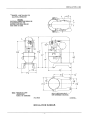
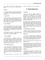
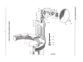
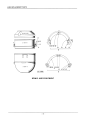
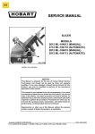
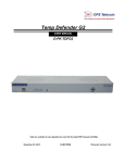
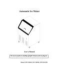
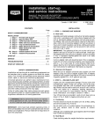
INSTALLATION L-800
*DENOTES 1-1116" DIA. HOLE FOR
ELECTRICAL CONNECTION
WARNING
ELECTRICAL CONNECTIONS SHOULD BE
IN ACCORDANCE WITH THE - - - NATIONAL ELECTRICAL CODE OR
SUCH CODES .!!:! FORCE - - -
1"
484
7"
55 8
NOTE: -BOLTING TO FLOOR
=
DECK PLATES AVAILABLE
FOR PERMANENT MOUNTING
UNNECESSA~
EXCEPT ON SHIPBOARD
D-109122
IPL-114371
INSTALLATION DIAGRAM
- 3 -
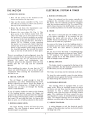
L-800 INSTRUCTIONS
2
3
4
5
6
IPl.:-123481
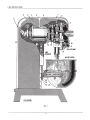
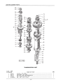
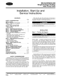
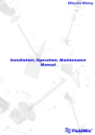
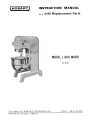
Fig. I
- 4-
7
INSTRUCTIONS L-800
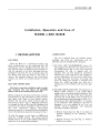
Installation, Operation and Care of
MODEL L-800 MIXER
I INSTALLATION
LUBRICATION:
The oil is drained from the machine before
shipping, and both the transmission and the
planetary must be refilled before operation.
LOCATION:
Place the Mixer in a convenient location, and
allow working space on the handwheel side. All
maintenance can be handled from this side, the
top, and the front. It should not be necessary to
bolt the machine to the floor, although holes are
provided in the base for use in special cases. Set
the Mixer level and use shims if the floor is
uneven. The machined edge on top of the transmission case makes an excellent surface for leveling.
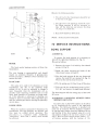
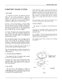
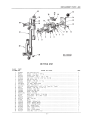
A. TO FILL THE TRANSMISSION remove the
front support for the top cover which serves as
the oil-fill plug (8, Fig. I). Use only the special
transmission oil that is shipped with the
machine. The oil level should be somewhere
between the center and top of the oil gage for
correct lubrication. If the oil level falls below
the gage line when the motor is running, add
more oil. While the machine is running, look
down the oil-fill and make sure that oil is
pouring out of the delivery tube onto the gear
face.
ELECTRIC CONNECTION:
Electrical connections should be made by qualified workmen who will observe all applicable
Safety Codes & the National Electrical Code.
B. FILLING THE PLANETARY: The planetary of
Model L-800 contains a gear pump which
supplies oil to the internal gear and pinion. This
oiling system is the key to the quiet operation
and long life of the Mixer. The oil capacity in
the recommended operating range is from 5 to 7
fluid ounces. Since approximately I oz. remains
in the planetary after draining at the time of
shipping, 6 oz. are shipped in an 8 oz. can
labeled "Oil For Planetary". The following
procedure should be observed:
Before making the electrical connections, read the
specifications on the name plate to make sure that
they agree with those of your electric service.
Remove the top cover, which is held in place by
two screws (3 and 7, Fig. I). Bring the power line
in through the hole at the top of the pedestal, and
connect to the motor controller (I, Fig. I). This is
the only connection required. Three-phase
machines must be so connected that the planetary
runs in the direction shown by the arrow in Fig. I.
I. Remove drain plug ( 12, Fig. I) to check on
previous draining of the planetary. Then
replace.
To start the motor, set the timer on HOLD and
push the START button. The speed selector
handle must be at one of the numbers indicating a
speed, not at an intermediate position.
2. Remove the drip cup (10, Fig. I), which is
held by two screws.
- 5 -
l-800 INSTRUCTIONS
3
4
I PL-114391
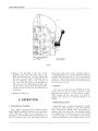
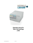
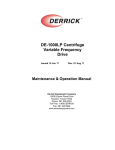
Fig. 2
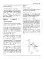
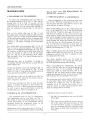
3. Remove the fill plug in the rim of the
planetary and insert the elbow that is supplied with the machine. Turn the elbow with
the open end up so that it will guide the oil
into the planetary. Pour in the contents of
the 8 oz. can and after a few moments to
allow the oil to be distributed properly, take
out the elbow and screw the fill plug in tight.
A little excess oil will run out while this is
being done.
and for the timer to be set for a definite time (or
on HOLD) before the machine will start and keep
running. With the timer set at "0" the start button
becomes a "jog" button and permits inching of the
planetary. As soon as the button is released, power
to the motor is cut off.
2. BRAKE:
The brake is actuated by the STOP button. This
button has two sets of contacts ; when it is first
depressed the power is cut off from the motor.
When pushed all the way down, the brake is
applied and remains on until the button is released.
4. Replace the drip cup.
II OPERATION
3. SPEED SELECTION:
Speed selection is made by lining up the handle
( 4, Fig. 2) with numbers on the shift selector
plate. Moving the handle from one station to
another does not shift gears, but instead changes
the engagement of clutches. A cam (7, Fig. 2) and
a switch ( 6, Fig. 2) are provided to turn off the
motor automatically as the handle starts to move.
1. ELECTRICAL SYSTEM:
The L-800 is equipped with a solenoid starter
with thermal overload protection and automatic
re-set. The pilot circuit is so wired that it is
necessary for the handle of the speed selector ( 4,
Fig. 2) to point to one of the four speeds indicated
- 6 -
INSTRUCTIONS L-800
Use the brake, or simply pause until the agitator
stops, and the speed can be changed without
effort.
machine, on either side of the motor controller.
Ill MAINTENANCE
4. BOWLS:
The regular bowl for this mixer has a capacity
of 80 quarts. By using an adapter and agitator to
suit, bowls of 60, 40 or 30 quart capacity can be
substituted.
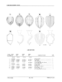
5. AGITATORS:
When putting on an agitator, the bowl must be
in the down position. Slip the agitator up on the
shaft and turn it around until the driving pin in the
shaft reaches the end of the L-shaped slot in the
shank. Agitators of various styles are available,
each suited to a particular job.
6. ATTACHMENTS:
Various attachments and accessories are available for this machine, such as; Dicer, Vegetable
Slicer and Shredder, Food Chopper, Soup Strainer
and Colander, Oil Dropper, Tray Support, Bowl
Jacket, Bowl Truck, Bowl Splash Cover and Bowl
Extension Ring.
The attachment socket is of the No. 22 size and
four speeds are available, corresponding to the
settings of the speed selector handle.
7. MEAT CHOPPER:
The L-800 Mixer is designed to drive the
chopper attachment in third speed. Should bone
chips or other materials clog the cylinder and stall
the machine, turn off the mixer at once, take off
the chopper handwheel, and remove the obstruction. Never start a stalled machine in any
speed until this has been done.
8. OVERLOAD RELEASE:
The starting switch is equipped with an automatic re-set. When an overload causes the switch
to throw out and thus stop the motor, it is only
necessary to wait a minute until the thermal
element cools, and then press the START button
again. The conditions that have caused the overload should of course, be remedied before starting
again.
The thermal elements are at the back of the
CLEANING:
This mixer meets the "BISSC" sanitation requirements. A kit which includes a brush and a
bowl scraper is furnished to aid in cleaning
operations. The bowl scraper, with a cloth wrapped
around it, provides a cleaning tool to reach the
narrow opening between the bowl yoke and
pedestal at the slide way. Other areas may be
cleaned by using the brush.
The mixer should be cleaned daily; the exterior of
the machine, bowls, agitators and accessories. The
special base allows ample room to clean under the
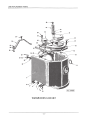
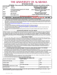
mixer. The bowl support apron (9, Fig. 3) has slots
which permit easy removal by loosening the
thumb screws. Behind this apron is an access
cover (2, Fig. 3) which may be removed for
cleaning.
AGITATOR SHAFf BEARINGS:
Agitator shaft bearings are sealed and ordinarily
require no attention. A Hobart service technician
may remove the seals if greasing becomes necessary.
BOWL LIFT:
A small can of graphite grease is shipped with
the mixer to be used on the lift screw and gearing.
They should be greased annually. The lift screw
can be reached by removing the apron, which has
screw slots and is held in place by four screws.
Rub a little graphite grease on the slideways while
the apron is off.
The gearing is located on the handwheel bracket
inside the pedestal. Remove the top cover (6, Fig.
1) and wipe some grease on the gear teeth. Protect
yourself from the electrical supply at the starter.
The handwheel shaft may be oiled through an oiler
on the handwheel bracket.
DRIP CUP:
Should moisture condense in the planetary, due
to atmospheric conditions, or the type of work
being done, the drip cup will prevent it from
reaching the bowl. Take the cup off occasionally
and wipe it out.
- 7-
L-800 INSTRUCTIONS
Observe the following routine :
I. The oil level in the transmission should be up
to the line in the gage .
2. The oil level in the planetary should be up to
the filling opening. It will be necessary to
take off the drip cup and remove the plug
(I I, Fig. I) to check this.
3. Keep bowl slideways lubricated .
NOTE: Avoid excessive lubrication .
IV SERVICE INSTRUCTIONS
BOWL SUPPORT
A. REMOVAL:
To remove the bowl support, it is necessary to
take off the right-hand slideway (G, Fig. 3).
Proceed as follows:
Fig. 3
MOTOR :
I . Remove the apron. It is held by four thumb
screws (I, Fig. 3).
The front motor bearing receives oil from the
transmission.
2. Break the paint covering the heads of the
three lower screws A, Band C.
The rear bearing is grease-packed and should
require no attention. However, if greasing does
become necessary, a Hobart service technician can
remove the seals.
3. Run the bowl support all the way down and
remove the bowl lift nut retainer (4, Fig. 3 ).
Then run the nut back up the screw.
PLANETARY:
4 . Pry the spring seat (3, Fig. 3) up off the pins.
The same oil is used in the planetary as in the
transmission, but due to the relatively small
volume of oil, it may be advisable to change it
more frequently than the transmission oil, especially under steaming conditions such as exist
when large quantities of potatoes are being mashed. If the planetary is removed for cleaning, care
should be taken to mesh the fiber pump-drive gear
with the internal gear before shoving the planetary
up into place.
5. Take out the six socket-head screws A, B, C,
D, E & F and remove the right-hand slideway .
The bowl support will then swing clear of the bowl
lift screw.
B. REMOVING LOOSENESS BETWEEN BOWL
SUPPORT AND WAYS:
Excessive play in the bowl support can be taken
up by loosening all the screws in the right-hand
slideway. The left-hand slideway is doweled and
need not be removed. Pull the slideways together
by placing large clamps across the slideways at top
and bottom of the bowl support when it is in its
top position. Tighten the top four screws F, E, D
and C. Run the bowl support down within 1-1 / 2"
of bottom position , pull the bottom of the
LUBRICATION:
When the machine is prepared for shipment, the
transmission case and planetary are drained , and
they must be refilled before operation. This
procedure is explained under installation
"lubrication". After that , a weekly check should
be sufficient .
- 8 -
INSTRUCTIONS L-800
slideway in with a clamp, and tighten the two
lowest screws B and A.
BRAKE
BRAKING ACTION:
C. ADJUSTING BEATER CLEARANCE:
Adjustment should always be made with the
bowl and type B beater in place. Remove the
"caplug" cover ( 17, Fig. l) and loosen the bumper
stop (16, Fig. I). Next loosen the lock nut (15,
Fig. 1) and turn the screw (18, Fig. 1). Be sure to
re-tighten the lock nut and the bumper stop and
re-assemble the "caplug" after the proper adjustment has been obtained.
BOWL LIFT MECHANISM
A. BOWL LIFT SCREW:
Replacement of the bowl lift screw necessitates
removal of the motor (see service instructions
"motor") and the bowl support (see service
instructions "bowl support").
End play adjustment in the bowl lift screw (5, Fig.
3) is provided by the lock nut (8, Fig. 3). Upward
thrust on the lift screw is taken by a shoulder (6,
Fig. 3) which bears against the transmission case;
downward thrust is taken by the permanentlysealed ball bearing (7, Fig. 3). A minimum of
.005" end play should be allowed.
In 4th speed, the brake ( 19, Fig. l) should stop
the planetary in about one revolution.
TO INCREASE BRAKING ACTION:
If the machine does not stop quick enough,
hook the brake spring in the next hole in the brake
band. Some solenoids have slotted feet and may be
raised slightly to increase the spring tension.
TO REDUCE BRAKING ACTION:
If the braking action is too severe, make sure
that the solenoid is in its lowest possible position
(if adjustable) and that the spring is in the top hole
in the brake band. Pull the solenoid core up by
hand until the brake band just touches the drum.
With no tension on the spring, the remaining travel
of the solenoid core should not exceed 5/16". If
the possible travel exceeds this amount, stretch the
spring by holding the solenoid closed and pushing
down on the brake band. Do this carefully, for it
can easily be overdone.
If the solenoid travel is less than 5 /16", it will be
necessary to reduce the contacting length of the
brake band on the drum. Grind down or file the
lining near the pivot end until it is clear of the
drum.
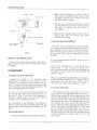
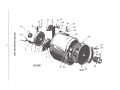
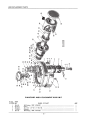
B. HANDWHEEL BRACKET:
This bracket (7, Fig. 4) carries a pair of miter
gears (3, Fig. 4) and the bowl-lift gear (5, Fig. 4).
It can be removed by taking off the handwheel,
thus exposing the four screws (2, Fig. 4) that hold
the clamping ring to the bracket.
The handwheel is secured to its shaft by a straight
Groov-Pin (1, Fig. 4) which can be driven out in
either direction. DO NOT POUND ON END OF
HAND WHEEL SHAFT. Pry the bracket free from
inside the pedestal, or drive the dowel pins
through the holes in the pedestal.
5
The Flexloc nut ( 4, Fig. 4) must be set with the
handwheel and bracket assembled to the pedestal
as in Fig. 4. Allow just enough end play in the
handwheel shaft to prevent the handwheel from
binding against the clamping ring. The miter gears
are held in proper relation by a spacer ( 6, Fig. 4)
placed between the bowl lift gear and the handwheel bracket bearing. A new spacer may be
necessary when replacing either of the gears or the
bearing.
HANUWHEEL~
IPL-114411
Fig. 4
- 9-
L-800 INSTRUCTIONS
INTER.J'\'AL
2. Take out the planetary oil seal (3, Fig. 5 ).
This seal can be pried out by using a small
screwdriver between the outside of the seal
and the planetary casting.
PINION
INTERNAL
GEAR
3. Pry out the oil-retaining cap (9, Fig. 5) which
is pressed into the top of the internal pinion.
(Be sure to replace this cap when reassembling).
SHAFT
4. Remove the retaining ring (8 , Fig. 5) and the
pinion, then drive the beater shaft down
through the bearings.
BEARING
C. BEATER SHAFT BEARINGS:
TWO HEADLESS
SET St:REWS
5
IPL-114421
The seals of these bearings are easily removable
for cleaning and repacking, should that be necessary . Bearing seals can be removed by inserting a
knife blade under the rubber seal where it touches
the outer race . They can be snapped back in place
by hand.
Fig. 5
REMOVAL OF BRAKE BAND:
If a new bearing must be installed, be sure to use a
sealed bearing.
Remove the cotter pin and washer at the pivot .
Slip the band off the pivot, and unhook it from
the spring.
If the lower bearing does not come out with the
beater shaft ( 6, Fig. 5) it can be pulled down
after the beater shaft is out. The upper bearing can
be pulled out after removal of the planetary oil
baffle (7, Fig. 5).
PLANETARY
A.REMOVALOF PLANETARY:
When re-assembling the oil baffle to the planetary ,
a little Permatex around the "0" ring (I I , Fig. 5)
will improve the seal. Be careful not to cut the
"0" ring on the edge of the planetary or baffle .
Support the weight of the planetary while
removing the retaining screw (2, Fig. 5). If the
removal of the planetary proves difficult , use the
two 3/ 8" tapped holes provided on opposite sides
of the planetary shaft for anchoring a puller. The
holes are plugged with nylon plugs.
D. PLANETARY SEAL:
The primary purpose of the seal (3, Fig. 5) is to
keep moisture and ingredients from the bowl out
of the lower bearing. It can be slipped down from
the top of the shaft and over the small shoulder (4 ,
Fig. 5) if care is taken . Grease the shoulder so that
the seal will slide over it. If installing the seal from
the bottom, you must remove the beater pin (5 ,
Fig. 5), clean the shaft, and make sure that the lip
of the seal is not cut or folded under. The lip must
go up toward the bearing. Make sure that the
spring is in place in the seal groove adjacent to the
lip. If the lip of the seal is dry, the seal may squeal.
A little lubrication worked under the lip will
correct this.
If a pry is to be used between the planetary and
the internal gear, always pry downward. The cast
iron lip (I, Fig. 5) on top of the planetary is
breakable. This lip serves as a trap for the oil and
would have to be repaired if broken .
On re-assembly of the planetary, care should be
taken to mesh the fiber pump-drive gear with the
internal gear before shoving the planetary up into
place.
B. BEATER SHAFT:
I. Remove the planetary as previously explained .
-
10 -
INSTRUCTIONS L-800
PLANETARY OILING SYSTEM
If the planetary is dry, 6 oz. of oil will bring the
level up to the overflow. Sufficient time must be
allowed to permit the oil to reach its own level.
Machines that have been drained will still have at
least 1 oz. left in them, and this must be taken
into account. If too much oil is put in, it will be
thrown out at high speed and collect in the drip
cup.
A. OIL PUMP:
To reach the oil pump, the planetary must be
taken off. See service instructions "planetary
removal". The oil pump should not require attention, but check to see if it is pumping by
turning the large fiber conveying gear counterclockwise as indicated by the arrow in Fig. 6.
The same grade of oil is used in the planetary as is
used in the transmission. See separate page.
If there is oil in the planetary, a stream should
flow out the end of the manifold (I, Fig. 6) and
D. OIL LEAKAGE:
fall back into the planetary. A little oil should also
come out of the small hole (2, Fig. 6) and drip on
the conveying gear. If no oil is delivered to the
gear, the hole (2, Fig. 6) may be clogged.
Oil leakage is controlled in the following manner:
The planetary oil shield ( 10, Fig. 5) keeps oil from
collecting on the hub and working down the
planetary shaft.
To remove the pump, take out the two screws ( 4
& 7, Fig. 6). Insert the screwdriver through the
hole (8, Fig. 6) to reach them. The other screws
should not be touched, unless it is necessary to
dis-assemble the pump.
The oil baffle (7, Fig. 5) keeps oil away from the
beater shaft as it is thrown off the pinion teeth or
sloshes around in the planetary.
The mechanism consists of two small gears which
float in the pump body (5, Fig. 6). Therefore, if
screws (3 & 6, Fig. 6) are distrubed, it will be
necessary to align the top plate assembly with the
pump body, so that the shaft and gears turn freely.
The friction plug (9, Fig. 5) stops any oil leakage
from above.
Screw 6 (Fig. 6) is larger than screw 3 (Fig. 6), so
that the pump cannot be assembled wrong.
1
The oil conveying gear is held to its shaft by a
rollpin in the hub. The pin may be driven out in
either direction.
B. PLANETARY OIL SHIELDS:
2
_....-c:r---·cONVEYING GEAR
MESHES WITH
INTERNAL GEAR
The shield ( 10, Fig. 5) is held in place around
the hub of the planetary by friction.
Its purpose is to keep oil from being flung off the
conveying gear and internal pinion onto the
planetary shaft at high speed. Be sure to replace it
if it is ever removed.
7
5
C. OIL LEVEL:
INLET
The oil level in the planetary is subject to
considerable variation. The oil-fill hole in the side
of the planetary is so located that it also serves as
an overflow, if the machine is level.
BASE
Fig. 6
-II -
IPL-114431
L-800 INSTRUCTIONS
TRANSMISSION
any of these parts. SEE REPLACEMENT OF
SHEAR KEY, paragraph H.
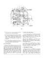
A. DIS-ASSEMBLY OF TRANSMISSION:
C. WORM GEAR SHAFT & ADJUSTMENTS:
To remove the transmission case cover take off
the bearing retainers (2 & 8, Fig. 7). Take off the
locking nuts (3 & 9, Fig. 7) and pry off the
transmission case cover. The top ball bearings will
come off with it. Lay the cover aside carefully so
that the oil-delivery tube (20, Fig. 2) will not be
bent.
Start dis-assembly of the worm gear shaft from
the bottom. When the locking nut (25, Fig. 7) is
off, the gears and other parts will be loose on the
shaft and may be taken off easily.
Pull out the shifter slide rod (2, Fig. 2) and
dis-engage upper and lower shifting yokes from the
clutches. This can usually be done without taking
off the shift selector plate (8, Fig. 2) and gear-shift
bracket (5, Fig. 2). Be sure that the power to the
machine is off before working on the gear-shift
bracket.
The clutch shaft and worm gear shaft (16 & 34,
Fig. 7) must be removed together. The worm gear
shaft has a self-aligning ball bearing (26, Fig. 7) at
the bottom, so that it can be tilted away from the
worm far enough to clear it. Lift off the upper
gear ( l I, Fig. 7) on the planetary shaft. Notice
that the shim (7, Fig. 7) on top of this gear has the
relieved side up.
Although this gear is reversible, it should be
re-installed with the same side up, so mark the top
when taking it off.
On the clutch shaft, remove the bearing (4, Fig. 7),
washer (5, Fig. 7), top pinion (6, Fig. 7), and
clutch (32, Fig. 7). Then work the clutch shaft and
worm gear shaft assemblies out together.
The planetary shaft can be pulled out after the
planetary has been removed. See service instructions "planetary removal".
If the lower bearing (23, Fig. 7) must be withdrawn , it will be necessary to first remove the
chimney (22, Fig. 7). When replacing the chimney,
be sure to get a good seal between it and the
transmission case, to prevent leakage of oil.
~hen
re-assembling, put on the retaining ring (33,
Ftg. 7), the spring (31, Fig. 7), the shock absorber
part (30, Fig. 7) and the worm gear (28, Fig. 7). It
will then be necessary to use a vise or press to get
these parts up where they belong. Press the worm
gear up far enough to permit insertion of the key
(27, Fig. 7). Release the vise pressure carefully and
avoid burring the worm gear because the bottom
o~ the hub acts as a thrust bearing. The key (27,
Ftg. 7) will hold the assembly in place until the
remaining parts can be threaded on and pulled up
tight by the locking nut (25, Fig. 7).
When a sudden load causes the worm gear to turn
slightly on its shaft, the cams (29, Fig. 7) move the
compressor element (30, Fig. 7) upward so that
the spring takes the shock.
The shock absorber action can be tested by
holding the shaft in a vise, turning the worm gear
by hand against the spring, and releasing.
When re-assembling the transmission, be careful
not to cock the outer race of the self-aligning ball
bearing (26, Fig. 7). It is possible to install the
worm gear shaft by itself and then raise it far
enough to get the clutch shaft in place without
pulling the bearing (26, Fig. 7) out of its seat. This
will avoid the risk of cocking the outer race.
The worm gear must mate properly with the worm
on the motor shaft, and a vertical adjustment is
provided by a sleeve (I, Fig. 7). The sleeve is
correctly set at the factory and locked by two
small set screws, so unless replacements have been
made no change will be necessary.
Adjustment may be made as follows:
B. REMOVALOF ATTACHMENT HUB:
I . See that the transmission case cover is bolted
down tight.
The attachment hub (19, Fig. 7) is fastened to
the transmission case by four bolts (18, Fig. 7).
The heads of these bolts being inside the case, a
partial dis-assembly of the transmission will be
necessary before the attachment socket or the
bevel pinion (21 , Fig. 7) can be removed.
2. Take out the two small set screws (one on
top of the other) that lock the sleeve (I, Fig.
7). Turn the sleeve (I, Fig. 7) a fraction of a
turn in a clockwise direction until the motor
shaft begins to bind when revolving the rotor
by hand.
Replacement of the square drive sleeve (20, Fig. 7)
however, can be accomplished without disturbing
- 12 -
7
6
8
TRANSMISSION
CASE COVER
27
IP1:12349l
Fig. 7
3. Turn the sleeve counter-clockwise until the
same thing occurs in the top position.
4. The total movement may be as much as half a
turn. Mark the halfway point. Set the sleeve
about midway between the halfway point
and the top position. This will bring the
worm gear on the high side of center, as it
should be.
5. Use a drill to spot the adjusting sleeve for the
set screw. A second set screw goes into the
same tapped hole to lock the first one.
D. CLUTCH SHAFT:
All gears in this assembly must be free to turn
on the shaft and the clutches should slide freely up
and down on the splines. If a clutch seems to bind,
take it off, turn it to a new position and try again.
The top and bottom gears must have a few
thousandths end play between the shaft shoulders
and the washers that are between them and the
ball bearings. The lower bearing (24, Fig. 7) on the
clutch shaft must be assembled to take the
downward thrust (thin section of outer bearing
race up).
- 13 -
E. THE PLANETARY SHAFT:
An "0" ring ( 14, Fig. 7) is set in the bevel gear
to prevent oil leakage down the planetary shaft.
When moving the bevel gear ( 17, Fig. 7) on the
shaft, be careful not to cut the "0" ring on the
keyway (13, Fig. 7) that is just above it.
The bevel gear adjustment is governed by the
thickness of the planetary-shaft shim (7, Fig. 7).
This shim must be installed with relieved side up
and the flat side down.
A new shim may be required if gear (11, Fig. 7),
gear ( 15, Fig. 7), spacer ( 12, Fig. 7), or top bearing
(1 0, Fig. 7) is replaced. A new bevel gear or pinion
should not require any change in shims.
F. THE SHIFTING YOKES:
Change of speed is accomplished by turning the
shift handle (4, Fig. 2) to one of the positions
numbered on the shift selector plate (8, Fig. 2).
Moving the handle turns the two cams (16 & 19,
Fig. 2) which in turn operate the shifting yokes (3
& 10, Fig. 2) that engage and disengage the
L-800 INSTRUCTIONS
clutches. The spring-loaded plungers ( 14, 15, 17 &
18, Fig. 2) give some flexibility to the shifting so
that the handle can be moved to a new position
even if a clutch does not engage immediately.
The travel of a plunger can be adjusted by
loosening a lock nut (13, Fig. 2) or taking
out a cotter pin (11, Fig. 2) and turning a
screw ( 12, Fig. 2). All of these screws should
be set so that the total movement of each
plunger is between 3/16" and 7 /32". This insures that when the handle is moved to a
different speed the clutch will not hang up in
the previous speed. A clutch cannot be disengaged if it is transmitting power, but after
the motor is shut off and the machine stops,
shifting becomes effortless.
G. SPEED CHANGE:
Removal of the shift selector plate (8, Fig. 2)
exposes the speed-changing mechanism. The plate
can be removed without disturbing the shift
handle. The precision switch (6, Fig. 2) is connected directly to the line, so cut off the power to
the entire machine before working around it. The
switch is operated by the cam (7, Fig. 2) so that
power to the motor is cut off automatically while
speeds are being changed.
The gear-shift bracket assembly (5, Fig. 2) can
be removed as a unit by taking out four
screws (9, Fig. 2). This bracket is easily removed and affords a handy inspection hole.
When replacing the bracket assembly, have the
shift handle in third speed because the shifting
yokes naturally take this position when the
cams are withdrawn. Tilt the shift cam assembly toward the front of the machine until
one side of the bracket is in contact with the
transmission case. Then square up the bracket
against its seat and insert the screws. It is
very important to have a good seal to the
transmission case. Paint the joint with Permatex or sealing compound.
1~
4
I PL-114451
3
Fig. 8
H. REPLACEMENT OF SHEAR KEY IN ATTACHMENT DRIVE:
The attachment drive is protected by a
brass key (I, Fig. 8) that will shear if the
load becomes excessive. To replace a sheared
key it is only necessary to remove the
square-drive sleeve (3, Fig. 8). The sleeve can
be taken out through the attachment socket.
The screw ( 4, Fig. 8) that holds the sleeve in
has a left-hand thread; turn it clockwise to
remove.
If the sleeve sticks and does not come out
easily, insert a standard 3/8"-16 screw into the
right-hand threads at (2, Fig. 8). The screw
should be long enough to reach out where it
can be grasped and used as a puller.
After taking out the pieces of the sheared key
check to see that the square-drive sleeve turns
freely inside the pinion shank before putting
in the new key.
The replacement key must be of brass.
I. OIL SYSTEM:
The oil level in the transmission case should
always be at, or slightly above, the line on
the gage. The transmission oiling system consists of a flinger ( 4, Fig. 1) pinned to the
motor shaft behind the worm, a guide (2, Fig.
1) to direct the oil and a tube (5, Fig. 1)
which delivers the oil to the gear (9, Fig. 1).
The discharge end of the oil tube is visible
through the oil-fill hole (21, Fig. 2). After
any service work has been done involving the
opening of the transmission case, check the
end of this tube to make certain that a full
stream of oil is striking the gear. If the oil
stream fails or is intermittent, the intake end
of the tube has been bent.
J. OIL:
The proper oil is shipped by the factory for use
in this mixer. Hobart servicing offices have the
current lubricants listed in their lubrication manual. It is a high quality, extreme-pressure gear oil
with oxidation and corrosion-inhibiting additives.
Its viscosity is 65 to 70 Saybolt universal seconds
at 210° F. If any other oil is substituted, it is
important to check the flow out of the oil delivery
tube. Any oil that is too heavy to circulate will not
do for this application. In general, the oil should
be as heavy as an SAE-30 motor oil, but no heavier
than a light, all purpose, automotive gear oil.
Always check oil flow through the delivery tube.
INSTRUCTIONS L-800
THE MOTOR
ELECTRICAL SYSTEM & TIMER
A. REMOVING MOTOR:
A. MOTOR CONTROLLER:
I. Shut off the power to the machine at the
source and remove the top cover.
2. Take out the motor controller (1, Fig. 1). It
will only be necessary to remove one screw at
the top of the controller base.
3. Drain the oil from the transmission case.
Remove the drain plug ( 13, Fig. I).
4. Remove the cover plate (14, Fig. I). This
gives access to the bottom motor bolt. The
other two bolts can be seen from the top of
the machine. If a hoist is available, an eyebolt
can be used in the hole provided for it on the
motor next to the junction box. The hole is
tapped 3/8"-16. Without a hoist, removing
the motor is a two-man job. After it has been
worked out of its seat, it can be rested on the
throat of the pedestal, which helps to protect
the bowl-lift gearing. Do not pull the motor
back so far that it falls down on these gears.
There is no problem of motor alignment, since the
motor is located by the face and bore of its seat in
the transmission case. An "0" ring serves as a seal
between the motor and transmission case.
Permatex spread on this diameter keeps oil from
getting past the "0" ring and the machined
grooves.
When installing the motor, be sure that the "0"
ring is wet with Permatex or oil, so that it will be
compressed when entering the transmission case
and not be cut.
When the solenoid on the motor controller is
energized, the controller circuit closes and starts
the motor, but the solenoid cannot be energized
until the precision switch (6, Fig. 2) is closed. This
switch closes whenever the shift handle is in one of
the numbered positions on the shift selector plate.
B. TIMER:
The timer is connected into the holding circuit
of the motor controller. If its contacts are not
closed, the motor will run only as long as the
START button is held down. In this case, the start
button can be used as a jog button.
As soon as the timer is set, the holding circuit is
completed and the motor will start and continue
to run when the start button is pressed and
released.
Do not try to force the timer. A mechanical stop
inside the timer prevents a short-cut from "Hold"
to "0" position. If it doesn't turn clockwise, it
might actually be on the hold position and only
look as though it were on zero.
C. BRAKE CIRCUIT:
The brake circuit is connected to the line at the
motor controller, but the brake is operated by the
STOP button, not by the controller.
The brake circuit has one live terminal at all times.
To stop the mixer quickly, press the stop button
and hold it down against the bottom contacts until
the brake brings the machine to rest.
B. THE OIL FLINGER:
The oil flinger is small enough to clear the
transmission case when withdrawing the motor.
Before replacing the motor, check the flinger to
see that it is running true. A flinger that is not
running true can force oil through the bearing,
which is objectionable.
D. OVERLOAD RELEASE:
of the bearing bracket, remove the flinger and
examine the oil-return hole just below the bearing.
If the bearing contains grease, there is a possibility
that some if it may plug this hole. As long as this
drain is open, no oil will accumulate in the motor.
The starting switch is equipped with an automatic re-set. When an overload causes the switch
to throw out and thus stop the motor, it is only
necessary to wait a minute until the thermal
element cools, and then press the START button
again. The conditions that have caused the overload should of course, be remedied before starting
again. The thermal elements are at the back of the
machine, on either side of the motor controller.
C. MOTOR LUBRICATION:
E. WIRING DIAGRAM:
The front bearing receives oil from the transmission. The rear bearing is grease packed and
should require no attention.
A wiring diagram to suit the electrical specifications of the particular machine is attached inside
the large top cover.
If any oil appears inside the motor at the bottom
- 15 -
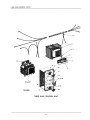
L-800 REPLACEMENT PARTS
22
IPL-135281
TIMER AND CONTROL UNIT
- 16-
REPLACEMENT PARTS L-800
TIMER AND CONTROL UNIT
PART
ILL US.
PL-13528 NO.
1
*2
*3
*4
*5
*6
*7
*8
*9
10
11
12
13
14
15
16
17
18
19
20
21
22
23
*24
25
*26
27
28
E-117271
C-102536
A-102728
SC-8-9
WL-3-20
FE-14-19
SC-13-11
M-83392
M-85432
M-69918
A-102228
SD-15-15
A-102467-1
SC-13-7
A-103228
A-103229
B-73540
SC-15-26
WS-2-18
A-102467-2
A-102229
C-117853
P-87712-25-1
P-8 7712-25-3
P-87712-21-1
P-87712-21-2
**
SC-7-37
NAME OF PART
AMT .
Harness - Wiring
------------------ - ------ -- - - - - --- - - - --- - - -Harness -Wiring
- - -- - ------ -- - -- -------- -- --------- -- ----- -Transformer (440/ 380 V. to 115 V.) -- -- -- - --- - -- - -- - --------------Mach. Screw - #10-24 x 3/8" Rd . Hd. -- --- - ----- - ------- -- - - - - --- - Lock Washer - #10 x .055 " x .040 " --- -- - --- - - --- - - ---------------Fuse (1 .5 Amp.) ----- - --- -- - - - -- ----- ----- - - ----- - ---------Mach. Screw - #6-32 x 1/4" Flat Hd.
-------- ----- - ----- -- - --- - ---Fue B~ck -------- - -------- ---- --- -- - ----- - - ---- ---- -- -- - Insulator - Fuse
----------------------- - - - - - -- - ------ ------ Insulator -Push Button Station
------------- - ------------ - ------ Push Button Station Sub-Assy. ------ - --- - - -- ---------------- ---- - -Self-Tapping Screw - # 8-32 x 3/8" Truss Hd. "Taptite" --- - - - - --- ------- - - Cap - Push Button (Start) --- -- --- --- -- ---- - - ------- - - - - -- -- --- Mach. Screw - #5-40 x 1/4" Flat Hd.
---------- - -------- --- -- - ---- Timer & Gasket Assy. (15 Min.) - -- --------- --- -------- - ------- - - Timer, Dial & Gasket Assy. (30 Min.) (!nels. item #17) --------------- - ---Dial- Timer (30 Min. Timer) - - - ----- - -------- - --------- -- - - - - --- Mach. Screw - #8-32 x 5/ 16 " Oval Hd . - -------- - - - -----------------Washer
--- ---- - - - ---- ------ -- - - ------------------------ - - Cap - Push Button (Stop) ------------------------------ - ---- -- Push Button Station Sub-Assy. -- - --- -- - - ----------------- - - - -·-- -- Plate -Timer (15 Min .) ---- -- --------- - ---------- - --------- - --Starter Magnetic (208-230 V., 60H z. ; 220 V. , 50 Hz.) (1 Ph.) (Less Elements) -- - - - -- Starter - Magnetic (115 V., 50 /60Hz., 1 Ph.) (Less Elements) -----------------Starter - Magnetic (208 -220 V., 50 /60Hz., 3 Ph.) (Less Element s) ------ -- ---- - --Starter - Magnetic (115 V. , 50 /60Hz., 3 Ph.) (Less Elements) - ----- - - --- - --- - - Heater Element - Magnetic Starter (Give Elec. Spec. & Mach. Model) -------------- As
Mach. Screw - #8-32 x 1/4" Rd. Hd .
----------- - -- - ---- - ------ - --*115 V. Pilot Circuit.
**Hobart service technician to use Starter Element Part No. as listed on Starter Parts Sheet.
- 17 -
1
4
4
I
I
I
1
I
1
4
I
2
I
1
1
4
4
I
I
1
1
1
1
1
Reqd.
1
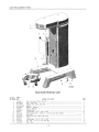
L-800 REPLACEMENT PARTS
1 --~ ·
2 ---~~~iiifii"
10
BASE AND PEDESTAL UNIT
ILLUS.
PART
PL-12350 NO.
I
2
3
4
5
6
7
8
9
10
11
12
13
14
15
S-24801-1
M-24781-1
B-117447-1
D-11800-143
R-24189-3
S-24260
P-70641-9
WL-4-2
SD-15-12
E-110222
R-21922-1
P-87669
WL-4-11
SC-62-83
A-116395
NAME OF PART
AMT .
Top Cover Assy. (!nels. item #2) ---------------------------------1
1
Seat - Top Cover - --- --- - ---------- - - - - ----------------- ----Pedestal Assy. (!nels. item #4) -----------------------------------1
Dowel- - - ------------ - - ------- --- - - ------ - -- --- - ---- --- - -2
Slideway - Pedestal - ---------- ------- ---- - --------------------2
Apron - Pedestal -------------------------------------------1
4
Thumb Screw ---------------------------------------------Lock Washer- 3/8" x .136" x .070" - ------- -- -- -------------- - -- --- 12
Self-Tapping Screw - 3/8"-16 x 1-1/2" Soc. Fil. Hd. "Taptite" -- --- - - -------- - 12
Base Assy. - ------ ----------- ----- ------ -- -- - ------ - --- - - - 1
Bowl Truck Assy. (!nels. item #12)
- - - -------- - -- - -------------- --1
Caster ----- -- --------- -------- - --------- - - - - - --- - --------4
Lock Washer- 1/2" x .171" x .125" ------------ -- ----------- ---- --4
Fin. Bolt- 1/2"-13 x 1-1/2" Hex Hd. -- - --- ------ - -- - - ----- - --------4
4
P~g-Ba~ ------------------------------------------------ 18 -
REPLACEMENT PARTS L-800
19
26
18
17
16
20~
12
10
27
5
11
8
28
IPL-135291
SHIFTING UNIT
ILLUS.
PART
PL-13529 NO.
I
2
3
4
5
6
7
8
9
10
11
12
13
14
15
16
17
18
19
20
21
22
23
24
25
26
27
28
29
P-24249
RP-2-5
P-60359
WL-3-44
SC-40-14
M-60394
RP-2-10
M-60400
D-67500-6
C-117873-1
SD-15-15
RP-2-3
M-60395
M-60469
M-60468
P-87711-71-1
SC-9-45
WL-3-7
M-60679
BA-2-18
V-7009
M-24230
M-24233
M-60723
M-24232
R-24229
M-24227
R-24228
PC-3-24
NAME OF PART
Gear Shift Cam Assy. ---- - - - - - - - - - ------·-- -- - - - - - - - - - - - - - - - - - - - Rollpin - 1/4 " Dia. x 7/ 8" Lg. -- -- - ------ ---- -- ---- - - - - - - -- - - - - - - - - Bracket - Gear Shift - - - - - - - - - - - - - - - - - - - - --- - --- --- - - - - - - - --- ---Lo ck Washer - 5/16" x .125" x .078"
-- - - - - - - - --- -- ------ --- - -- - - - - Cap Screw - 5/ 16"-18 x 3/4" Soc. Fil. Hd. - - - - - - - - - - -- -- - - - - - - - - -----Hub & Ca m Ascy. - - - - - - - - - - - - - - - - - - - - - - - - - - - - - - - - - - - - - - - - - - -Ro llpin - 3/ 16 " Dia. x 1" Lg. -- - - - - - - - - - - - - - - - - -- -- --- - - - - - - - - - -Shaft - Gear Shift - - - - - - - - - - - - - - - - - - - - - ------------ -- --- - - - ---" 0 " Ring - Shifter Shaft
- --- - - - - - - - - - - - - - - - - - - -- -- - ------ - - - - - Plate - Shift Selector - - - - - - - - - - - - - - - - - ------- -- -- - -- - -- -- -- - -- - - -Self-Tapping Screw - # 8-32 x 3/ 8" Tru ss Hd. " Taptite" - - - - - - - - - - - - - - - - - - -Rollpin - 3/ 16 " Dia. x 1-1 /4 " Lg. --- - - - - --------- - - - - - - - - - - - - - - - - - - Grommet -Gear Shift
- - - - - - - - - - - - - - - - - - - - - - - - - - - - - - - - -- - - -- -- Handl e and Hub Assy.
----------- - - ------ --- - - - ---- --------- - Knob -Gear Shift - - - - - - - - - - - - - - - - - - - - - - - - - - - - - - - - - - - - - - - - - -- - Switch - Interlock ------ - - - - -------------- - -------- - - - - - - - - - - - - - - - - Mach. Screw - #6-32 x 1" Rd. Hd. - - - - - - - - - - - - - - - - - - - - - - -- -- - - - - - Lock Washer - #6 x .040 " x .025" - - - - - - - - - - - - - - - - - - - - - - - -- - - - - - - - Insulat or -- - - - - - - - --- - - - -·-- --- - - - -- - - - - - - - - - - - - - - - - -- - -- --Ball - 3/8" Dia .
-- - --- - --·-- -- ---- - - - - - - - - - ---- - - - - - - - - - --- - -- Spring
- - - -------- - - --- - - - - --- - - - - - - - - - - - - - - - --- - - - - - - - - --Plunger - Shifting Yo ke --- - - - - - - - - - -- -- - - - - - - - - - - - - - - - - --- - - - - Spring - Shifting Plunger - -- - - - - - ------------ - - - - - - - --- - - - - - - - - - -Screw - Shifting Plunger ----- --- - --- - - -- -- - - - - - - - - - - - - - - -- -- - - - - - Nut - Plunger Screw ---- - - - - - - - -- - - - - - - - - - - - - - - - - - - - -- - - - - - -- - Yoke - Upper Shifting
--- -- - - - - - - - - - - - - - - - - - - - - - - -- - - - - - - -- -- Shaft - Shifter -- -- --- --- - - - - - - - - - - - - - - - - - - - - - - - - - - - - - - - - - - - Yoke - Lower Shifting
--- - - - - - - - - - - - - --- - - - - - - - - - - - ----- - - - ----Cott er Pin - 1/16" x 1-1 / 2" ----- --- - - - - - - - - - - -- - - - - - - - - - - --- ------ 19 -
AMT.
I
I
4
4
1
I
J
I
I
4
l
1
1
1
1
2
2
I
2
2
4
4
4
3
15
17
16
22
23
11
25
3
0
....
10
0
;liD
l>
z
~I
9
"'
,_,
lr#JBI ZJJ.I
c
flY//
;'"'•W4@f~g; /~
. . . . 27
28
"1'illl??h
~
, · ·~:~"''"
R ~
~ .
'
Cl:ll
;liD
l>
29
w'
~
m
c
z
....
IPL-1235U
33
REPLACEMENT PARTS L-800
MOTOR AND BRAKE UNIT
PART
ILL US.
PL-12351 NO.
I
2
3
4
5
6
7
8
9
10
11
12
13
14
15
16
**17
18
19
20
21
22
23
24
25
26
27
28
29
30
*31
*32
33
34
*35
36
37
P-24 771
NS-32-7
WL-3-43
SC-36-28
KW-3-5
R-60777
P-24776
M-24774
PC-3-32
WS-3-20
V-6566
M-24775
M-63201
PC-3-23
SC-7-41
P-23926-1
P-23926-7
M-24167-1
WL-7-6
NS-9-12
FE-2-33
SC-7-67
WL-3-15
M-78752-6
M-24726-1
D-67500-24
WL-3-43
SC-36-27
P-24610
RP-2-6
M-24298
RP-2-4
P-24257-1
P-24257-2
WL-4-12
SC-36-98
**R-24770-1
R-24770-2
NAME OF PART
Brake Mounting Bracket Assy. ---------- -- -- - - --- - ---- -- - - -- - - - - - - -· Stop Nut- 1/4"-20 "Flexloc" - - -- - -------- - - - - - - - - - - - - - -- - - - - - - - Lock Washer- 5/ 16" x .117" x .056" - - --- - --------------------- - - --Fin . Bolt- 5/ 16"-18 x 1-1 /4" Hex Hd.
---- - --- - -- - --------- - ------ -Key·- #405 Woodruff ------------- - -------------- - - - - ------ - --Drum- Motor Brake -- -- ------------ - -- - - - ------- - - - -- - - - - - - -- Brake Band Assy . - - - - --------------- - ---- - - - - - ----- -- - - ---- --Stud - Brake Band -- ------ - ------------- - --------------- - --- - Cotter Pin- 3/ 32" x 1/ 2"
------ - - - ----- - - - -------- - - -- - - - -- - - - Wuh~
-- -- --------------------- - ------------------ - --- - -
Nut-Lock --- - ---------- ---- -- - ------ - ----- - -------- - - - --Spring- Motor Brake - ------ -- ---- - ------------ - -------------- Pin- Solenoid Clevis - ---- --- -- -- -------------------------- - - - Cotter Pin- 1/ 16" x 1/ 2"
--------- - ---------------- - - - - --- - - - - Mach . Screw - #8-32 x 3/ 8" Rd . Hd . ------ - ----------------- - --- - - - Solenoid - Brake (208-240 V. , 50/60 Hz.)
---- - ----------- - ---- - -----Solenoid - Brake (115 V. , 50/ 60Hz.) -- -- ------------------- - - -- - -- - Clamp - Lead Support
--- - ----- - - - - - - - -- -- ------------- - --- - -Lock Washer- # 8 Ext. Shakeproof
-- - -------- - ----- - - - ---- - - -- - - - Mach. Nut- #8-32 Hex ---------------- - ----------- - - - - - --- - - - Connector - Straight (3 /4" Male Thd. x 3/4" Flex. Cnd .) - - - ----- - - - -- - - -- --Mach. Screw- # 8-32 x 5/ 16" Rd . Hd.
----- - ------- - - - ------- - - -- - - - - --- -- -- -- -------------------- Lock Washer- #8 x .047" x .031"
C~mp
----- -- - ---- - - - --- - ---- - ------- - - - --- - --- -- - - --- - Cover - Motor Junction Box -- -- - - - -- --- - -------------- - ---- - - - - - Motor (see separate Motor Parts Sheet)
- ---- - ---- - ---- - - - - - --- - ---- - "0" Ring - Bearing Bracket -- -- - - --------------- - ----- - -- - --- - - - Lock Washer - 5/16" x .117" x .056" ---------- - -------- - - - -- - ---- - -Fin. Bolt - 5/16"-18 x 1" Hex Hd. --- ------ - - - ----- - --- - ---- - - - ----Guide -Oil Flinger
- - ------- - - - - - ---- - -- - - - ----------- - -----Rollpin- 1/4" Dia. x 1" Lg. - --- - ----- - - - - --- - - --- - --------- - --- - Worm - Drive (5T) -- - ------ - - - -------- -- ----- - --- - - - -------- - Rollpin - 3/16" Dia . x 1-5 /8" Lg . --- - ----- - ------------- - ---------Flinger and Hub Assy . (60 Hz.) - - --- - - - --- - -- - ---- - -- -- ----- - --- - -Flinger and Hub Assy .
----- - ----- - ------ - - - - -- -------- - - - ----Lock Washer- 1/2" x .170" x .099" - ---------------- - - -- --- - ------Fin . Bolt - 1/ 2"-13 x 1-1 /4" Hex Hd. - - ----- -- --- - -- - -- - - - -- - -------Motor Brake Assy. (115 V., 50/ 60Hz.) (!nels. items #1, 2, 7, 8, 9 , 10, 12, 13, 14, 15,
17 , 18 , 19 & 20) - - --------- - ------------ - - - - - ---- - ---------Motor Brake Assy. (208-240 V., 50/60 Hz.) (!nels. items #1 , 2, 7, 8, 9, 10, 12, 13, 14,
15, 16, 18, 19 & 20) ---------- - -- --- ----- - -- - --- - - - ---- - ---- - *50 Hz. ONLY .
** 115 V. Pilot Circuit.
- 21 -
AMT.
I
I
4
4
I
I
I
I
I
I
2
I
I
I
4
I
I
I
4
4
I
4
4
I
I
I
I
2
2
I
I
I
I
I
1
3
3
L-800 REPLACEMENT PARTS
20
23
22
39---f
16
15
35--£
~11
34
I PL-11450 I
TRANSMISSION CASE UNIT
- 22-
REPLACEMENT PARTS L-800
TRANSMISSION CASE UNIT
ILLUS.
PART
PL-11450 NO.
I
2
3
4
5
6
7
8
9
10
II
12
13
14
IS
16
17
18
19
20
21
22
23
24
25
26
27
28
29
30
31
32
33
34
35
36
37
38
39
T-103196
WL-4-13
WL-4-14
SC-40-36
WS-21-21
SC-62-60
M-24665
M-24264-l
WL-3-15
SC-68-14
M-22793
D-11800-2 24
V-24670
T-24203
WL-4-2
SC-62-48
P-24255
WL-3-44
SC-36-28
SC-15-70
M-24782
P-24256
SC-38-5
WL-3-37
P-24254
SC-47-70
P-2425 3
SC-7-82
NS-32-1
D-11800-221
SC-62-66
SC-62-67
WL-4-13
M-68288
SC-36-4
WL-3-37
NS-13-1
P-62!08
SC-15-76
NAME OF PART
AMT.
Case - Transmission
------- ------ - - - --------- --- --------- -- -- 1
Lock Washer- 1/2" x .171" x .125" ---- --- - - ------ - ----- - --- - --- --I
I
Lock Washer- 1/2" x .109" x .172" -------------------------------Cap Screw- 1/ 2"-13 x 1-3/4" Soc. Fil. Hd. ----------- - - - - --------- - -- 2
Washer
-------------------- -- --------- - ---- - ------------1
I
Fin. Bolt- 1/2"-20 x J'' Hex Hd. ---------------------------------Gasket - Transmission Case Cover Plate
-- ----------- - - --- - - - - --- - - --I
Plate- Transmission Case Cover -----------------------------------I
Lock Washer- #8 x .047" x .031"
-- - --- - - - - - - - - ---- ------- - -----4
Mach. Screw - #8-32 x 3/8" Trimmed Hex Hd. - - - - ----- - -- ------ - - - -- - -4
I
Gage - Oil Level
- ---------------------------- - - ----- - - - ----Dowel
-------------------------------------------------2
Insulator - Fiber
--- - - ------------- - ----------- - --- - -------- 1
Cover - Transmission Case
---------- -- - - ---- ---- ------------ - - -1
Lock Washer - 3/8" x .136" x .070" -- ---- --- - - ---------- - -- ---- ---- 11
Fin. Bolt - 3/8"-16 x 1-1/8" Hex Hd. -- - -- --------- - - - - - ----- --- - ---- II
Retainer - Planetary Bearing ----- - - - --- --- - - - ----- -- -- --------- --1
4
Lock Washer - 5/16" x .125" x .078" ---- -- ---- - -------- - ------- --- -Fin. Bolt - 5/16"-18 x 1-1/4" Hex Hd.
-----------------------------4
1
Mach . Screw- 1/4"-20 x I" Oval Hd . - - - -- ------ -- - - - -- --- -- - ---- -- -Support - Top Cover Front ------------------- - ------ - - - ---- -- - -I
Retainer - Upper Worm Shaft Bearing ------ - - -- ------------- --- - ----1
4
Cap Screw- 1/4"-20 x !" Fil. Hd . -- ------ --- ------------------ -- -- Lock Washer - 1/4" x .109" x .062" ---- ------------- ------- - --- - --4
I
Sleeve - Worm Gear Adjusting ---- ---- -- ----- -- - -- - - - ----- --- ----Set Screw - #10-32 x 3/8" Soc. Hdls.,Cup Pt. ----- -- - ---- ----- - - -- ----2
Oil Delivery Tube & Plate Assy.
------ - -- ------- - -------- ---- -- - -1
--- ----- - ---------- - - - - - - - - --2
Mach . Screw- #10-24 x 3/4" Rd . Hd.
Stop Nut- #10-24 "Fiexloc" -------- ------ --- --- --- --- ---- ---- - 2
Dowel
---- ---------- --- - -- - - ----- - ----- - ----- --- ----- --2
2
Fin. Bolt- 1/2"-13 x 1-3/4" Hex Hd. -------- --- -- --- - ----- - - - - -- -- -Fin . Bolt- 1/2"-13 x 2-1/4" Hex Hd. -------------------------------2
4
Lock Washer- 1/2" x .171" x .125" ------- --- --- --- - --- - ---------- Shim (.0179" Thk.)
------------------ --- ----- - - ---- --- --- ---- As Reqd .
Fin . Bolt - 1/ 4"-20 x 3/4" Hex Hd.
-------------- - -- -- ----- -- - --- -2
2
Lock Washer- 1/4" x .109" x .062" ------- - -------- -- --- - - --- - ----Full Nut- 1/4"-20 Hex Fin. -------------------------------------2
Strap- Top Anchoring
--- - ----------------- -- -- - - - - --- -- -----I
Mach. Screw- 1/4"-20 x 1-3/4" Oval Hd. -- -- ---- -- ----- - - - -- ---- - ----I
- 23 -
rOo
0
0
:0
m
"'tl
r-
l>
48
(")
m
s:m
2
-1
"'tl
l>
:0
-1
(/)
0'
0
32
~
,...
Vt
c:
""G
""G
0
~I
....
"')>
z
c
,...
.,
....
c:
z
....
~-~
~~--lW#<~J_-. I~
~
~~~
_li\\.._~!!:\1!&1:'1
I~~:
-"' .·~-,~~
. ' ~>'*c'
.~\¥fj~
_,,...,~<'-';>.'«fff!/'-·""'- '~~
'·/.~ · -·%··~-
H
L
.
f·
·'
~~~I
16
-15
t1·
fi·
.
~
-14
13
t!j'----11
~--
10
IPL-12352]
REPLACEMENT PARTS L-800
BOWL SUPPORT AND LIFT UNIT
ILLUS .
PART
PL-12352 NO .
I
2
3
4
5
6
7
8
9
10
11
12
13
14
15
16
17
18
19
20
21
22
23
24
25
26
27
28
29
30
31
32
33
34
35
36
37
38
39
40
41
42
43
44
45
46
47
48
49
50
51
52
53
54
55
56
T-102846-1
M-24507-2
WL-4-14
P-65922-3
P-65922-4
M-20979-1
WS-8-2
WL-4-12
NS-13-30
NS-17-38
NS-13-42
M-64636
A-102939
A-102859
NS-17-27
A-102858
WL-4-2
SC-36-53
RR-5-2
M-24194
M-24614-1
M-24614-2
M-24614-3
M-24614-4
M-24614-5
M-24614-6
KW-3-3
M-24609-1
WL-3-42
SC-11-95
R-78182-1
P-24 765
M-24191
PG-7-19
RP-2-6
M-89684
OG-3-47
M-24196
R-12430-47
NS-32-29
M-24195
RR-5-2
M-24192
R-12430-43
NS-34-4
WL-12-4
WS-10-17
M-24193
BB-5-30
P-24197
M-24201
M-24198
RP-2-11
M-24618
M-24617
C-104493
NAME OF PART
AMT.
Support - Bowl -------- - --- - ---------- -- - - ------ - - - - - -- - --- -Special Screw- 1/2"-13 Soc. Hd. -------------- - - - --- - - - - - - - -- -- -- Lock Washer - 1/2" x .109" x .172" - ------- - - - - - ----- - ------ - - - - - -Bowl Clamp Assy. - R.H. - - - ---------- - --- - - - --------- - - -- - - - - - - Bowl Clamp Assy. - L.H. - ------------- - --- - ------- - - -- -- - - -- - --Stud- Bowl Locating ------------ - -- --- ---- - ---------- - --- - ---Washer ---------------- - ----------- - ----- - -- - - --- - - - - - - -- As
Lock Washer - 1/2" x .170" x .099" --------- - --- - ---- - ------ - --- - -Full Nut- 1/2"-13 Hex Fin. ------------------------------------ - Jam Nut- 5/8"-11 Hex Fin. ----- ------------- - - - - - - - - - --- - ------Full Nut- 5/8"-11 Hex Fin. -- -- - --- ---------- - --- - --------------Spring Washer- Bowl Clamp - - -------- - ------- - ----- -- ----------- Caplug
-- - ------------- - ----------------- - - - ------------Stop- Bumper - ------------------------------- --- - -- -------Jam Nut- 1/2"-13 Hex Fin. -------------------------------------Stop Screw - Bowl Support ------------------ - ------- - ----------Lock Washer- 3/8" x .136" x .070" ---- - ---------- -- ----- - --------Fin. Bolt- 3/8"-16 x 7/8" Hex Hd.
------------------- - ------- - ---Retaining Ring (Spirolox) ------------- - ------- --- --- -- --- - ------Shaft- Miter Gear ---------------------- - ----- - - - ----- - - - ----Washer - Miter Gear Spacer (.096" Thk.) ----------------- - ----------- - As
Washer- Miter Gear Spacer (.091" Thk.) ---------- - -------------------As
Washer - Miter Gear Spacer (.086" Thk.) ------------- - - - ----------- - -- As
Washer- Miter Gear Spacer (.081" Thk.) ------- - -------- - -------------As
Washer- Miter Gear Spacer (.076" Thk.) ------- - ----- - ----------------As
Washer- Miter Gear Spacer (.071" Thk.) --- - --------------------- - ----As
Key - #404 Woodruff -------------- - ---------------- - ----------Ring - Hand Wheel Bracket Clamping --- -- ------ - ---- - --------------Lock Washer- 5/16" x .047" x .078" - - ----- - - ------------ - ---------Mach. Screw- 5/16"-18 x 1" Fil. Hd. - ------------------ - -----------Hand Wheel & Handle Sub-Assy. (!nels. item #32) -----------------------Handle - Bowl Lift Hand Wheel --------------------------------------------------------- - ---- - -------------Shaft - Hand Wheel
Groov-Pin- Type #5, 1/4" Dia. x 2-3/4" Lg. ------- - -------------------Rollpin - 1/4" Dia. x 1" Lg. --- - ---------- - --------- - ------------ Hand Wheel Bracket & Bearing Sub-Assy. ----- - ----- ---- ------- - ------Oiler -- - ---- - ----------------- - -------------------------Pinion - Bowl Lift Miter (23T) -- - --------------------------------Key- 3/ 16" x 3/16" x 11/16" Lg. --- - --------------------------- - -Stop Nut- 1/2"-20 "Flexloc" ---------------------------- - ---- - -Gear - Bowl Lift Miter (23T)
--- - ---------- - -------- - -----------Retaining Ring (Spirolox) --- - - - --- - --- - -------------------------Gear- Bowl Lift (41T) -------------------- - ---------------- - -Key- 3/ 16" x 3/ 16" x 7/16" Lg. -------------- - ---- - -------------Lock Nut - N.D. #N-03 -- - -- - ------- - ------ - ---------- - -------Lock Washer - N.D. #W-03 - - - ---------- - --------------------- -- Washer
- --- ------- ------ ------------- - - - - - --------------Gear- Bowl Lift Screw (31T) - -- --- - ------- - --------------------Ball Bearing- N.D. #299503
-- ---------- - --- -- ------- --- -- - ----Screw - Bowl Lift -- - - - --- --- - --- - - - - - - - ----- - -- - --- - --------Retainer - Bowl Lift Nut - - - - --- - --------------- -- --------- - - - - - Nut - Bowl Lift Screw
- - - - - - --- - -------- - - - ------------- - ----Rollpin- 3/16" Dia. x 1/ 2" Lg. - - - - --- - ----- --- ------- --- - - - -- - - --Spring- Bowl Support Stop ----- - - -- --------- - ----- --- ---- -- -- -- Scat - Bowl Support Stop Spring -------------- - ---- - - - -----------Cover - Access Opening ---- - ----------------------- - - - - - --- - - - -
- 25 -
I
I
I
I
I
2
Reqd.
2
2
2
2
2
I
I
1
I
2
2
1
1
Reqd.
Reqd.
Reqd.
Reqd.
Reqd.
Reqd.
I
I
4
4
1
1
1
1
2
1
I
I
l
I
1
1
I
1
I
I
2
I
I
1
I
I
2
1
I
I
L-800 REPLACEMENT PARTS
22~~
21~
20---!.'<
74
19
18
73
17
16
72
15
59
14
13
58
60 THRU
71
57
11-12
10
9
8
7
6--~
5
4---t~
IPL- 114521
TRANSMISSION UNIT
PART
ILLUS.
PL-11 452 NO.
1
2
3
4
5
NS-34-5
WL-12-5
BB-12-7
M-24205
R-12430-53
NAM E OF PA R T
Lock Nut - N.D. # N-04 ----- ------------ ---- ---- - --- - ---- ---- - Lock Washer - N.D. # W-04 --------------- - - - - - - - - - -- - - - - -------Ball Bearing - SKF # 1204 Self-Alignment - - - - - - - --------- - --- - --- - - - - - Gear - Lower, Worm Shaft (17T) ------ - ------ - -- - ------------- ---Key - 3/16" x 3/16" x 15/16" ------- - --- - - ----- - ---- - - - --- - - - - --- 26 -
AMT.
1
1
1
1
1
REPLACEMENT PARTS L-800
TRANSMISSION UNIT (Cont.}
ILLUS.
PART
PL-11452 NO.
6
7
8
9
10
11
12
13
14
15
16
17
18
19
20
21
22
23
24
25
26
27
28
29
30
31
32
33
34
35
36
37
38
39
40
41
42
43
44
45
46
47
48
49
50
51
52
53
54
55
56
57
58
59
60
61
62
63
64
65
66
67
68
69
70
71
72
73
74
M-24206
M-24207
R-12430-51
SC-40-8
WL-3-35
P-24208
P-24735
P-61497
R-24204
P-61498
V-24546
M-9733
M-24238
RR-5-10
BB-9-37
WL-12-5
NS-34-5
RR-5-4
BB-8-31
M-24210
P-24539
P-24213
RR-4-13
M-60767
P-24538
R-24209
M-24216
P-24537
RR-4-13
P-24213
P-24545
M-24210
BB-18-33
SC-62-58
WL-6-27
M-24266-1
R-12430-1 95
M-60486
M-24543
BB-15-26
M-60157
WL-9-8
SC-13-79
M-61507
P-61727
D-67500-19
P-24223
R-12430-211
WL-3-42
SC-40-15
M-24224
S-24222
P-24225
R-124 30-210
M-24226-1
M-24226-2
M-24226-3
M-24226-4
M-24226-5
M-24226-6
M-24226-7
M-24226-8
M-24226-9
M-24226-10
M-24226-11
M-24226-12
BB-9-1 0
WL-12-7
NS-34-7
NAME OF PART
AMT .
Spacer- Worm Gear Shaft
- - -- - - - - - - - -- -- - - - ---- - ---- - ---- - -Gear - Upper, Worm Shaft (25T) -- - -- - --- --- - - - - - - ---- - ---- -- -- - - Key- 3/ 16" x 3/16" x 25 / 32" - -- - - - --- - - - - - - --- -- - -- -- - - - - -- --- - Cap Screw- 1/4"-20 x I" Soc. Fil. Hd. ---- - - - - - - ------ ---- - -- - - -- -- - Lock Washer- 1/4" x .047" x .078" - - -- --- - - - - - - --- - - -- --- --- - -- --- - - Worm Gear (29T., 60 Hz.) -- - --- - - - ------- -- --- - --- -- - ------ ---Worm Gear (31T., 50 Hz.) - - - - - - - - - - -- -- - -- - --- -- - - - - - - - - --------Flange - Shock Absorber Drive - ----- - - - - -- - ---- - - - -- ------ - --- ---Shaft- Worm Gear
- - ---- - - -- ------------- - --- - -- - -- ----- - - -Compressor - Shock Absorber --------- -- -- - - - - -- -- - - -- --- - - -----Key- Compressor to Shaft - ---- - -- - - - - ---- -- -- -- - --- - --- -- -- - - -Spring- Worm Shaft ---- -- - -- - ---- - - - ----- - -- - - - - - -- ---- - -- -- - Washer - Shock Absorber --- --- - -- - - --- - - -- ·- --- -- ---- - - ---- - - -- - - - Retaining Ring (Spirolox)
-- - - - - - - - - -- - ------ - - - - -- - ------- -- - - - -- Ball Bearing- N.D. #45504V
- - - ------- - -- - - -- --- --- - -- ----- -- -- Lock Washer - N.D. #W-04 --- - - -- - ------ - - - - ---- -- - - --·- -- -- - ··· - -Lock Nut - N.D. # N-04 -- - --- - - - - - ---- - - - - --- -- - - --- --- --- ------ Retaining Ring (Spirolox)
- --- - --------- - --- -·----------- - - - - -·-Ball Bearing - Fafnir # 7205W - - ------------ ---- - --- -·------- -- - -- Spacer- Clutch Shaft - --- -- --- -- ---- - ---- - - - --- - -- -- - - - - ·- -- -- -- - Lower Clutch and Lower Gear Assy. (49T) - - --- - - ---- - ---- - -- -- - -- -- -Clutch - Shifting -- - - ---- - --- - --- -- - - -- - --- - - -- - - - ---- - -- - -- Retaining Ring (Truarc) - - - - --- - - --- - --- -------- ----- ----- - - -- -- Washer - Clutch Shaft - - - - -- - - - ---- --- - - --- -- - - - - -- - ---- - --- - - - Lower Clutch and Upper Gear Assy. (41T) -- - -·- - - --- -------- ·--- -·-----Shaft - Clutch - ---- - - -- --- - - --- ----- -------- - - --------- -- --Washer - Clutch Shaft ---- - - - ------- -- - ----- - --- - --- -- --- - -- - --Upper Clutch and Lower Gear Assy. (33T) --- ------- -- - --------- --- - -Retaining Ring (Truarc) -- - ----- - - - -- - ----- ------- --- - ---- - - --- -Clutch - Shifting --- -- - ----- - - ---- ----- - --- - --- - - - - - -- - -Upper Clutch and Upper Gear Assy. (17T) - --- - - - - - ---- --- -- --- - ---- - Spacer- Clutch Shaft - -- --- -- --- -- - - ------ - - -- - - - --- -- -- - - - - -·- -Ball Bearing - Fafnir # 205K - - - - - - - - - - - - - - - - --- -- - - - - ------ - -- - -- Fin. Bolt- 3/8"-24 x 1-1/ 4" Hex Hd. - - - - --- - ------ - - - - - -------- - --- Lock Washer - 3/8" x .136" x .070" -------------------- - - ------- - - Washer - Planetary --------------- ---------- --------------- - - -Key - 1/4" x 1/4" x 4" - - - -- - - - - -------- --- -- - -- - ---- - - - ------- Shield - Planetary Oil - - ------------ - --- --- ---- - ---- - -- -- - - --·-- Washer - Planetary Spacer
------ ------ - --- - - - --- - - - -- - --- -- ---- Ball Bearing- Fafnir #P9109PP --------------- --- - -- -- - - - -- -- --- - -Gasket - Chimney - --- ---- -- - - - --- - - - - - ------- --- --- - --- - - ---Lock Washer - 1/4" Csk. Ext. Shakeproof
- --- - -- --- --------------- ---Mach. Screw- 1/4"-20 x 1/ 2" Flat Hd. - ---------------------- -- ---- Chimney and Flange Assy. ----------------- - - - ---------- - - - -- - - Gear- Spiral Bevel (41 T) -- - - - - - - --- - - - - - - ---------------- -- - - - -- "0" Ring - Bevel Gear
----- ----- --- -- --- - ------ - - - ---- - - - --- - Gear - Planetary Shaft Lower (35T)
- -- -------- ---- --- - - - - - - - - --- -- Key- 5/ 16" x 5/ 16" x 1-1/ 16" - - -- - - - - - - -- - - -- -- - - - - - -- - - --- -----Lock Washer- 5/16" x .047" x .078" - - - -- - ----------- - ------ -- -- -- - Cap Screw- 5/16"-18 x 1-1/4" Soc. Fil. Hd. ----- - - --- - -- - --------------Spacer - Planetary Shaft --------------- - ------- - ----- -- ---- - - - -Shaft- Planetary ---------------- --- - ---- - - --------- - -- -- - --Gear - Upper Planetary Shaft (53T)
-- - - - - -- - - - - - ---- - ----- ---- - - - -Key - 5/16" x 5/ 16" x 1-3/ 8" - - - - - - - --- - - - ------- - ---- -- - - - - --- --Shim - Planetary Shaft (.141 " Thk.) -- - - - - - - - - - - -- - -- - - ---------- - - - As
Shim - Planetary Shaft (.144" Thk.) --- ----- ----- -- -- ------ - - - -- - - --As
Shim - Planetary Shaft (.147" Thk.) - - - -------- - -- - -- - - --- ·------ - -- - As
Shim - Planetary Shaft (.150" Thk.) -- - ---- -- - - ---- - ------- - ----- - - -As
Shim- Planetary Shaft (.15 3" Thk.) - ------ --------- - - --- - ------ --- - As
Shim- Planetary Shaft (.1 56" Thk.) - - - - - - - -- - - - - - -- - - ----- -- -·--- -- - As
Shim - Planetary Shaft (.159" Thk.) -- - --- - ------ - ------- - - - - - -- - - --As
Shim -Planetary Shaft (.162" Thk.) -- ----- ---- --- - - - - - - ---· -- - ----- - As
Shim- Planetary Shaft (.165" Thk.) -- - - --- - - - --- ---- - ---- --- ---- ---- As
Shim - Planetary Shaft (. 168" Thk.) - --- ------ - ·-- - - --- ---- - -- ---- - -- As
Shim - Planetary Shaft (.1 7 1" Thk.) - --- --- - - --- - --- --- - --·---- ---- - - As
Shim- Planetary Shaft (.174" Thk.) ----- - - -- -- ------ - ---- - --- ------ As
Ball Bearing- MRC - G5 206 KF
--------- - --- - - - --- ----- - --- -- ---Lock Washer - N.D. # W-06 - - - - - - - - - - - - - - - - - - - - - - - - - - - - - - - - - - - - - Lock Nut - N.D. # N-06 --- ----------- ---------- - --------- ------ 27 -
1
I
1
4
4
l
l
1
1
I
I
1
1
l
I
I
I
1
I
l
1
l
I
l
1
I
1
1
I
I
I
I
1
1
1
1
1
I
1
I
1
5
5
1
1
1
1
I
4
4
1
1
1
I
Reqd.
Reqd.
Reqd.
Reqd .
Reqd.
Reqd.
Reqd.
Reqd.
Reqd.
Reqd.
Reqd.
Reqd.
I
I
1
L-800 REPLACEMENT PARTS
PLANETARY AND ATTACHMENT HUB UNIT
ILLUS.
PART
PL-12353 NO.
I
2
3
4
5
BB-6-36
WS-21-21
SC-62-60
T-24265-1
BB-7-39
NAME OF PART
Ball Bearing - MRC #306-SZZ ----- - - -- - - - ------ - ----- - - - ----- - -- Washer --- - -- -- -- ------- ------ - - --- - --------- - --- - - -- ---Fin. Bolt - 1/2"-20 x !" Hex Hd. ----------- - ------------ - --------P~MUry-------- - -------------------------- - ---- - --- - -----
BaD Bearing - MRC #207-SZZ
- - - - --------------------- - -- - ------- 28 -
AMT.
REPLACEMENT PARTS L-800
PLANETARY AND ATTACHMENT HUB UNIT (Cont.)
ILLUS.
PART
PL·12353 NO.
6
7
8
9
10
11
12
13
14
15
16
17
18
19
20
21
22
23
24
25
26
27
28
29
30
31
32
33
34
35
36
37
38
39
40
41
42
43
44
45
46
47
48
49
50
51
52
53
54
55
56
57
58
59
60
61
62
63
64
65
66
67
68
M-24651
M-64137
V-7744
SC-46-64
M-64723
V-111156
SC-62-80
R-60458
SC-10-32
SC-40-23
WL-4-1
R-24267
WS-3-23
SC-8-65
M-60443
M-60445-2
RP-2-9
SC-9-50
WL-3-22
M-60466
M-60444
SC-9-51
WL-3-22
RP-2-8
M-60467
SC-9-39
WL-3-15
M-67736
M-60440
M-60071
RR-5-8
R-12430-154
P-24270
M-73010
FP-28-38
D-67500-21
M-60768
P-61224
M-61225-1
M-61225-2
M-61225-3
M-61225-4
M-61225-5
M-61225-6
M-61225-7
M-61225-8
M-61225-9
M-61225-10
M-61225-11
BB-15-16
SC-40-67
SC-4D-15
WL-3-44
P-61228-1
M-61227
BB-15-16
M-61229-2
P-61230
R-61226-l
C-108197-2
P-24 799-1
M-61279
WL-3-44
P-60465
P-61236-2
NAME OF PART
AMT.
Seal - Planetary
-------------------------------------------l
1
Agitator Shaft Sub-Assy. Unit (lncls. items #8, 9, 10 & 11) --------------------------------------------------l
Set Screw - Hdls., Cone Pt.
l
Set Screw - 3/8"-16 x 3/8" Hdls., Cup Pt. ---------------------------1
Plug Screw - Agitator Shaft -------------------------------------Pin - Agitator Shaft -----------------------------------------1
-------------------------------2
Fin. Bolt - 3/8"-16 x 5/8" Hex Hd.
I
Cup - Drip ----------------------------------------------------------------------------2
Mach. Screw - #8-32 x 3/8" Truss Hd.
Cap Screw - 3/8"-16 x l-1/4" Soc. Fil. Hd. ---------------------------4
4
Lock Washer- 3/8" x .078" x .125" -------------------------------Gear - Internal (59T) -----------------------------------------I
Washer -------------------------------------------------2
Mach. Screw - l/4"-20 x 3/8" Rd. Hd.
-----------------------------2
l
Plate - Oil Pump Bottom ---------------------------------------Gear - Oil Pump (l5T) ---------------------------------------l
l
Rollpin - 5/64" Dia. x 3/8" Lg. -----------------------------------Mach. Screw - #10-32 x 3/4" Rd. Hd.
-----------------------------1
l
Lock Washer- #10 x .055" x .040" --------------------------------------------------------------------------I
Top Plate Assy.
Shaft - Oil Pump -------------------------------------------l
-----------------------------2
Mach. Screw- #10-32 x 7/8" Rd. Hd.
2
Lock Washer- #10 x .055" x .040" -------------------------------1
Rollpin - 5/64" Dia. x 11/16" Lg. ---------------------------------I
Conveying Gear Assy. (l8T) -------------------------------------Mach. Screw- #8-32 x 3/4" Rd. Hd. -------------------------------1
Lock Washer - #8 x .047" x .031"
-------------------------------l
I
Gear - Oil Pump (l5T) ---------------------------------------Body - Oil Pump -------------------------------------------I
Cap - Oil Retaining
-----------------------------------------l
-------------------------------------l
Retaining Ring (Spirolox)
Key ---------------------------------------------------1
Pinion - Internal (l8T)
---------------------------------------I
Oil Baffle - Planetary -----------------------------------------1
l
Plug - 3/8" Hex Socket Pipe -------------------------------------"0" Ring - Planetary -----------------------------------------l
----------------------------------------As Reqd.
Shim - Internal Pinion
l
Bevel Pinion (l6T) -------------------------------------------Shim - Bevel Pinion (.061" Thk.) ----------------------------------As Reqd.
Shim - Bevel Pinion (.064" Thk.) ----------------------------------As Reqd.
Shim - Bevel Pinion (.067" Thk.) ----------------------------------As Reqd.
Shim - Bevel Pinion (.070" Thk.) ----------------------------------As Reqd.
Shim - Bevel Pinion (.073" Thk.) ----------------------------------As Reqd.
Shim - Bevel Pinion (.076" Thk.) ----------------------------------As Reqd.
Shim - Bevel Pinion (.079" Thk.) ----------------------------------As Reqd.
Shim - Bevel Pinion (.082" Thk.) ----------------------------------As Reqd.
Shim - Bevel Pinion (.085" Thk.) ----------------------------------As Reqd.
Shim - Bevel Pinion (.088" Thk.) ----------------------------------As Reqd.
Shim - Bevel Pinion (.091" Thk.) ----------------------------------As Reqd.
Ball Bearing - Fafnir #9106PP -----------------------------------1
Cap Screw - 5/16"-18 x 2-1/2" Soc. Fil. Hd. ---------------------------4
4
Cap Screw - 5/16"-18 x l-1/4" Soc. Fil. Hd. (Prior to Serial #1053568) ---------Lock Washer - 5/16" x .125" x .078" -------------------------------4
Carri«-B~riq
-------------------------------------------l
Spacer - Bearing
-------------------------------------------l
Ball Bearing - Fafnir #9106PP -----------------------------------l
Key ---------------------------------------------------1
Sleeve - Square Drive -----------------------------------------l
Hub - Attachment -------------------------------------------1
l
Thumb Screw Assy. -----------------------------------------Plug- Attachment Hole ---------------------------------------1
I
Screw - Special (L.H. Thread) -----------------------------------Lock Washer- 5/16" x .125" x .078" -------------------------------I
Planetary Oil Pump Assy. (!nels. items #20, 21, 22, 23, 24, 25, 26, 29, 30, 31, 32, 33 &
34)
---------------------------------------------------Attachment Hub Assy. (!nels. items #43, 55, 56, 58, 59, 60, 61, 62, 63, 64, 67 & 68
and M-61225) --------------------------------- .. ------------
- 29-
L-800 REPLACEMENT PARTS
~:·
~ 9-10-11-12 ~
L/}_
13
5-6-7-8
18
n
IPL-114541
BOWLS AND EQUIPMENT
- 30-
27
REPLACEMENT PARTS L-800
BOWLS AND EQUIPMENT
ILLUS.
PART
PL-11454 NO.
I
2
3
4
5
6
7
8
9
10
11
12
13
14
15
16
17
18
19
20
21
22
23
24
25
26
27
28
29
30
31
32
33
34
35
36
S-66465-1
S-66461
D-104432
D-104415
S-8569-2
S-8569-1
S-8569-6
P-7985-1
S-82443-7
E-104681
S-82443-3
S-82443-1
M-11881
P-62234-2
M-8570
RP-2-7
RP-2-35
D-2465 3-1
WL-4-18
B-7629-1
WL-4-12
SC-62-37
B-7624-1
M-8100-1
R-111165-1
M-111268-1
M-61033-1
M-22196
WL-4-12
S-65791-1
SC-37-88
WL-3-42
M-24289
M-65532-1
M-8101-1
M-24300
D-107124
NAME OF PART
Bowl - 80 Qt. - - - - - - - - - - - --- -- - - - - - - - - - - - - - - - - - - - - - - - - - - - --- Bowl - 60 Qt. - ---- - - - - - - - - - -- - ----- - -- - - - ---- - ----- - - - - - - - Bowl- 40 Qt. -- - - - - - - - - - - ---- - - - - - - - - - - - - - - - - - - - - --- - ----- Bowl- 30 Qt. ---- -- - - - - - - - - - - - - - - -- - -- - - - - - - - - - - - - - - - - ----Extension Assy. 80 Qt. (Flange Top) Bowl (!nels. items # 13 , 14, 16 & 17) - ---- - -Extension Assy. 80 Qt. (Rolled Rim) Bowl (!nels. items #13 , IS, 16 & 17) -- - -- --Extension Assy . 60 Qt. (Flange Top) Bowl (!nels. items #13, 14, 16 & 17) - - -- -- - Extension Assy. 40 Qt. Bowl
------------- - ---------------------Splash Cover Assy . - 80 Qt. - -- - - - - - - - - - - - - - - - - - - - - - - - - - - - - - - - - - - Splash Cover- 60 Qt. (Plastic) -----------------------------------Splash Cover Assy . - 40 Qt. - ----- - - - - - - - - - - - - - ----- - - - - - - - - - - - - - Splash Cover Assy . - 30 Qt. - - - - - - - - - - - - - - - - - - - - - - - - - - - - - - - - - - - - - Handle- Clamp (80 Qt.) - - - - - - - - - - - - - - - - - - - - - - - - - - - - - - - - - - - - - - - Spring- Clamp (80 Qt.) (Flange Top) Bowl ----------- - ----- - --- - -----Spring -Clamp (80 Qt.) (Rolled Rim) Bowl - ---------- - - - -------- - - -- -Rollpin- 3/ 16" Dia. x 1-1/8" Lg. (For item #5 or 6) - --------------------Rollpin- 3/16" Dia . x 5/8" Lg. (For item #5 or 6)
---------------------30 Qt. & 40 Qt. Adapter Sub-Assy . Unit (!nels. items #19 thru 26)
-----------Lock Washer- 5/ 8" x .201" x .126" ------------------------ - ------Stud- Bowl Locating - - --- - - - ---------------------------------Lock Washer- 1/ 2" x .170" x .099" -- - ----------------------------Fin . Bolt - 1/ 2"-13 x 1" Hex Hd. - - ------- - - --------------- - ---- - - Retainer - Bowl
-- - ------- -- --------------- - ---------------Stud - Clamp
- - --------------------- - - - ------------ - - - ----Adapter (80 to 40 Qt. and 80 to 30 Qt.)
-- -- - - - - - - - - - - - - - - - - - - - - - - - -- - ------------------------------- - ---- - -Knob - Clamp Stud
------ - - -- - - - - - - - 60 Qt. Adapter Sub-Assy . Unit (!nels. items # 28 thru 36)
Bolt - Bowl Lock ----- - ----------------------- - ---- - - - ------ Lock Washer - 1/ 2" x .170" x .099" ------ - -------- - ------------- - -Adapter (80 to 60 Qt.) - - - - - - - - - - - - - - - - - - - - - - - - - - - - - - - - - - - - - - - Fin. Bolt- 5/ 16"-18 x 1-1 /4" Hex Hd.
- - ------ - ------ - -------------Lock Washer - 5/ 16" x .047" x .078" - ------ - - ----------------------Retainer- Bowl
- ------- - - -- - - - - --- - - - --------- - -- - -------- Clamp- Bowl Adapter
---- - --- - -------------- - ---- - -------- - - ----------------------------------------- Knob - Clamp Stud
Pin - Bowl Locating -- - ------ - ------------------- - ---------- - -Bowl- 80 Qt. (Reinforced) (Not Shown) - ------- - - - -- - ------- - --- - -- - -
- 31 -
AMT.
I
I
I
I
I
I
1
I
I
1
1
I
2
2
2
2
2
I
2
2
I
I
I
2
1
2
1
2
2
I
2
2
I
2
2
2
1
L-800 REPLACEMENT PARTS
R
Pi1
I
;---~
____l_ _ _
~
1
2
3
~:;.;;--
4-5
9
8
7
~)1
0
10
6
11
AGITATORS
PART
ILL US.
PL-11455 NO.
80 QT.
1
2
3
4
5
6
7
8
9
10
11
R-16418-1
S-23522-2
S-60429
S-22467
PART
NO.
PART
NO.
60 QT.
40 QT.
S-24900-2
R-60090
S-24919
S-23591-2
S-60132-2
S-22474
PART
NO.
30 QT.
R-10327-1
R-72871
R-104028
R-15320
E-104229
T-86841
S-23490
S-9875-1
R-8077
FORM 103460
S-68096
E-113732
S-24308-1
S-60069
AMT.
NAME OF PART
S-68095
S-80693
R-68822
S-72858
T-23620
R-8400
S-60052-1
R-10326
FEB. 1976
KB Spiral Whip -----------------DWire Whip
-----------------1 Wire Whip -------------------C Six Wing Whip --------------------C Four Wing Whip (Not Shown)
J Four Wing Beater
-------------P Pastry Knife -----------------E Dough Arm -----------------ED Dough Arm (Spiral) ------------B Flat Beater -----------------S Sweet Dough Arm - - - - - - - - - - - - - G Six Wing Whip (Not Shown) - - - - - - - -
1
1
1
1
1
1
1
1
1
1
1
1
PRINTED IN U.S.A.