1
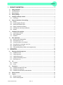
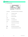
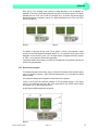
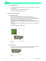
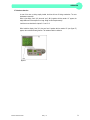
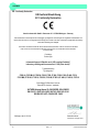
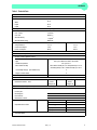
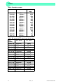
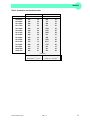
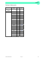
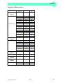
Operating manual for Table Top Centrifuge Z 446 © Hermle Labortechnik GmbH Z446_V1.14 CONTENT 1. PRODUCT DESCRIPTION ....................................................................................................1 1.1 Saftey instructions ................................................................................................................................................ 1 1.2 Intended purpose .................................................................................................................................................. 1 1.3 Brief discription..................................................................................................................................................... 1 1.4 Delivery package ................................................................................................................................................... 1 1.5 Operating and display elements ......................................................................................................................... 2 1.5.1 LCD-Display ........................................................................................................................................................ 3 1.6 Signs and indications of the centrifuge ............................................................................................................. 3 1.6.1 General ............................................................................................................................................................... 3 1.6.2 Product-nameplate (Example)............................................................................................................................ 4 1.6.3 Warning and information signs ........................................................................................................................... 5 1.6.4 Danger, precautions and warranty ..................................................................................................................... 5 1.6.5 Following rules must strictly be adhered to: ....................................................................................................... 6 1.6.6 Warranty ............................................................................................................................................................. 6 1.7 Installation of the centrifuge................................................................................................................................ 7 1.7.1 Unpacking the centrifuge .................................................................................................................................... 7 1.7.2 Space requirements ........................................................................................................................................... 7 1.7.3 Installation ........................................................................................................................................................... 7 1.8 Basic adjustments ................................................................................................................................................ 8 1.8.1 Access to mode "Operating Data" ...................................................................................................................... 8 1.8.2 Sound signal turn on / off ................................................................................................................................... 9 1.8.3 Volume pre-selection of sound signal ................................................................................................................ 9 1.8.4 Song selection for sound signal - end of run.................................................................................................... 10 1.8.5 Keyboard sound turn on / off ............................................................................................................................ 10 1.8.6 Call up operating data (by skilled or service engineer only!) ........................................................................... 11 2. OPERATION ........................................................................................................................12 2.1 Mounting and loading angle rotor .................................................................................................................... 12 2.1.1 Installation of rotors .......................................................................................................................................... 12 2.1.2 Loading angle rotors ......................................................................................................................................... 12 2.1.3 Loading swing out rotors .................................................................................................................................. 13 2.1.4 Loading and overloading of rotors.................................................................................................................... 14 2.1.5 Removing the rotor ........................................................................................................................................... 14 2.2 Lid ......................................................................................................................................................................... 15 2.2.1 Lid release ........................................................................................................................................................ 15 2.2.2 Lid lock .............................................................................................................................................................. 15 2.3 Preselection ......................................................................................................................................................... 16 2.3.1 Preselection of speed / RCF-value .................................................................................................................. 16 2.3.2 Preselection of running time ............................................................................................................................. 16 2.3.3 Preselection of brake intensity and acceleration ............................................................................................. 17 2.4 Radius correction................................................................................................................................................ 18 2.5 Program ................................................................................................................................................................ 18 2.5.1 Storage of programs ......................................................................................................................................... 18 2.5.2 Recall of stored programs ................................................................................................................................ 19 © Hermle Labortechnik GmbH Z446_V1.14 I CONTENT 2.5.3 Leaving program mode..................................................................................................................................... 20 2.6 Starting and stopping the centrifuge................................................................................................................ 20 2.6.1 Starting the centrifuge ...................................................................................................................................... 20 2.6.2 The "STOP" key................................................................................................................................................ 20 2.7 Imbalance detection ........................................................................................................................................... 21 3. MAINTENANCE ...................................................................................................................22 3.1 Maintenance and cleaning ................................................................................................................................. 22 3.1.1 General ............................................................................................................................................................. 22 3.1.2 Cleaning and disinfection of the unit ................................................................................................................ 23 3.1.3 Cleaning and disinfection of the rotor............................................................................................................... 23 3.1.4 Disinfection of aluminum rotors ........................................................................................................................ 23 3.1.5 Disinfection of PP-rotors ................................................................................................................................... 23 3.1.6 Glass breakage................................................................................................................................................. 24 3.2 Life time of rotors, round and rectangular buckets, accessories ................................................................. 24 4. TROUBLE SHOOTING ........................................................................................................25 4.1 Error message: Cause / Solution ...................................................................................................................... 25 4.2 Survey of possible error messages and their solutions ................................................................................ 25 4.2.1 Lid release during power failure (Emergency Lid Release) ............................................................................. 25 4.2.2 Description of the error message system ........................................................................................................ 26 5. RECEIPT OF CENTRIFUGES TO REPAIR ........................................................................27 6. TRANSPORT, STORAGE AND DISPOSAL .......................................................................28 6.1 Transport.............................................................................................................................................................. 28 6.2 Storage ................................................................................................................................................................. 28 6.3 Disposal ............................................................................................................................................................... 28 7. APPENDIX ............................................................................................................................III EG - Conformity Declaration ...................................................................................................................................... IV Table 1: Technical Data .............................................................................................................................................. V Table 2: Permissible net weight ................................................................................................................................. VI Table 3: Max. speed and RCF-values for permissible rotors .................................................................................... VI Table 4: Accelerations and deceleration times ......................................................................................................... VII Table 5: Error messages .......................................................................................................................................... VIII Table 6 (part 1): Radius correction............................................................................................................................. IX Table 6 (part 2): Radius correction.............................................................................................................................. X Table 6 (part 3): Radius correction............................................................................................................................. XI Table 6 (part 4): Radius correction............................................................................................................................ XII Table 7: Abbreviations used .....................................................................................................................................XIV Redemption form / Decontamination certificate .......................................................................................................XIV II Z446_V.14 © Hermle Labortechnik GmbH PRODUCT DISCRIPTION 1. PRODUCT DESCRIPTION 1.1 Saftey instructions This symbol indicates safety instructions and points to potential dangerous situations. Before using the centrifuge the first time, please read the operating manual. Failure to follow these instructions can result in personal injury an property damage . Intended use includes the observance of all instructions in the instruction manual and carrying out inspection and maintenance. 1.2 Intended purpose This Hermle centrifuge was designed only for the separation of materials or mixtures with different density, specifically for the preparation and processing of samples from the human body in context of an in-vitro-diagnostic use, to allow the use of in-vitro-diagnostic in accordance to its intended purpose. The designated device and its accessories listed in the technical documentation for this device are in accordance with Directive 98/79/EC on in-vitro-diagnostic medical devices. Hermle centrifuges are intended exclusively for indoor use and for use by qualified personnel. Only Hermle original rotors and accessories might be used. Any other use or intended use is considered improper. From the resulting damage the company Hermle Labortechnik is not liable. 1.3 Brief discription The unit type Z 446 is a non refrigerated universal centrifuge, which we offer in two voltage variations 230V or 120V. The centrifuge can be used with swing-out and angle rotors. All parameters are accessible via buttons and selected with the central adjuster. All pre-selected and current values will be shown permanently on the LCD-display. The centrifuge is powered by a maintenance-free induction motor. Detailed technical data are in "table 1 Technical data" (see APPENDIX P.V). 1.4 Delivery package • 1 Centrifuge Z 446 • 1 Operating Manual Z 446 • 1 Rotor key Rotor(s) / Accessories will be packed separate. © Hermle Labortechnik GmbH Z446_V1.14 1 PRODUCT DISCRIPTION 1.5 Operating and display elements 11 12 1 3 8 4 10 5 6 7 9 2 2 1 central adjuster run parameters 2 0-I power switch 3 LCD control panel display 4 rpm/rcf speed/ g-force 5 accel/decel acceleration- / deceleration intensity 6 time centrifugation time 7 lid lid release 8 quick short running 9 start start centrifugation 10 stop stop centrifugation 11 prog calling stored programs 12 store program store Z446_V1.14 © Hermle Labortechnik GmbH PRODUCT DISCRIPTION 1.5.1 LCD-Display The following picture shows the individual elements of the LCD-display. Figure 1 Display fields: A-1 Display field – „rpm/rcf“ A-2 Display field – „acc/dec“ A-3 Display field – „time“ Messages/logos of the display fields: 1.6 M1 „close“ M8 „decel“ M2 „open“ M9 „radius“ M3 „rotor“ M10 „program“ M4 Rotor-No. M11 „error“ M5 „rpm“ M12 „service“ M6 „rcf“ M13 h m s M7 „accel“ Signs and indications of the centrifuge 1.6.1 General Instructions for disposal (see P. 28) Direction of rotation – clockwise rotation for the rotor drive Reference for loading rotors © Hermle Labortechnik GmbH Z446_V1.14 3 PRODUCT DISCRIPTION 1.6.2 Product-nameplate (Example) Company address: Hermle Labortechnik GmbH, Siemensstr. 25, D-78564 Wehingen TYPE: Type designation of the product REF: Order no. of the product SN: Serial number of the product Date of manufacture MAX. Drehzahl: max. allowed speed of the unit KIN. EN.: max. kinetic energy with corresponding rotor U/I/f: Allowable voltage / max. current / frequency P: Electrical input power Before operating, read the operating manual! Labeling, standards and guidelines that are considered 4 Z446_V1.14 © Hermle Labortechnik GmbH PRODUCT DISCRIPTION 1.6.3 Warning and information signs Four carrier must be used at all times on four place swing out rotors or damage will occur to the centrifuge. Such damage will not be covered under the product warranty. Attention! Check the fastening of the rotor nut before each run. Take off mains plug before opening the housing or the emergency release 1.6.4 Danger, precautions and warranty This device may only be operated by trained specialist stuff. They must have carefully read the operating manual and be familiar with the function of the device. To protect people and environment the following precautions should be observed: • During centrifugation, the presence of people and the setting up of hazardous materials is prohibited within 30 cm around the centrifuge according to the regulations of EN 61010-2-020. • The HERMLE Z 446 is non explosion-proof and must therefore not be operated in explosionendangered areas or locations. Centrifugation of flammable, explosive, radioactive, or such substances, which chemically react with high energy, is strictly prohibited. The final decision on the risks associated with the use of such substances is the responsibility of the user of the centrifuge. • Never spin toxic or pathogenic material without adequate safety precautions, i.e. centrifugation of buckets / tubes without or with defective hermetic sealings is strictly prohibited. The user is obliged to perform appropriate disinfection procedures in case dangerous substances have contaminated the centrifuge and or its accessories. When centrifuging infectious substances, always pay attention to the General Laboratory Precautions. If necessary, contact your safety officer! • It is prohibited to run the centrifuge with rotors other than listed for this unit. • Under no circumstances open the lid of the centrifuge while the rotor is still running or rotating with a speed of > 2m/s © Hermle Labortechnik GmbH Z446_V1.14 5 PRODUCT DISCRIPTION 1.6.5 Following rules must strictly be adhered to: • Do not operate the centrifuge in case it is not installed correctly. • Do not operate the centrifuge when dismounted (e.g. without housing). • Do not run the centrifuge when mechanical or electrical assembly groups have been tampered with unauthorized persons. • Do not use accessories such as rotors and buckets, which are not exclusively approved by HERMLE Labortechnik GmbH, except commercially available centrifuge tubes made of glass or plastic. • Do not spin extremely corrosive substances, as they may cause material damages and impair mechanical resistance. • Do not operate the centrifuge with rotors or buckets, which show any signs of corrosion or mechanical damage. The manufacturer is responsible for safety and reliability of the centrifuge, only if: • the unit is operated in accordance with this instruction manual. • modifications, repairs or other adjustments are performed by HERMLE-authorized personnel and the electrical installation of the related location corresponds to the IEC-regulations. 1.6.6 Warranty The centrifuge has been subjected to thorough testing and quality controls. In the unlikely case of any manufacturing faults occurring, the centrifuge and rotors are covered by warranty for a period of two years from date of delivery. This warranty becomes invalid in case of mishandling, damage and negligence and further in case of usage of inappropriate spare parts and / or accessories or unauthorized modification of the unit. Technical modification rights are reserved by the manufacturer in respect to technical improvement! 6 Z446_V1.14 © Hermle Labortechnik GmbH PRODUCT DISCRIPTION 1.7 Installation of the centrifuge 1.7.1 Unpacking the centrifuge Model Z 446 is supplied in a carton. Remove the strap retainer, open the carton and remove the centrifuge. The instruction manual must always be kept with the centrifuge! 1.7.2 Space requirements The centrifuge should be installed on an even solid surface, if possible on a laboratory cabinet / table or some other solid vibration free surface. During centrifugation, the centrifuge must be placed in a way, that there is a minimum space of 30 cm on each side of the unit according to the standards EN 61010-2-020. Do not place the centrifuge next to a window or a heater, where it could be disposed to excessive heat, as the performance of the unit is based on an ambient temperature of 23°C. 1.7.3 Installation Follow these steps: • Check whether power supply corresponds with the one named on the manufacturer's rating label, which is mounted on the rear panel. • The line voltage circuit braker is max. 10 A (type K) slow release for commonly used instruments. • In case of emergency, there must be an emergency switch off installed outside the room in order to disconnect the power supply of the unit. • Connect the centrifuge with the mains. (The socket for the power cord must be easy to reach respectively easy to disconnect). Switching it on using the mains power switch (I). Open the lid by using the button LID. • Remove the transport securing device of the motor. © Hermle Labortechnik GmbH Z446_V1.14 7 PRODUCT DISCRIPTION 1.8 Basic adjustments At commissioning of the centrifuge, you have the options to make the following basic settings: - Acoustic signal turn on / off - Keyboard sound turn on -/ off - Volume pre-selection of sound signal - Song selection of sound signal „end of run“ 1.8.1 Access to mode "Operating Data" If the centrifuge is still turned off, press simultaneously the keys „time“ (6) and „lid“ (7) and turn on the main switch of the centrifuge. Now release both keys again. As a result a display test is executed for approx. 5 seconds. All possible indications will appear at the same time (see figure 2). Figure 2 Attention: - Please notice that you must enter the program as described under point 1.8.1 to change the adjustments of the points 1.8.2 - 1.8.6. After you have stored the settings you change the normal program mode again by switch off the centrifuge for a short while. - All changed settings must be confirmed by the key „start“ (9). As an optical confirmation appears the word „store“ in the display „rpm/rcf“(A-1) - Only then the pre-selections are valid! (see figure 3) Figure 3 8 Z446_V1.14 © Hermle Labortechnik GmbH PRODUCT DISCRIPTION 1.8.2 Sound signal turn on / off Proceed as described under point 1.8.1 to enter this program mode and then press the key „accel/decel“ (5). In the display „accel/decel“ (A-2) flashes the word „service“. Now select the letter „L“. with the adjusting knob (1). As a result appear in the display „rpm/rcf“ (4) the words „On Sound“. If you press the key „rpm/rcf“ (4) now, the word „On“ flashes and you can switch off the sound with the adjusting knob (1) (see figure 4). After you have stored the settings you changed to the normal program mode again by switch off the centrifuge for a short while. Firgure 4 1.8.3 Volume pre-selection of sound signal Proceed as described under point 1.8.1 to enter this program mode and then press the key „accel/decel“ (5). In the display „accel/decel“ (A-2) flashes the word „service“. Now select the letter „U“ with the adjusting knob (1). As a result appear in the display „rpm/rcf“ (A-1) the words „Vol=0-9/Sound“. After pressing the key „rpm/rcf“ (4), you can adjust the desired volume between 0 (low) and 9 (loud) with the adjusting knob (1) (see figure 5). After you have stored the settings (see 1.8.1) you changed to the normal program mode again by switch off the centrifuge for a short while. Figure 5 © Hermle Labortechnik GmbH Z446_V1.14 9 PRODUCT DISCRIPTION 1.8.4 Song selection for sound signal - end of run Proceed as described under point 1.8.1 to enter this program mode and then press the key „accel/decel“ (5). In the display „accel/decel“ (A-2) flashes the word „service“. Now select the letter „G“. with the adjusting knob (1). As a result appears in the display „rpm/rcf“ (A-1) the word „ SonGo/Sound“. After pressing the key „rpm/rcf“ (4), you can select a song with the adjusting knob (1). (see figure 6). After you have stored the settings (see 1.8.1) you changed to the normal program mode again by switch off the centrifuge for a short while. Figure 6 1.8.5 Keyboard sound turn on / off Proceed as described under point 1.8.1 to enter this program mode and then press the key „accel/decel“ (5). In the display „accel/decel“ (A-2) flashes the word „service“. Now select the letter „b“. with the adjusting knob (1). As a result appears in the display „rpm/rcf“ (A-1) the word „ON/BEEP“. After pressing the key „rpm/rcf“ (4), you can turn the keyboard sound (On) or (Off) with the adjusting knob (1). (see figure 7). After you have stored the settings (see 1.8.1) you changed to the normal program mode again by switch off the centrifuge for a short while. Figure 7 10 Z446_V1.14 © Hermle Labortechnik GmbH PRODUCT DISCRIPTION 1.8.6 Call up operating data (by skilled or service engineer only!) In the mode „Basic Adjustments“ you can call up the operating data of the centrifuge. Please proceed as described under point 1.8.1 to enter this program mode. Press the key „accel/decel“ (5). In the display „accel/decel“ (A-2) flashes the word „service“. With the adjusting knob (1) the different information can be called up: A = previous starts of the centrifuge H = previous operating hours S = software version r = converter software E = list of previous error massage h = running time of the motor The list of the last 99 error messages can be looked over by pressing the key „rpm/rcf“ (4) and scroll through it by the adjusting knob (1). The respective error codes appear in the display „rpm/rcf“ (A-1). Please look up in „Table 5: error messages“ (see APPENDIX S. VIII). Here as well you must shortly switch off the centrifuge for changing to the normal program mode again. Figure 8 © Hermle Labortechnik GmbH Z446_V1.14 11 OPERATION 2. OPERATION 2.1 Mounting and loading angle rotor 2.1.1 Installation of rotors Clean the drive shaft as well as the collet with a clean, grease-free piece of cloth. Place the rotor onto the drive shaft. (see figure 9) Take care that the rotor is fully installed onto the motor shaft. Figure 9 Figure 10 Hold the rotor with one hand and secure the rotor to the shaft by turning the fixing nut clockwise. Tighten fixing nut with enclosed allen key (see figure 10) Figure 11 ATTENTION: For safety always ensure that rotor fixing screw is tightened before each run!! (see figure 10) 2.1.2 Loading angle rotors Rotors must be load symmetrically and with equal weight (see figure 12+13). The adapter may only be load with the appropriate vessels. The weight differences between the filled vessels are as low as possible to keep. Therefore we recommend to weighting with a balance. This reduces the wear of drive and the acoustic operating noise. On each rotor is designated how large the maximum load per hole is. (It is allowed to operate e.g. a 12-place-rotor with 2 or 4 loaded tubes only. But the loaded borings must be opposite each other). 12 Z446_V1.14 © Hermle Labortechnik GmbH OPERATION Figure 12: WRONG Figure 13: CORRECT (4 tubes) 2.1.3 Loading swing out rotors Loading of the buckets / vessels must be made in accordance to figure 15 It is allowed to operate e.g. a 4-place-rotor with 2 loaded buckets only. But the loaded buckets must be opposite to each other. Make sure that the unloaded buckets also be put inside the rotor (see figure 14 and 15). In principle swing out rotors may not be taken in operation until all buckets or racks are put into the rotor. The bolts at the rotor must be greased with the HERMLE High TEF oil (Order No. 34-5147). The sample tubes have to be filled evenly by eye and put into the drillings or tube racks. The weight difference of the loaded buckets should not exceed approx. 1,0 g. ATTENTION! Swing out rotors may be taken in operation only if all locations are filled in with either four buckets or four carriers – do not mix buckets and carriers up!! Figure 14: WRONG Figure 15: CORRECT ATTENTION! Do not operate the centrifuge with rotors or buckets which show any signs of corrosion or mechanical damage. Do not operate with extremely corrosive substances, which could damage the rotor and buckets. In case of any questions, please contact the manufacturer! © Hermle Labortechnik GmbH Z446_V1.14 13 OPERATION 2.1.4 Loading and overloading of rotors All approved rotors are listed with their maximum speed and maximum filling weight in „table 2: permissible net weight“ (see APPENDIX P. VI). The maximum load permitted for a rotor, which is determined by the manufacturer, as well as the maximum speed allowed for this rotor (see label on rotor), must not be exceeded. The liquids the rotors are loaded with, should have an max. homogeneous density of 1,2 g/ml or less when the rotor is running at maximum speed. In order to spin liquids with a higher density, the speed has to be reduced according to the following formula: , Reduced speed nred = x max. speed (nmax) of the rotor Example: nred = , , x 4.000 = 3.360 rpm If In case of any questions, please contact the manufacturer! 2.1.5 Removing the rotor Untighten the rotor fixing nut complete and lift the rotor vertical out of the centrifuge. (see figure 9 and 10) 14 Z446_V1.14 © Hermle Labortechnik GmbH OPERATION 2.2 Lid 2.2.1 Lid release After the run, respectively closing the lid of the centrifuge, it appears in the display „rpm/rcf“(A-1) the word „close“ (M1). If there is a rotor in the centrifuge, it appears additional the word „rotor“ (M3), as well as the code number of the respective rotor, which is in the centrifuge i. e. „221.28“ (M4). If there is no rotor in the centrifuge it flashes the word „rotor“ (M3) and additional the word „no“ (M4). ). By pressing the key „lid“ (7) you can release the lid of centrifuge. As soon as the electromagnetic lid is completely released, it appears the word „open“ (M2). Now you can open the lid of the centrifuge. All with number marked passages refer to figure 16 Figure 16 During the run you can call up the rotor type at any time by pressing the key “lid” (7). 2.2.2 Lid lock The lid must only be lay down slightly. An electromagnetic lid lock closes the lid, at the same time disappears the word „open“ (M2). As a sign that the centrifuge is ready for starting it appears in the display „rpm/rcf“(A-1) the word „close“ (M1). Simultaneously it appears in that display the word „rotor“ (M3), as well as the code number of the rotor, which is in the centrifuge i. e. „nr 22x.xx“ (M4). With that all rotor specifically data, like e. g. max. speed, acceleration etc., are adopted. All with number marked passages refer to figure 16 ATTENTION: Don't grip your fingers between lid and device or locking mechanism when closing the lid! © Hermle Labortechnik GmbH Z446_V1.14 15 OPERATION 2.3 Preselection 2.3.1 Preselection of speed / RCF-value Through the key „rpm/rcf“ (4) this pre-selection is activated. By pressing the key once the word „rpm“ (M5) flashes. By pressing the key once again the pre-selection of the centrifugal forces may be chosen. Then it appears the flashing word „rcf“ (M6). You can set the desired values with the adjusting knob (1). In the display (A-1) the regulated value is shown permanently, before, during and after the run. All with number marked passages refer to figure 17 Figure 17 As long as no rotor is inserted, the speed is adjustable between 200 rpm and maximum revolution of the centrifuge. If there is a rotor in the centrifuge the speed can only be pre-selected until the maximum permissible revolution of that rotor. It is the same with the pre-selection of the RCF-value. The setting range is between 20 xg and the maximum permissible centrifugal force of the rotor. See „table 3: max. speed and RCF-values for permissible rotor“ (see APPENDIX P. VI). There are listed all important values. ATTENTION: Please also check the maximum permissible revolutions of your test tubes! (Producer Indication) 2.3.2 Preselection of running time The running time can be pre-selected in three different ranges from 10 seconds up to 99 hours 59 minutes. 1. Range from 10 seconds up to 59 minutes 50 seconds in steps of 10 seconds 2. Range from 1 hour up to 99 hours 59 minutes in steps of 1 minutes 3. Range continuous run „cont”, which can be interrupted by the key “stop” (10). The running time can be pre-selected with the lid open or closed. To activate the setting of the running time press the key „time“ (6). 16 Z446_V1.14 © Hermle Labortechnik GmbH OPERATION In the display „time“ (A-3) flashes the indication „m : s“ or „h : m“, depending on the previous setting. To set the desired value use the adjusting knob (1). After exceeding of 59 min 50 sec the indication changes automatically into „h : m“. After exceeding of 99 hours 59 min the word „cont” appears in the display „time” (A-3). That continuous run can only be interrupted by pressing the key „stop” (10). The time countdown as soon as the set speed is reached. The display shows always the remaining running time. (see figure 18) All with number marked passages refer to figure 18 Figure 18 2.3.3 Preselection of brake intensity and acceleration Through the key „accel/decel“ (5) this function is activated. By pressing the key once the word „accel“ (M7) flashes in the display „accel/decel“ (A-2). The desired acceleration can be pre-selected by the adjusting knob (1). The value 0 is equivalent to the lowest and the value 9 to the highest acceleration. By pressing the key „accel/decel“ (5) twice, in the display „accel/decel“ (A-2) indicates the word „decel“ (M8). Now the desired brake intensity can be pre-selected by the adjusting knob (1). The value 9 is equivalent to the shortest and the value 0 to longest possible brake time. All with number marked passages refer to figure 19 See „table 4: acceleration and deceleration times“ (APPENDIX P. VII). There are shown the acceleration and deceleration times for the acceleration and deceleration stages 0 to 9 for permissible rotors. Figure 19 © Hermle Labortechnik GmbH Z446_V1.14 17 OPERATION 2.4 Radius correction If you use adapters or reducers it could change the centrifugal radius of the respective rotor. In that case you can correct the radius manually. Please proceed as follows: Press the key „time“ (6) and the key „prog“ (11) at the same time and hold them. In the display „time“ (A-3) appears the word „radius“ (M9). By the adjusting knob (1) you can preselect then the respective radius correction (see table 6, APPENDIX P. IX) in steps of 0,1 cm. As soon as you have set a radius correction the word „radius“ (M9) appears. This hint is as long visible as you put the radius correction back to 0 again. All with number marked passages refer to figure 20 Figure 20 2.5 Program 2.5.1 Storage of programs You can store up to 99 runs with all relevant parameters, incl. the used rotors. You can use any free program number and call it up again. Put the needed rotor into the centrifuge. By pressing the key „prog“ (11) in the display „time“ (A-3) appears the word „program" (see figure 21). With the adjusting knob (1) you can chose the desired program number. If a program number is already occupied in the display „rpm/rcf“ (A-1) will appear the words „rotor” (M3) and „22x.xx“ (M4) (see figure 21). In case of free program numbers it appears 0. Figure 21 18 Z446_V1.14 © Hermle Labortechnik GmbH OPERATION Close the lid of the centrifuge. Now proceed as already described to set all important run parameters. If the lid isn´t closed when storing the programm, in the display "rpm/rcf" (A-1) flashes alternately the word "FirSt" and "CLOSE Lid" (see figure 22). If you want to start the run without storing the programm, in the display "rpm/rcf" (A-1) flashes alternately the word ""First" and "PrESS StoreE" (see figure 23). Figure 22 Figure 23 For adaption of data press the key „store“ (12) for approx. 1 second. If the programm is stored correctly, the word StorE appears in the display "rpm/rcf" (A-1). As a result the word „program“ (M10) disappears. As soon as the key „store“ (12) is no longer anymore, it reappears the word „programm xx“ (M10) – the (xx) stands for the chosen program place. If all program numbers are occupied you can take an old number that is not necessary anymore and just put in the new parameters. 2.5.2 Recall of stored programs To recall stored programs press the key „prog“ (11) while the lid is already closed. Inside the display „time“ (A-3) appears „programm --“(M10). With the adjusting knob (1) you pre-select the desired program number. In the respective displays there will appear the stored values for that program. If there is not the right rotor inside the centrifuge for the pre-selected program, in the display „rpm/rcf“ (A-1) flashes the word „rotor“ (M3). At the same time the word „FALSE“ and the stored rotor number „22x. xx“ (M4) will flashing by turns. All with number marked passages refer to figure 24. Figure 24 © Hermle Labortechnik GmbH Z446_V1.14 19 OPERATION 2.5.3 Leaving program mode To leave the program mode just press the key „prog“ (11). Then inside the display „time“ appears the word „programm". Set the display to „programm--“ (M10) with the adjusting knob (1). All with number marked passages refer to figure 24. 2.6 Starting and stopping the centrifuge 2.6.1 Starting the centrifuge You can start the centrifuge either with the „start“ key (9) or the „quick“ key (8). By the „start“ key (9) you can start stored runs or runs with manually pre-selected parameters. When the respective pre-selected running time has ended then the centrifuge will stop automatically. By the „quick“ key (8) you can start runs, which will last just a few seconds. By pressing the „quick” key (8) the centrifuge accelerates up to the pre-selected revolution. In the display „time“ (A-3) the passed running time is indicated from the date of pressing the „quick” key (8). By releasing the „quick” key (8) the centrifuge stops and the running time is indicated until the opening of the lid. All with number marked passages refer to figure 25 Figure 25 2.6.2 The "STOP" key By the „stop“ key (10) (see figure 26) you can interrupt the run at any time. After pressing the key the centrifuge decelerates with the respective pre-selected intensity down to stand still. Figure 26 20 Z446_V1.14 © Hermle Labortechnik GmbH OPERATION 2.7 Imbalance detection In case of the rotor not being equally loaded, the drive will turn off during acceleration. The rotor decelerates to stand still. When in the display “time” (A-3) the word “error” (M11) together with the number “01” appear, the weight difference of the samples is too huge. Weigh out the samples exactly! Load the rotor as described in chapter 2.1.2 and 2.1.3. When inside the display “time” (A-3) the word “error” together with the number “02“ (see figure 27) appear, there could be following reasons: The imbalance switch is defective. Figure 27 © Hermle Labortechnik GmbH Z446_V1.14 21 MAINTENANCE 3. MAINTENANCE 3.1 Maintenance and cleaning 3.1.1 General Care: Maintenance of the centrifuge is confined to keeping the rotor, the rotor chamber and the rotor accessories clean as well as to regularly lubricating the rotor insert bolts of a swing out rotor (if available). Lubricants containing molycote and graphite are not allowed. Please pay special attention to anodized aluminum parts. Breakage of rotors can be caused even by slightest damages. In case of rotors, buckets or tube racks getting in touch with corrosive substances the concerned spots have to be cleaned carefully. Corrosive substances are for instance: alkalis, alkaline soap solutions, alkaline amines, concentrated acids, solutions containing heavy metals, water-free chlorinated solvents, saline solutions, e.g. salt water, phenol, halogenated hydrocarbons. Cleaning – units, rotors, accessories: - Turn the device off and disconnect it from the power supply before you begin any cleaning or disinfecting. Do not pour liquids into the housing interior. Do spray disinfectant on the device. Thorough cleaning not only has its purpose in hygiene but also in avoiding corrosion based on pollution. In order to avoid damaging anodized parts such as rotors, reduction plates etc., only pH-neutral Detergents with a pH-value of 6-8 may be used for cleaning. Alkaline cleaning agents (pH-value > 8) must not be used. After cleaning, please ensure all parts are dried thoroughly, either by hand or in a hot-air cabinet (max. Temperature + 50°C). It is necessary to coat anodized aluminium parts with anti-corrosion oil regularly in order to increase their life-spans and reduce corrosion predisposition. Due to humidity or not hermetically sealed samples, condensate may be formed. The condensate has to be removed from the rotor chamber with a soft cloth regularly. The maintenance procedure has to be repeated every 10 to 15 runs, but at least once a week! - 22 Connect the unit to the power supply, after the equipment is completely dry. Do not carry out disinfection with UV-, beta- and gamma-rays or other high energy radiation. Metal rotors can be autoclaved. Rotor lid and adapters can also be autoclaved (max. 121°C, 20 min). The tube racks are made of PP and cannot be autoclaved at 134°C. Z446_V1.14 © Hermle Labortechnik GmbH MAINTENANCE 3.1.2 Cleaning and disinfection of the unit 1. 2. 3. 4. 5. 6. 7. 8. 9. Open the lid before you turn off the unit. Disconnect it from the power supply. Open the rotor nut by turning the rotor key counter clockwise. Remove the rotor. For cleaning and disinfection of the unit and the rotor chamber using the above mentioned cleaner. Clean all accessible areas of the device and its accessories, including the power cord with a damp cloth. Wash the rubber seals and rotor chamber thoroughly with water. Rub the dry rubber seals with glycerol or talc to prevent these to becoming brittle. Other components of the unit, e.g. the lid lock, motor shaft and rotor must not be greased. Dry the motor shaft with a soft, dry and lint-free cloth. Control the unit and accessories for damage. Remove at least every six months adherent dust from the ventilation slots in the centrifuge by using a soft brush. Before doing that, please switch off the unit and disconnect the unit from the power supply. 3.1.3 Cleaning and disinfection of the rotor 1. 2. 3. 4. Clean and disinfect the rotors, rotor lids and adapters with the above mentioned cleaner. Use a bottle brush to clean and disinfect the rotor bores. Rinse the rotors, rotor lid and adapter with clear water. Particular the drillings of angle rotors. For drying of the rotors and accessories set them on a towel. Place the angle rotors with bores down, to dry them to. 5. Dry the rotor cone with a soft, dry and lint-free cloth and look for damage. Do not grease the rotor cone. 3.1.4 Disinfection of aluminum rotors In case of infectious material spilling into the centrifuge, the rotor and rotor chamber have to be disinfected right after the run. Rotors may be autoclaved at a maximum temperature of 121°C. 3.1.5 Disinfection of PP-rotors Autoclaving The recommended time for autoclaving: 15 – 20 min at 121°C (1 bar) ATTENTION: The sterilization time of 20 min. must not be exceeded. Sterilization again and again will cause reduction of the mechanical resistance of the plastic material Before the autoclaving the PP-rotor and adapter must thoroughly be cleaned to avoid the burning in of dirty residues. You can disregard the consequences of some chemical residues to plastic materials at ambient temperatures. But at the high temperatures of the autoclaving those residues may corrode and destroy the plastic. The objects must be thoroughly washed up with distilled water after the cleaning but before the autoclaving. Residues of any cleaning liquids may cause fissures, whitening and stains. © Hermle Labortechnik GmbH Z446_V1.14 23 MAINTENANCE Gas sterilization Adapters, bottles and rotors may be gas sterilized with Ethylenoxyd. According to the duration of the application you may give long enough an airing to the items after the sterilization and before using them again. ATTENTION: Because the temperature may rise during the sterilization, rotors, adapters and bottles must not be closed respectively must be totally unscrewed Chemical sterilization Bottles, adapters and rotors may be treated with the usual liquid disinfectants. ATTENTION: Before applying any other cleaning resp. Decontamination method than recommended by the manufacturer, contact the manufacturer to ensure that it will not damage the unit or the rotor. 3.1.6 Glass breakage With high g-values, the rate of glass tube breakage increases. Glass splinters have to be removed immediately from rotor, buckets, adapters and the rotor chamber itself. Fine glass splinters will scratch and therefore damage the protective surface coating of a rotor. If glass splinters remain in the rotor chamber, fine metal dust will build up due to air circulation. This very fine, black metal dust will extremely pollute the rotor chamber, the rotor, the buckets and the samples. If necessary, replace the adapters, tubes and accessories to avoid further damages. Check the rotor bores regularly for residues and damages. ATTENTION: Please check the relevant specifications of the tubes centrifuges with the manufacturer! 3.2 Life time of rotors, round and rectangular buckets, accessories Rotors and rotor lid made of aluminum or stainless steel, have a operating time of max. 7 years from first use. Transparent rotor lids and caps made of PC or PP as well as rotors, tube racks and adapters of PP have a maximum operating time up to 3 years from first use. Condition for the operating time: Proper use, damage-free condition, recommended care. 24 Z446_V1.14 © Hermle Labortechnik GmbH TROUBLE SHOOTING 4. TROUBLE SHOOTING 4.1 Error message: Cause / Solution The error messages are listed to help localize possible errors faster. The diagnose referred to this chapter may not always be the case, as they are only theoretically occurring errors and solutions. Always, please keep us informed about any kind of error occurring, which is not listed in this chapter. Only through your information we are able to improve and complete this operation manual. Many thanks in advance for your support. HERMLE Labortechnik GmbH 4.2 Survey of possible error messages and their solutions 4.2.1 Lid release during power failure (Emergency Lid Release) In case of power failure or malfunction, the lid of the centrifuge can be opened manually in order to protect your samples. Please proceed as follows (see figure 28): • • • • • • Switch the centrifuge off and unplug the power cord, wait until the rotor stands still (this may take several minutes) At the left side of the centrifuge housing there is a plastic stopper. Remove this stopper and behind it there is a hexagon nut. Take the delivered box spanner, put him in the hole and lock the box spanner with hexagon nut (see figure 28). Now turn the box spanner to the right side (clockwise) up to the limit. ATTENTION: Just turn to the limit, don´t tighten the nut. Now open the lid of the centrifuge. Switch the centrifuge on again, for go on working. Figure 28 © Hermle Labortechnik GmbH Z446_V1.14 25 TROUBLE SHOOTING 4.2.2 Description of the error message system The error message „error“ (M11) is shown in the „time“ (A-3) display (see figure 29). Detailed information about possible error messages are in „table 5: error messages" (see Appendix P.VIII). Figure 29 26 Z446_V1.14 © Hermle Labortechnik GmbH REPAIR 5. RECEIPT OF CENTRIFUGES TO REPAIR Health risk from contaminated equipment, rotors and accessories In case of returning the centrifuge for repairing to the manufacturer, please notice the following: The centrifuge must be decontaminated and cleaned before the shipment for the protection of persons, environment and material. Decontamination certificate at goods return delivery (see APPENDIX P. XIV) We reserve the right to accept contaminated centrifuges. Further on all costs occurred for the cleaning and disinfection of the units will go to the debit of the customer’s account. © Hermle Labortechnik GmbH Z446_V1.14 27 TRANSPORT, STORAGE AND DISPOSAL 6. TRANSPORT, STORAGE AND DISPOSAL 6.1 Transport Before transporting, take out the rotor. Only transport the unit in the original packaging. Use a transport aid for transporting over longer distances to fix the motor shaft. General transportation Air temperature rel. humidity Air pressure ‐25 bis 60 °C 10 bis 75 % 30 bis 106 kPa 6.2 Storage During storage of the centrifuge the following environmental conditions must be observed: in transport packaging Air temperature rel. Humidity Air pressure ‐25 bis 55 °C 10 bis 75 % 70 bis 106 kPa 6.3 Disposal In the event of disposing of the product, please observe the applicable legal regulations. Information on the disposal of the electrical and electronic devices in the European Community:. The disposal of the electrical devices is regulated within the European Community by national regulations based on EU Directive 2002/96/EC pertaining to waste electrical and electronic equipment (WEEE). In accordance with this, any devices delivered after 13/08/2005 on a business-to-business basis, which includes the product, may no longer be disposed of in household waste. To document this they have been marked with the following identification: Because disposal regulations may differ from one country to another within the EU please contact your supplier if necessary. 28 Z446_V1.14 © Hermle Labortechnik GmbH APPENDIX 7. APPENDIX EG - Conformity Declaration ............................................................................................... IV Table 1: Technical Data ........................................................................................................ V Table 2: Permissible net weight .......................................................................................... VI Table 3: Max. speed and RCF-values for permissible rotors ........................................... VI Table 4: Accelerations and deceleration times ................................................................ VII Table 5: Error messages.................................................................................................... VIII Table 6 (part 1): Radius correction ..................................................................................... IX Table 6 (part 2): Radius correction ...................................................................................... X Table 6 (part 3): Radius correction ..................................................................................... XI Table 6 (part 4): Radius correction .................................................................................... XII Table 6 (part 5): Radius correction ................................................................................... XIII Table 7: Abbreviations used ............................................................................................. XIV Redemption form / Decontamination certificate ............................................................. XIV © Hermle Labortechnik GmbH Z446_V1.14 III APPENDIX EG - Conformity Declaration EG Konformitätserklärung EC Conformity Declaration Hermle Labortechnik GmbH - Siemensstr. 25 - D-78564 Wehingen – Germany Das bezeichnete Produkt entspricht den einschlägigen grundlegenden Anforderungen der aufgeführten EG-Richtlinien und Normen. Bei einer nicht mit uns abgestimmten Änderung des Produktes oder einer nicht bestimmungsgemäßen Anwendung verliert diese Erklärung ihre Gültigkeit. The Product named below fulfills the relevant fundamental requirements of the EC directives and standards listed. In the case of unauthorized modifications to the product or an unintended use this declaration becomes invalid. Produkttyp Product type Laborzentrifugen mit Zubehör nach „IVD (sonstige Produkte)” Laboratory centrifuge with accessories to “IVD (other device)” Typenbezeichnung Typ designation Z 206 A; Z 233 M-2; Z 216 M; Z 306; Z 326; Z 366; Z 383; Z 400; Z 446; Z 513; Z 216 MK; Z 32 HK; Z 326 K; Z 366 K; Z 36 HK; Z 383 K; Z 446 K; Z 400 K; Z 513 K Einschlägige EG-Richtlinien / Normen Relevant EC directives / standards 98/79/EG(Anhang/Annex III); 2006/95/EG; 2004/108/EG EN 61010-1; EN 61010-2-020: 2007-03; EN 61010-2-101 DIN EN ISO 14971; DIN EN ISO 13485 Wehingen, den 01.05.2014 Alexander Hermle Geschäftsführer, Managing Director IV Z446_V1.14 © Hermle Labortechnik GmbH APPENDIX Table 1: Technical Data HERMLE Labortechnik GmbH Z 446 Manfacturer Type Dimensions Width Depth Height Weight without rotor max. speed max. volume max. RCF allowable density allowable kinetic energy 54 cm 67 cm 39 cm 79 kg -1 16000 min 4 x 750 ml 24328 x g 3 1,2 kg/dm 60629 Nm 230 V / 50-60 Hz 1 ph Mains power connection AC Voltage fluctation Current consumption Power consumption Radio interference Audit requirement (BGR 500) Ambient conditions (EN/IEC 61010-1) 120 V / 50-60 Hz 1 ph ± 10 % 5,6 A 680 W ± 10 % 2,8 A 640 W IEC 61326-1 yes for indoor use only - Environement - High - Ambient temperature - Max. relative humidity - Overvoltage category (IEC 60364-4-443) Use up to an altitude of 2000 m above MSL 2°C up to 35 °C Max. relative humidity 80 % for temperatures up to 31°C, decreasing linearly to 50 % relative humidity up to 35°C. II - Degree of contamination Class of protection 2 I Not suitable for use in hazardous environements. EMV Interference emission , noise Noise level (depending on the rotor) Write from operator EN / IEC 61326-1 Category B ≤ 65 dB(A) FCC Class B EN / IEC FCC Class B 61326-1 Category B Inventory-No.: Monitoring-No.: Environement: Maintenance contract: responsible service office HERMLE Labortechnik GmbH Siemensstrasse 25 78564 Wehingen Tel.: (49)7426 / 96 22-17 Fax: (49)7426 / 96 22-49 or dealer service office responsible dealer © Hermle Labortechnik GmbH Z446_V1.14 V APPENDIX Table 2: Permissible net weight rotor-number 220.86 V02 221.08 V04 221.16 V03 221.17 V03 221.18 V02 221.20 V02 221.21 V02 221.22 V02 221.28 V02 221.36 V02 221.51 V02 221.52 V02 221.38 V01 220.87 V09 220.87 V10 max. speed 4500 min-1 4500 min-1 4500 min-1 15000 min-1 11000 min-1 15000 min-1 8000 min-1 13000 min-1 12000 min-1 4000 min-1 8000 min-1 10000 min-1 15000 min-1 16000 min-1 16000 min-1 permissible weight 1420 g 2832 g 620 g 106 g 840 g 560 g 2130 g 492 g 160 g 3980 g 2832 g 760 g 14 g 85 g 85 g Table 3: Max. speed and RCF-values for permissible rotors rotor number 220.86 V02 221.08 V04 221.16 V03 221.17 V03 221.18 V02 221.20 V02 221.21 V02 221.22 V02 221.28 V02 221.36 V02 221.51 V02 221.52 V02 221.38 V01 220.87 V09 220.87 V10 VI max. speed RCF value 4500 min-1 4500 min-1 4500 min-1 15000 min-1 11000 min-1 15000 min-1 8000 min-1 13000 min-1 12000 min-1 4000 min-1 8000 min-1 10000 min-1 15000 min-1 16000 min-1 16000 min-1 3894xg 4211xg 2716xg 23645xg 15552xg 23142xg 10017xg 15871xg 15777xg 3434xg 10375xg 14532xg 15342xg 24328xg 24328xg Z446_V1.14 © Hermle Labortechnik GmbH APPENDIX Table 4: Accelerations and deceleration times rotor-number 220.86 V02 221.08 V04 221.16 V03 221.17 V03 221.18 V02 221.20 V02 221.21 V02 221.22 V02 221.28 V02 221.36 V02 221.51 V02 221.52 V02 221.38 V01 220.87 V09 220.87 V10 Acceleration values Deceleration values level 0 level 9 level 0 level 9 252 320 249 221 463 448 573 264 305 483 575 480 100 204 205 26 35 27 23 48 50 66 28 32 47 73 60 12 21 21 560 751 488 561 1654 1251 1903 921 988 1287 2317 1747 201 421 421 28 34 23 30 46 45 84 32 37 49 82 68 12 30 29 in seconds Acceleration time ‐1 from 0 min ‐> Umax © Hermle Labortechnik GmbH Deceleration time from Umax ‐> 0 min Z446_V1.14 ‐1 VII APPENDIX Table 5: Error messages Error-No.: Description 1 Imbalance arose 2 Imbalance sensor is defective 4 Imbalance switch has been activated for longer than 5 seconds 8 Transponder in the rotor is defective 11 Temperature sensor is defective 12 Chamber over temperature 14 Leap of speed is too big between two measurements CLOSE lid 33 34 38 40 Open lid while motor is running Lid contact defective Lid motor is blocked Communication with frequency converter distrubed during start 41 Communication with frequency converter distrubed during stop 42 Short circuit in the frequency converter 43 Undervoltage frequency converter 44 Overvoltage frequency converter 45 Over temperature frequency converter 46 Over temperature motor 47 Over current frequency converter 48 Timeout between control unit and frequency converter 49 Other error frequency converter 55 Overspeed 70 Timeout between controler and RS232 interface 99 Rotor is not allowed in this centrifuge FALSE rotor no VIII Inserted rotor does not exist in the programm Rotor is not detected Z446_V1.14 © Hermle Labortechnik GmbH APPENDIX Table 6 (part 1): Radius correction Rotor No. Adapter/Tuberack Order‐No. Radius (cm) Correction (cm) Swing out rotor 220.86 610.000 17,4 0 Rectangle bucket 710.000 710.001 710.002 710.003 710.004 710.005 710.006 710.007 710.008 710.009 710.010 710.011 710.012 710.013 710.014 710.015 710.016 710.017 710.018 710.019 710.020 710.021 710.022 17,1 17,4 16,8 16,9 16,7 16,7 16,9 17,1 17,1 16,7 16,4 17,1 17,1 16,4 16,4 17,0 17,0 16,9 16,9 16,3 16,9 16,9 16,7 0,3 0,0 0,6 ‐0,5 ‐0,7 ‐0,7 ‐0,5 ‐0,3 ‐0,3 ‐0,7 1 ‐0,3 ‐0,3 ‐1,0 ‐1,0 ‐0,4 ‐0,4 ‐0,5 ‐0,4 ‐1,1 ‐0,5 ‐0,5 ‐0,7 © Hermle Labortechnik GmbH Z446_V1.14 IX APPENDIX Table 6 (part 2): Radius correction Rotor No. Swing out rotor Adapter/Tuberack Radius (cm) Order. No. Correction (cm) 611.000 17,3 0 711.003 711.004 711.005 711.006 711.007 711.008 711.009 711.010 711.011 713.001 713.002 713.003 713.004 713.005 713.006 713.007 713.008 713.009 713.010 713.011 713.021 713.022 17,0 17,0 17,1 17,3 17,0 17,0 17,2 16,9 16,9 17,1 17,1 17,1 16,8 16,6 16,8 17,1 17,1 17,3 17,1 17,1 ‐0,3 ‐0,3 ‐0,2 0,0 ‐0,3 ‐0,3 ‐0,1 ‐0,4 ‐0,4 ‐0,2 ‐0,2 ‐0,2 ‐0,5 ‐0,7 ‐0,5 ‐0,2 ‐0,2 0,0 ‐0,2 ‐0,2 16,8 ‐0,5 220.86 Round bucket X Z446_V1.14 © Hermle Labortechnik GmbH APPENDIX Table 6 (part 3): Radius correction Rotor No. Adapter/Tuberack Order. No. Radius (cm) Correction (cm) Swing out rotor 221.08 625.006 18,2 0 625.000 625.001 625.002 625.003 625.004 625.005 625.006 625.007 625.008 625.009 625.010 625.013 625.014 625.015 625.018 625.019 625.020 625.021 18,2 18,0 18,1 17,9 17,7 17,0 18,3 18,3 18,4 13,9 16,9 11,9 17,3 17,4 18,1 16,5 15,3 13,5 0,0 ‐0,2 ‐0,1 ‐0,3 ‐0,5 ‐1,3 0,1 0,1 0,2 ‐4,3 ‐1,3 ‐6,3 ‐0,9 ‐0,8 ‐0,1 ‐1,7 ‐2,9 ‐4,7 625.023 18,1 10,2 ‐0,1 0 706.000 10,2 9,5 0 0 704.004 704.005 9,1 8,4 ‐0,4 ‐1,1 Swing out rotor 221.16 Angle rotor 221.17 © Hermle Labortechnik GmbH Z446_V1.14 XI APPENDIX Table 6 (part 4): Radius correction Rotor No. Angle rotor 221.18 Angle rotor 221.20 Radius (cm) Correction (cm) 11,2 0 707.000 9,7 11,1 10,6 10,4 10,9 10,6 10,4 10,4 9,2 ‐1,5 ‐0,1 ‐0,6 ‐0,8 ‐0,3 ‐0,6 ‐0,8 ‐0,8 0 8,5 8,4 8,9 8,6 8,3 7,5 9,1 14,1 ‐0,7 ‐0,8 ‐0,3 ‐0,6 ‐0,9 ‐1,7 ‐0,1 0 ‐4,2 ‐0,6 ‐4,1 ‐0,8 ‐4,1 ‐1,0 ‐4,2 ‐1,6 ‐2,1 ‐2,4 0 ‐0,5 ‐0,4 ‐0,7 ‐0,2 0 707.001 707.002 707.003 707.004 707.014 707.015 707.001 707.002 707.003 707.004 707.014 707.000 Angle rotor 221.21 713.015 713.020 713.025 713.028 713.030 713.042 9,9 13,5 10 13,3 10 13 9,9 12,5 12 11,7 8,4 708.003 708.004 708.017 708.019 7,9 8 7,7 8,2 9,9 Angle rotor 221.22 Angle rotor 221.28 XII Adapter/Tuberack Order. No. Z446_V1.14 © Hermle Labortechnik GmbH APPENDIX Table 6 (part 5): Radius correction Rotor No. Adapter/Tuberack Order. No. Radius (cm) Correction (cm) Swing out rotor 221.36 616.100 19,3 0 716.016 716.018 716.020 716.021 716.023 716.024 716.100 716.101 716.102 716.103 716.104 716.105 716.106 716.109 18,7 18,8 19,1 19,1 19,1 18,9 19,1 19,1 19,1 19,2 19 19 19 18,9 14,5 0,6 0,5 0,2 0,2 0,2 0,4 0,2 0,2 0,2 0,1 0,3 0,3 0,3 0,4 712.001 712.100 712.101 712.102 712.103 712.104 712.105 13,7 13,4 12,4 12,6 13,8 14,3 13,8 13 0,8 1,1 2,1 1,9 0,7 0,2 0,7 708.030 12,8 6,2 0,2 0 8,6 0 704.004 704.005 8,2 7,5 ‐0,4 ‐1,1 Round bucket Angle rotor 221.51 Angle rotor 221.52 Angle rotor 221.38 Angle rotor 220.87 © Hermle Labortechnik GmbH Z446_V1.14 XIII APPENDIX Table 7: Abbreviations used Symbol / Abbreviation U (=rpm) RZB(=rcf) PP PC accel decel prog XIV Unit Description ‐1 [min ] revolutions per minute [x g] ‐ ‐ ‐ ‐ ‐ relative centrifugal force Polypropylen Polycarbonat acceleration deceleration program Z446_V1.14 © Hermle Labortechnik GmbH © Hermle Labortechnik GmbH Z446_V1.14 XV APPENDIX Redemption form / Decontamination certificate Decontamination certificate at goods return delivery Enclose at all returns of equipment and assemblies absolutely! Surname; last name: _____________________________________ Organization / company: _____________________________________ Street: _____________________________________ ZIP CODE: _____________ place:____________________ Telephone: _____________ fax:____________________ E-Mail: _____________________________________ Pos. Crowd Decontaminated object Serial number Please fill out in block capitals! The completely full declaration about the decontamination is prerequisite for the assumption and further processing of the return. If no corresponding explanation is enclosed, we carry out decontamination with costs at your expense. Description / Comment 1 2 3 4 Are these parts listed above in touch with the following substances? Health endangering watery solutions, buffers, acids, alkalis:……….............. ..... Yes No Potentially infectious agents: ………………………………………………………... Yes No Organic reagents and solvent: ………………………………...……..................... Yes No Radioactive substances: ………………………………………..… α.. β.. γ.. Yes No Health endangering proteins: …………………………………….……………......... Yes No DNA: ………………………………………………………………………………….…. Yes No These substances have reached the equipment/assembly? ………………………….. Yes No Which one, if yes: ________________________________________________________________ Description of the measures for the decontamination of the listed parts: I confirm the proper decontamination: Company/dept ._____________ place and date: ____________________________________ Signature XIV of the authorized person: ________________________________________ Z446_V1.14 © Hermle Labortechnik GmbH © Hermle Labortechnik GmbH Z446_V1.14 31 Mayfield Ave. Edison, NJ 08837 · USA US toll free: 888-LABNET 1 · fax: 732-417-1750 International · phone: +1-732-417-0700 · fax +1-732-417-1750 Website: http://www.labnetinternational.com Email: [email protected] Technical rights reserved ©HERMLE Labortechnik GmbH 2014 Z446_V1.14 © Hermle Labortechnik GmbH