1
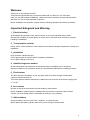
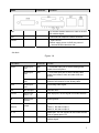
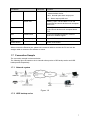
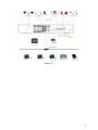
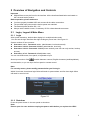
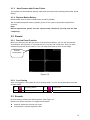
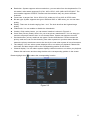
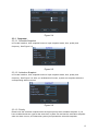
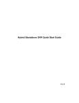
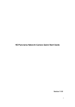
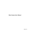
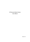
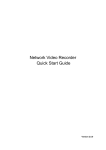
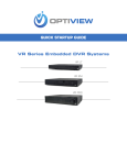
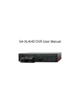
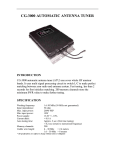
NVS Quick Start Guide Version 1.1.1 Table of Contents 1 2 3 4 Hardware Installation and Connection..........................................................................1 1.1 Check Unpacked NVS ..........................................................................................1 1.2 About Front Panel and Rear Panel.....................................................................1 1.3 After Remove the Chassis....................................................................................1 1.4 HDD Installation .....................................................................................................1 1.5 Front Panel .............................................................................................................2 1.5.1 SD backup series ........................................................................................2 1.5.2 HDD backup series .....................................................................................3 1.6 Rear Panel ..............................................................................................................4 1.6.1 SD backup series ........................................................................................4 1.6.2 HDD backup series .....................................................................................6 1.7 Connection Sample ...............................................................................................7 1.7.1 Network system ...........................................................................................7 1.7.2 HDD backup series .....................................................................................7 Overview of Navigation and Controls............................................................................9 2.1 Login, Logout & Main Menu .................................................................................9 2.1.1 Login..............................................................................................................9 2.1.2 Shutdown......................................................................................................9 2.1.3 Auto Resume after Power Failure ..........................................................10 2.1.4 Replace Button Battery ............................................................................10 2.2 Record ...................................................................................................................10 2.2.1 Preview Zoom Function............................................................................10 2.2.2 Live Viewing ...............................................................................................10 2.3 Encode ..................................................................................................................10 2.3.1 Snapshot.....................................................................................................12 2.4 Network .................................................................................................................13 2.5 Default ...................................................................................................................13 2.6 TV Adjust...............................................................................................................14 Web Operation................................................................................................................16 3.1 Network Connection ............................................................................................16 3.2 Login ......................................................................................................................16 3.3 Main Window ........................................................................................................16 Appendix Toxic or Hazardous Materials or Elements ..............................................18 i Welcome Thank you for purchasing our NVS! This quick start guide will help you become familiar with our NVS in a very short time. Here you can find hardware installation, cable connection information and general operations; also here you can find web operation instruction. Before installation and operation, please read the following safeguard and warning carefully! Important Safeguard and Warning 1.Electrical safety All installation and operation here should conform to your local electrical safety codes. We assume no liability or responsibility for all the fires or electrical shock caused by improper handling or installation. 2.Transportation security Heavy stress, violent vibration or water splash are not allowed during transportation, storage and installation. 3.Installation Keep upwards. Handle with care. Do not apply power to the NVS before completing installation. Do not place objects on the NVS 4.Qualified engineers needed All the examination and repair work should be done by the qualified service engineers. We are not liable for any problems caused by unauthorized modifications or attempted repair. 5.Environment The NVS should be installed in a cool, dry place away from direct sunlight, inflammable, explosive substances and etc. This series product shall be transported, installed and use under the environment ranging from o℃ to 55℃. 6. Accessories Be sure to use all the accessories recommended by manufacturer. Before installation, please open the package and check all the components are included: Contact your local retailer ASAP if something is missing in your package. 7. Lithium battery Improper battery use may result in fire, explosion, or personal injury! When replace the battery, please make sure you are using the same model! ii 1 Hardware Installation and Connection Note: All the installation and operations here should conform to your local electric safety rules. 1.1 Check Unpacked NVS When you receive the NVS from the forwarding agent, please check whether there is any visible damage. The protective materials used for the package of the NVS can protect most accidental clashes during transportation. Then you can open the box to check the accessories. Please check the items in accordance with the list. Finally you can remove the protective film of the NVS. Please note remote control is not our standard accessory and it is not included in the accessory bag. 1.2 About Front Panel and Rear Panel For detailed information of the function keys in the front panel and the ports in the rear panel, please refer to the User’s Manual included in the resource CD. The model in the front panel is very important; please check according to your purchase order. The label in the rear panel is very important too. Usually we need you to represent the serial number when we provide the service after sales. 1.3 After Remove the Chassis Please check the data cable, power cable, COM cable and main boar cable connection is firm or not. 1.4 HDD Installation This series NVS has only one SATA HDD. Please use HDD of 7200rpm or higher. You can refer to the User’s Manual for recommended HDD brand. Please follow the instructions below to install hard disk. 1. Loosen the screws of the 2. Fix four screws in the HDD 3. Place the HDD in accordance with upper cover and side panel. (Turn just three rounds). the four holes in the bottom. 1 4. Turn the device upside down 5. Fix the HDD firmly. and then turn the screws in 6. Connect the HDD cable and power cable. firmly. 7. Put the cover in accordance 8. Secure the screws in the with the clip and then place the rear panel and the side panel. upper cover back. Note: z You can connect the HDD data cable and the power cable first and then fix the HDD in the device. z Please pay attention to the front cover. It adopts the vertical sliding design. You need to push the clip first and then put down. 1.5 Front Panel 1.5.1 SD backup series Figure 1-1 Please refer to the following sheet for detailed information. 2 Icon ACT Name Color Power status indication light NET Wireless network status indication light ALM Alarm status indication light Video RS232 MIC Video transmission/ record status indication light 232 COM Red & green Green Red Blue debug Speaker: SPK Reset Reset z Power on: red. z In normal operation: green light on. z In upgrading: green light flickers. z Power off/disconnected: off. z Wireless internet in normal connection: on. z Wireless internet in unusual connection: off. z Armed: on. z Alarm data in transmission: flickers. z Disarmed: off. z Video in normal transmission: on. z In recording: flickers. z No video in transmission: off. To debug COMM, set IP and transmit transparent COM data. MIC SPK Function z Audio input port, active MIC analog audio signal input. z Input level: 100mV-5000mVp-p; input impendence: 10k ohms. z Audio input port, bidirectional talk analog signal output. z Output level: 2Vrms; Output impendence: 10k ohms. Back to factory mode after pressing the button for 3 seconds. IR Reserved 1.5.2 HDD backup series Figure 1-2 Please refer to the following sheet for detailed information. Icon Name Function Network status indication light Power status indication light HDD status indication light The red light becomes on when the network connection is not proper. The red light is on when the power connection is proper. The red light is on when the HDD malfunction occurred. 3 1.6 Rear Panel 1.6.1 SD backup series 1ch: Figure 1-3 Name Connector Function V-IN Video input port BNC Receive analog video signals from camera, dome and other front-end devices. V-OUT Video input port BNC Video output port. Output analog video signal. It can connect to the monitor to view analog video. A-IN Audio output port Input analog audio signal. SD SD card port Insert SD card. 1/2/3/4 Alarm Input Port 1~4 Alarm input port, receive signal from external alarm. G Ground Shared ground end NO/C-1 2ch alarm output z Output alarm signal to the alarm device. z NO/C-1: NO alarm output 1. z NO/C-2: NO alarm output 2 NO/C-2 A, B You can connect to the control devices such as speed dome PTZ. 4 Name Connector Function ANT To connect wireless antenna in order to receive 3G wireless signal. NET 10M/100M self-adaptive Ethernet interface. 12VDC z Input 12V DC z When supply power via PoE. the power of cameras shall be less than 3W. 2ch /4ch: Figure 1-4 Port Name AVIN Connector Function Audio input port BNC 1~4-ch audio input port to receive analog audio signals from microphone. Audio input port BNC 1~4-ch video input port to receive analog video signals from camera, dome and other front-end devices. Video input port BNC Video output port. Output analog video signal. It can connect to the monitor to view analog video. A-IN Audio input port Input analog audio signal. SD SD card port Insert SD card. 1/2/3/4 Alarm Input Port 1~4 Alarm input port, receive signal from external alarm. G Alarm input ground NO/C-1 2ch alarm output NO/C-2 Shared ground. z Output alarm signal to the alarm device. z NO/C-1: NO alarm output 1. z NO/C-2: NO alarm output 2 A、B RS485 port. You can connect to the control devices such as speed dome PTZ. ANT To connect wireless antenna in order to receive 3G wireless signal. 5 Port Name Connector Function NET 10M/100M self-adaptive Ethernet interface. 12VDC z Input 12V DC POE z When supply power via PoE. the power of cameras shall be less than 3W 1.6.2 HDD backup series Figure 1-5 Port Name AUDIO IN 1~4 Audio input port Connector Function BNC 1~4-ch audio input port to receive analog audio signals from microphone. The first channel audio input also used as the audio talk input port. VIDEO IN 1~4 Video input port BNC 1~4-ch video input port to receive analog video signals from camera, dome and other front-end devices. AUDIO OUT 1 Audio output port BNC Audio output port. Output analog audio signal to the devices such as sound box. VIDEO OUT 1 Video output port BNC Video output port. Output analog video signal. It can connect to the monitor to view analog video. Network Port 10M/100M self-adaptive Ethernet port. Connect to the network cable. USB Port Connect to USB mouse. VGA Video output port VGA 1~4 Alarm Input Port 1~4 I/O Port NO VGA video output port. Output analog video signal. It can connect to the monitor to view analog video. z Alarm input channel amount is 4 z When your alarm input device is using external power, please make sure the device and the NVS have the same ground. Ground end Alarm input ground end. Alarm Output z Output alarm signal to the alarm device. 6 Port Name C A Connector Port1 RS485 Port B ANT Function Please make sure there is power to the external alarm device. z NO:Normal open alarm output port. z C:Alarm output public end. RS485_A port. It is the cable A. You can connect to the control devices such as speed dome PTZ. RS485_B.It is the cable B. You can connect to the control devices such as speed dome PTZ. Antenna Port To connect wireless antenna in order to receive 3G wireless signal Power input port Input 12V DC Power Button Power on/off button. When connect the Ethernet port, please use crossover cable to connect the PC and use the straight cable to connect to the switcher or router. 1.7 Connection Sample The connection sample is shown as below. The following figure is based on the 4-channel series product of SD backup series and HDD backup series respectively. 1.7.1 Network system Figure 1-6 1.7.2 HDD backup series 7 Figure 1-7 8 2 Overview of Navigation and Controls Important z Slight difference may be found in the interface. All the interfaces listed below are based on the 4-channel series product. Before operation, please make sure: z You have properly installed HDD and connect all the cable connections. z The provided input power and the device power are matched. z The external power shall be DC +12V. z Always use the stable current, if necessary UPS is a best alternative measure. 2.1 Login, Logout & Main Menu 2.1.1 Login After system booted up, default video display is in multiple-window mode. You can see the login interface after right clicking any menu item. See Figure 2-1. System consists of four accounts: z z z Username: admin. Password: admin. (administrator, local and network) Username: 888888. Password: 888888. (administrator, local only) Username: 666666. Passwords: 666666(Lower authority user who can only monitor, backup and etc.) z Username: default. Password: default(hidden user) You can use USB mouse, front panel, or keyboard to input. About input method: Click to switch between numeral, English character (small/capitalized) and denotation; or you can input via front panel or remote control. Note: For security reason, please modify password after you first login. Within 30 minutes, three times login failure will result in system alarm and five times login failure will result in account lock! Figure 2-1 2.1.2 Shutdown Press the power button in the rear panel to shutdown. Note: Please open the case and then unplug the power cable before you replace the HDD! 9 2.1.3 Auto Resume after Power Failure The system can automatically backup video and resume previous working status after power failure. 2.1.4 Replace Button Battery Please make sure to use the same battery model if possible. We recommend replace battery regularly (such as one-year) to guarantee system time accuracy. Note: Before replacement, please save the system setup, otherwise, you may lose the data completely! 2.2 Record 2.2.1 Preview Zoom Function Move your mouse to the left top corner of the preview interface; you can see the preview zoom button. See Figure 2-2. Left click the icon; you can see a hook icon. Now you have enabled the preview zoom function. You can drag the mouse to zoom in the image. Preview zoom button Figure 2-2 2.2.2 Live Viewing After you logged in, the system is in live viewing mode. You can see system date, time and channel name. 1 Recording status 3 Video loss 2 Motion detection 4 Camera lock 2.3 Encode Encode setting includes the following items. See Figure 2-3. Please note some series do not support extra stream. z Channel: Select the channel you want. z Compression: System supports H.264. 10 z z z z z z z Resolution: System supports various resolutions, you can select from the dropdown list. For this model, main stream supports D1 (PAL: 25f/s. NTSC: 30f/s.)/HD1/2CIF/CIF/QCIF. The extra stream supports CIF/QCIF. Please note the resolution may vary due to different channels. Frame rate: It ranges from 1f/s to 25f/s in PAL mode and 1f/s to 30f/s in NTSC mode. Bit rate type: System supports two types: CBR and VBR. In VBR mode, you can set video quality. Quality: There are six levels ranging from 1 to 6. The sixth level has the highest image quality. Video/audio: You can enable or disable the video/audio. Overlay: Click overlay button, you can see an interface is shown in Figure 2-4. Cover area (Privacy mask): Here is for you to set privacy mask section. You can drag you mouse to set proper section size. In one channel video, system max supports 4 zones. Preview/monitor: privacy mask has two types. Preview and Monitor. Preview means the privacy mask zone can not be viewed by user when system is in preview status. Monitor means the privacy mask zone can not be view by the user when system is in monitor status. Time display: You can select system displays time or not when you playback. Please click set button and then drag the title to the corresponding position in the screen. Channel display: You can select system displays channel number or not when you playback. Please click set button and then drag the title to the corresponding position in the screen. Please highlight icon to select the corresponding function. Figure 2-3 11 Figure 2-4 2.3.1 Snapshot 2.3.1.1 Schedule Snapshot In Encode interface, click snapshot button to input snapshot mode, size, quality and frequency. See Figure 2-5. Figure 2-5 2.3.1.2 Activation Snapshot In Encode interface, click snapshot button to input snapshot mode, size, quality and frequency. See Figure 2-6. After you enabled this function, system can snapshot when the corresponding alarm occurred. Figure 2-6 2.3.1.3 Priority Please note the activation snapshot has the higher priority than schedule snapshot. If you have enabled these two types at the same time, system can activate the activation snapshot when an alarm occurs, and otherwise system just operates the schedule snapshot. 12 2.4 Network Here is for you to input network information. See Figure 2-7. z IP address: Here you can input IP address. z DHCP: It is to auto search IP. When enable DHCP function, you can not modify IP/Subnet mask /Gateway. These values are from DHCP function. If you have not enabled DHCP function, IP/Subnet mask/Gateway display as zero. You need to disable DHCP function to view current IP information. Besides, when PPPoE is operating, you can not modify IP/Subnet mask /Gateway. z TCP port: Default value is 37777. You can modify if necessary. z UDP port: Default value is 37778. You can modify if necessary. z HTTP port: Default value is 80. z Max connection: system support maximal 20 users. 0 means there is no connection limit. z Preferred DNS: DNS IP address. z Alternate DNS: DNS alternative IP address. z Transfer mode: Here you can select the priority between fluency/video qualities. z LAN download: System can process the downloaded data first if you enable this function. The download speed is 1.5X or 2.0X of the normal speed. z Advanced setting: Here you can set IP rights, NTP,multicast,PPPoE,DDNS,3G,email,FTP and alarm centre. Please refer to the user’s manual for detailed information. After completing all the setups please click save button, system goes back to the previous menu. Figure 2-7 2.5 Default 13 Click default icon, system pops up a dialogue box. You can highlight to restore default factory setup. See Figure 2-8. z Select all z General z Encode z Schedule z RS232 z Network z Alarm z Detect z Pan/tilt/zoom z Channel name Please highlight icon to select the corresponding function. After all the setups please click save button, system goes back to the previous menu. Warning! System menu color, date and time, user account will not maintain previous setup after default operation! Figure 2-8 2.6 TV Adjust Here is for you to adjust TV output setup. See Figure 2-9. Please drag slide bar to adjust each item. After all the setups please click OK button, system goes back to the previous menu. 14 Figure 2-9 15 3 Web Operation Important Slight difference may be found in the interface. All the interfaces listed below are based on the 4channel series product. 3.1 Network Connection Before web operation, please check the following items: z Network connection is right z NVS and PC network setup is right. Please refer to network setup(main menu->setting>network) z Use order ping ***.***.***.***(* NVS IP address) to check connection is OK or not. Usually the return TTL value should be less than 255. z System can automatically download latest web control and the new version can overwrite the previous one. z If you want to un-install the web controls, please run uninstall webrec2.0.bat to auto delete the control or you can go to C:\Program Files\webrec to delete Single folder. 3.2 Login Open IE and input NVS address in the address column. For example, if your NVS IP is 10.10.3.16, then please input http:// 10.10.3.16 in IE address column. System pops up warning information to ask you whether install webrec.cab control or not. Please click yes button. If you can’t download the ActiveX file, please modify your IE security setup. After installation, the interface is shown as below. See Figure 3-1. Please input your user name and password. Default factory name is admin and password is admin. Note: For security reasons, please modify your password after you first login. Figure 3-1 3.3 Main Window After you logged in, you can see the main window. See Figure 3-2. Click the channel name on the left side; you can view the real-time video. 16 For detailed operation information, please refer to the User’s Manual included in the resources CD. Figure 3-2 17 4 Appendix Toxic or Hazardous Materials or Elements Component Name Toxic or Hazardous Materials or Elements Pb Hg Cd Cr VI PBB PBDE ○ ○ ○ ○ ○ ○ ○ ○ ○ ○ ○ ○ Circuit Board ○ ○ ○ ○ ○ ○ Fastener Wire and Cable/ AC adapter Packing Material Accessories ○ ○ ○ ○ ○ ○ ○ ○ ○ ○ ○ ○ ○ ○ ○ ○ ○ ○ ○ ○ ○ ○ ○ ○ Sheet Metal(Case) Plastic Parts (Panel) Note O: Indicates that the concentration of the hazardous substance in all homogeneous materials in the parts is below the relevant threshold of the SJ/T11363-2006 standard. X: Indicates that the concentration of the hazardous substance of at least one of all homogeneous materials in the parts is above the relevant threshold of the SJ/T11363-2006 standard. During the environmental-friendly use period (EFUP) period, the toxic or hazardous substance or elements contained in products will not leak or mutate so that the use of these (substances or elements) will not result in any severe environmental pollution, any bodily injury or damage to any assets. The consumer is not authorized to process such kind of substances or elements, please return to the corresponding local authorities to process according to your local government statutes. Note z For detailed operation introduction, please refer to our resource CD included in your package for electronic version of the User’s Manual. z This quick start guide is for reference only. Slight difference may be found in the user interface. z All the designs and software here are subject to change without prior written notice. z All trademarks and registered trademarks mentioned are the properties of their respective owners. z If there is any uncertainty or controversy, please refer to the final explanation of us. z Please visit our website or contact your local service engineer for more information. 18