1
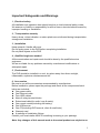
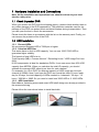
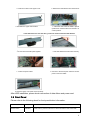
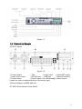
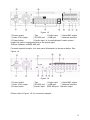
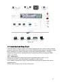
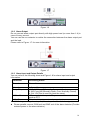
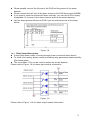
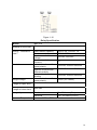
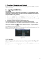
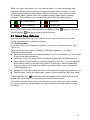
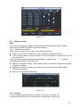
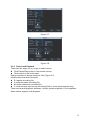
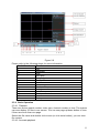
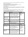
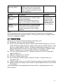
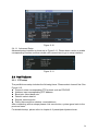
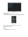
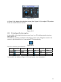
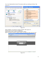
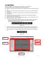
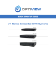
Standalone DVR Quick Start Guide 1 Table of Contents 1 Hardware Installation and Connections........................................................................7 1.1 Check Unpacked DVR ..........................................................................................7 1.2 HDD Installation .....................................................................................................7 1.2.1 Choose HDDs ..............................................................................................7 1.2.2 Calculate HDD Size ....................................................................................7 1.2.3 HDD Installation...........................................................................................7 1.3 Front Panel .............................................................................................................8 1.4 Rear Panel ............................................................................................................10 1.5 Connection Sample .............................................................................................11 1.6 Alarm Input and Relay Output ...........................................................................13 1.6.1 1.6.2 1.6.3 1.6.4 2 Alarm Input .................................................................................................13 Alarm Output ..............................................................................................14 Alarm Input and Output Details...............................................................14 Relay Output Description .........................................................................15 Overview of Navigation and Controls..........................................................................17 2.1 Login, Logout & Main Menu ...............................................................................17 2.1.1 2.1.2 2.1.3 2.1.4 2.1.5 Login............................................................................................................17 Main Menu..................................................................................................17 Logout .........................................................................................................18 Auto Resume after Power Failure ..........................................................18 Replace Button Battery ............................................................................18 2.2 Recording Operation ...........................................................................................18 2.2.1 Live Viewing ...............................................................................................18 2.3 Record Setup (Schedule) ...................................................................................19 4.4.1 Schedule Menu ............................................................................................19 2.3.1 Manual record ............................................................................................20 2.3.2 Encode ........................................................................................................20 2.3.3 Search and Playback................................................................................22 2.3.4 Basic Operation .........................................................................................23 2.4 Network Setup......................................................................................................25 2.5 Pan/Tilt/Zoom .......................................................................................................26 2 2.5.1 PTZ setup ...................................................................................................26 2.5.2 PTZ operation ............................................................................................27 2.5.3 3D Intelligent Positioning Key .................................................................28 3 Web Client Operation ....................................................................................................29 3.1 Network Connection ............................................................................................29 3.2 Login ......................................................................................................................29 3.3 Main Window ........................................................................................................31 3 Welcome Thank you for purchasing our DVR! This quick start guide will help you become familiar with our DVR in a very short time. Here you can find hardware installation, cable connection information and general operations such as system setup, record, search, backup, alarm setup, PTZ operation, also here you can find web operation instruction. Before installation and operation please read the following safeguards and warnings carefully! 4 Important Safeguards and Warnings 1.Electrical safety All installation and operation here should conform to local electrical safety codes. We assume no liability or responsibility for all the fires or electrical shock caused by improper handling or installation. 2.Transportation security Heavy stress, violent vibration or water splash are not allowed during transportation, storage and installation. 3.Installation Keep upwards. Handle with care. Do not apply power to the DVR before completing installation. Do not place objects on the DVR 4.Qualified engineers needed All the examination and repair work should be done by the qualified service engineers. We are not liable for any problems caused by unauthorized modifications or attempted repair. 5.Environment The DVR should be installed in a cool, dry place away from direct sunlight, inflammable, explosive substances and etc. 6. Accessories Be sure to use all the accessories recommended by manufacturer. Before installation, please open the package and check all the components listed below are included: z One power cable z One Ethernet cable z Four HDD cables z Alarm & relay terminal blocks z Extensional cable(for audio, loop & matrix) z One remote control(including the battery) z One USB mouse z One CD(including DVR manual, client & small tools) z Warranty card z A package of installation fittings Contact your local retailer ASAP if something is missing in your package. Note: Any changes of this manual made to the actual product are subject to no 5 further notification. 6 1 Hardware Installation and Connections Note: All the installation and operations here should conform to your local electric safety rules. 1.1 Check Unpacked DVR When you receive the DVR from the shipping agency, please check whether there is any visible damage to the DVR appearance. The protective materials used for the package of the DVR can protect most accidental clashes during transportation. Then you can open the box to check the accessories. Please check the items in accordance with the list on the warranty card. Finally you can remove the protective film of the DVR. 1.2 HDD Installation 1.2.1 Choose HDDs We recommend Seagate HDD of 7200rpm or higher. 1.2.2 Calculate HDD Size This series have no limit to HDD capacity. You can use 120G-750G HDD to guarantee higher stability. The formula of total HDD size is: Total Capacity (MB) = Camera Amount * Recording Hours * HDD Usage Per Hour (M/h) H.264 compression is ideal for standalone DVRs. It can save more than 30% HDD capacity than MPEG4. When you calculate the total HD capacity, you should estimate the average HDD capacity per hour for each channel. For example, for a 4-ch DVR, the average capacity of HDD usage per hour per channel is 200M/h. Now if you hope the DVR can record the video 12 hours each day for 30 days, the total capacity of HDDs needed is: 4 channels * 30 days * 12 hours * 200 M/h = 288G. So you need to install one 300G HDD or 2 160G HDDs. 1.2.3 HDD Installation Data ribbons, fastening screws and smart HDD shelf design are already provided in the accessories bag. Please follow the instructions below to install hard disk. 2 7 1. Loosen the screws of the upper cover. 3. Dismantle the upper HDD bracket. 2. Remove the HDD bracket from internal unit. 4. Install the HDD. Note the HDD is placed upside down. Please make sure bracket is in correct position. If the HDD amount is less than four, you do not need to install the HDD bracket. 5. Screw the two bracket parts together. 6. Put HDD bracket back and then fix firmly. 8 7. Loosen the power cable. 8. Connect to the SATA ports and then connect power cord to the HDDs. 9. Place the upper cover back and screw firmly. After HDD installation, please check connection of data ribbon and power cord. 1.3 Front Panel Please refer to the following sheet for front panel button information. Name Icon Function Power button POWER Power button, press this button for three seconds to shut down DVR. 8 Power indication light Power indication light In preview interface(no other menu), press this button for three seconds, y can switch between TV/VGA output(HD1 series DVR has three modes TV/VGA/60Hz LCD) Shift In textbox, click this button to switch between numeral, English(Small/Capitalized),donation, Chinese and etc. Open/close tour numeral keys 0-9 0-9 Input password, switch channel and input numeral. When you need to input numeral more than 9. You can follow the steps below, click the first key number and then the next. For example, input 123, click numeral 1 and then 2 and click 3(continuously). Input numeral more than10 Activate current control, modify setup, increase/decrease numeral, assistant function such as PTZ menu. Up/down S、T Left/right W、X shift current activated control, When playback, click these buttons to control playback bar. ESC ESC Close upper interface or controls. confirm operation Enter ENTER Go to default button Go to main menu Record ● Slow play Manually stop/start recording, working with direction keys or numeral keys, Multiple slow play speeds or normal playback One-window monitor mode, click this button to display assistant function: PTZ control and image color. In PTZ menu, shift PTZ control menu. Backspace function: in numeral control or text control, it can delete the previous character before the cursor. Assistant Fn In motion detection setup, working with Fn and direction keys to realize setup. In HDD information menu, switch between HDD record time or other information(Menu prompt) Realize other special functions Fast play Various fast speeds and normal playback. _ Play previous In playback mode, playback the previous video In menu setup, go to upper ward of the dropdown list. 9 Reverse/Pause W In normal playback or pause mode, click this button to reverse playback In reverse playback, click this button to pause playback. f In playback mode, playback the next video In menu setup, go to down ward of the dropdown list. Play Next Play/Pause f Reverse playback or paused mode, click this button to realize normal playback In normal playback click this button to pause playback In pause mode, click this button to resume playback In real-time monitor mode, click this button to enter video search menu. USB port To connect USB storage device, USB mouse or USB CD-ROM Channel indication light When DVR is recording this lamp turns on. Standby indication light When DVR is standing by, this lamp turns on. Remote control signal receiver To receive signals from remote control Function indication light Window switch MULT Switch between one-window and multiple-window display modes. confirm current operation Enter ENTER go to default button Go to main menu Cancel ESC Shuttle(outer ring) Jog(inner dial) Close upper interface or controls. In real-time monitor mode it works as left/right direction key. Playback mode, counter clockwise to forward and clock wise to backward Up/down direction key. Playback mode, turn the inner dial to realized frame by frame playback. (only applies to some version.) 1.4 Rear Panel Please refer to Figure 1-1for real panel information. Please note all the operation and instruction in this quick start guide is taking 16-ch DVR as an example. 10 Figure 1-1 1.5 Connection Sample CIF/2CIF Model Figure 1-2 ①Power socket ②Fan ③Video input ④Video BNC output ⑤Video VGA output ⑥RS-232 port ⑦USB port ⑧Network interface ⑨Power button ⑩Audio input/ 4 ch audio&loop&1 matrix output/ loop&4 ch matrix output(according to the actual type) ⑪Alarm in&alarm out&RS-485 port D1 SATA Dual Network Ports Model 11 Figure 1-3 ①Power socket ②Fan ③Video input ④Video BNC output ⑤Video VGA output ⑥RS-232 port ⑦USB port ⑧Network interface ⑨Power button ⑩Audio input / 4 ch audio&loop&1 matrix output / loop&4 ch matrix output(according to the actual type) ⑪Alarm in&alarm out&RS-485 port For some special models, 4-ch rear panel information is shown as below. See Figure 1-4. Figure 1-4 ①Power socket ⑤Video VGA output ⑨Power button ②Fan ③Video input ④Video BNC output ⑥RS-232 port ⑦USB port ⑧Network interface ⑩Audio input ⑪RS-485 port ⑫Audio output Please refer to Figure 1-5 for connection sample. 12 Figure 1-5 1.6 Alarm Input and Relay Output The DVR offers 16 alarm inputs for external signaling devices, such as door contacts or motion detectors. Each alarm input can be either normally open or normally closed. Once configured, an alarm input can invoke many different activities, including triggering a relay device, sending an alert to a security office or storing pre-alarm video to the DVR. 1.6.1 Alarm Input You should check your alarm input mode is grounding alarm input or not. For this series DVR, grounding signal is needed for alarm input. If you need to connect two units or one DVR and other device, please use relay to separate them. Please refer to Figure 1-6 for more information. 13 Figure 1-6 1.6.2 Alarm Output Do not connect alarm output port directly with high power load (no more than 1 A) in case of heavy current. You can use the co-contactor to realize the connection between the alarm output port and the load. Please refer to Figure 1-7 for more information. Figure 1-7 1.6.3 Alarm Input and Output Details You can refer to the following sheet and Figure 1-8 for alarm input and output information. Parameter Grounding Alarm Ground Ground line Alarm Input Relay Output 1, 2, …, 16 1,2,3,4: NO and C(Normally Open and Com) 5: NO,C and NC(Normally Open, Com, Normally Closed) 6: Ctrl 12V(This is used for reset the senor) 485 communication port. They are used to control devic 485 A、B such as PTZ. This should input an external power input. +12(C) z 4/8/16-ch grounding alarm inputs. (Normal open or Normal close type) z Please parallel connect COM end and GND end of the alarm detector (Provide external power to the alarm detector). 14 z z z z Please parallel connect the Ground of the DVR and the ground of the alarm detector. Please connect the NC port of the alarm sensor to the DVR alarm input(ALARM) If you need to reset the touched-off alarm remotely, you can use DVR to supply controllable 12 V power to the alarm detector such as the smoke detector. Use the same ground with that of DVR if you use external power to the alarm device. Figure 1-8 1.6.4 Relay Output Description z 6 ways relay alarm output. Provide external power to external alarm device. z To avoid over loading, please read the following relay parameters sheet carefully. (See below table) z The controllable +12v can be used to restore the smoke detector. Please refer to Figure 1-9 for alarm input module information. Figure 1-9 Please refer to Figure 1-10 for alarm output module information. 15 Figure 1-10 Model: Material of the touch Rating(resistance load) Insulation Surge voltage Length of open time Length of close time Longevity Relay Specification JRC-27F Silver Rated switch capacity Maximum switch power Maximum switch voltage Maximum switch currency between touches with same polarity between touches with different polarity between touch and winding between touches with same polarity 3ms max 30VDC 2A, 125VAC 1A 125VA 160W 250VAC, 220VDC 1A 1000VAC 1minute 50/60Hz 1000VAC 1minute 50/60Hz 1000VAC 1minute 50/60Hz 1500V (10×160us) 3ms max Mechanical Electrical Temperature -40℃ ~+70℃ 50×106 times (3Hz) 200×103 times (0.5Hz) 16 2 Overview of Navigation and Controls Before operation, please make sure you have properly installed HDDs and all the cable connections. 2.1 Login, Logout & Main Menu 2.1.1 Login When the system boots up, default video display is in multiple-window mode. Click Enter or left click mouse, you can see the login interface. See Figure 2-1. System consists of four accounts: z Username: admin. Password: admin. (administrator, local and network) z Username: 888888. Password: 888888. (administrator, local only) z Username: 666666. Passwords: 666666(Lower authority user who can only monitor, playback, backup and etc.) z Username: default. Password: default(hidden user) For your system security, please modify you password after first login. You can use USB mouse, front panel, remote controller or keyboard to input. About input method: Click to switch between numeral, English character (small/capitalized) and denotation. Note: Three times login failure in 30 minutes will result in system alarm and five times login failure will result in account lock! Figure 2-1 2.1.2 Main Menu After you logged in, the system main menu is shown as below. See Figure 2-2. There are total six icons: search, information, setting, backup, advanced and shutdown. You can move the cursor to highlight the icon, and then left click mouse to enter the sub-menu. 17 Figure 2-2 2.1.3 Logout There are two ways for you to log out. One is from menu option: In the main menu, click shutdown button, you can see an interface is shown as below. See Figure 2-3. Figure 2-3 There are several options for you. See Figure 2-4. Figure 2-4 The other ways is to press power button on the front panel for at least 3 seconds, system will stop all operations. Then you can click the power button in the rear panel to turn off the DVR. 2.1.4 Auto Resume after Power Failure The system can automatically backup video and resume previous working status after power failure. 2.1.5 Replace Button Battery Please make sure to use the same battery model if possible. We recommend replace battery regularly (such as one-year) to guarantee system time accuracy. 2.2 Recording Operation 2.2.1 Live Viewing 18 When you login, the system is in live viewing mode. You can see system date, time and channel name. If you want to change system date and time, you can refer to general settings (Main Menu->Setting->General). If you want to modify the channel name, please refer to the display settings (Main Menu->Setting>Display). The following icons stand for camera's video and alarm status. 1 Recording status 3 Video loss 2 Motion detection 4 Camera lock Note: Please refer to the following sheet for channel status. switch function, stands for opening stands for closing switch function. 2.3 Record Setup (Schedule) When the system boots up, it is in default 24-hour regular mode. You can set record type and time in schedule interface. 4.4.1 Schedule Menu In the main menu, from setting to schedule, you can go to schedule menu. See Figure 2-5. There are three record types: R-Regular, MD-Motion detection, A- Alarm. There are total six periods. z Channel: Please select the channel number first. You can select “all” if you want to set for the whole channels. z Week day: There are eight options: ranges from Saturday to Sunday and all. z Redundancy: System supports redundancy backup function. You can highlight Redundancy button to activate this function. Please note, before enable this function, please set at least one HDD as redundant.(Main menu->Advanced>HDD Management) z Snapshoot: You can enable this function to snapshoot image when alarm occurs. z Record types: There are three types: regular, motion detection (MD) and Alarm. to select the corresponding function. After all the setups Please highlight icon please click save button, system goes back to the previous menu. At the bottom of the menu, there are color bars for your reference. Green stands for regular recording, yellow stands for motion detection and red stands for alarm recording. 19 Figure 2-5 2.3.1 Manual record Note: You need to have proper rights to implement the following operations. Please make sure the HDDs have been properly installed. 2.3.1.1 Manual record menu There are two ways for you to go to manual record menu. z Right click mouse or in the main menu, Advanced->Manual Record. z In live viewing mode, click record button in the front panel or record button in the remote control. There are three statuses: schedule/manual/stop. Highlight icon“○” to select corresponding channel. See Figure 2-6. z Manual: the highest priority. After manual setup, all selected channels will begin ordinary recording. z Schedule: channel records as you have set in recording setup (Main Menu>Setting->Schedule) z Stop: all channels stop recording. Figure 2-6 2.3.2 Encode For one stream series DVR, the interface is shown as in Figure 2-7. For dual-stream series DVR, the interface is shown as in Figure 2-8. 20 Channel: Select the channel you want. Compression: system supports H.264. Or you can select from the dropdown list. Resolution: System supports various resolutions, you can select from the dropdown list. For this model, we can support D1/CIF. z Bit rate: system supports two types: CBR and VBR. In VBR mode, you can set video quality. z Quality: There are six levels ranging from 1 to 6. The sixth level has the highest image quality. z Frame rate: there are six levels: 1 f/s,2f/s,3f/s, 6f/s,12f/s,25f/s. (Some series DVRs only support PAL 25f/s ) z Video/audio: you can enable or disable the video/audio. z Overlay: click overlay button, you can see an interface containing the following items. Cover area (Privacy mask): Here is for you to set window blanking section. You can drag you mouse to set proper section size. Preview/monitor: privacy mask has two types. Preview means the privacy mask zone can not be viewed by user when system is in preview status. Monitor means the privacy mask zone can not be view by the user when system is in monitor status. Time display: You can select system displays time or not when you playback. Channel display: You can select system displays channel number or not when you playback. z Snapshoot: Click snapshoot button, you can see an interface containing the following items.(This function applies to some series only) Mode: There are two types: one is timing and the other is activation (trigger). Image size: D1/HD1/BCIF/CIF. Image quality: level1 to level 6. Snapshoot frequency: Here you can set the snapshoot frequency. The value ranges from 1s/p to 7s/p. System default setup is: z Channel:1 z Compression:H.264 z Resolution: CIF/D1 z Bit rate: CBR z Quality: 4 z Frame rate: 25f/s z z z Please highlight icon to select the corresponding function. 21 Figure 2-7 Figure 2-8 2.3.3 Search and Playback There are two ways for you to go to search menu. z Click Pause/Play button in the remote control. z Click search in the main menu. Search interface is shown as below. See Figure 2-9. Usually there are three file types: z R: regular recording file. z A: external alarm recording file. z M: motion detection recording file z C: card and pos test overlay recording file(For some special series only) There are several playback windows. Usually system supports 1/2-ch playback. Some series support 4-ch playback. 22 Figure 2-9 Please refer to the following sheet for more information. Serial Number Function 1 Play 2 Backward 3 Stop 4 Slow play 5 Fast play 6 Previous frame 7 Next frame 8 Volume 9 Previous file 10 Next channel 11 Next file 12 Previous channel 13 Search 14 Backup 2.3.4 Basic Operation 2.3.4.1 Playback There are various search modes: video type, channel number or time. The system can max display 32 files in one screen. You can use page up/down button to view if there are more than one page. Select the file name and double click mouse (or click enter button), you can view file content. 2.3.4.2 Accurate playback 23 Input time (h/m/s) in the time column and then click playback button, system can operate accurate playback. 2.3.4.3 Synchronized playback function when playback During playback process, click numeral key, system can switch to the corresponding channel video of the same time. 2.3.4.4 Digital zoom When the system is in full-screen playback mode, drag your mouse in the screen to select a section and then left click mouse to realize digital zoom. You can right click mouse to exit. 2.3.4.5 File backup System supports backup operation during search. You can draw a √ before file name (multiple choices). Then click backup button (Button 14 in Figure 2-9). 2.3.4.6 Slow playback and fast playback Please refer to the following sheet for slow play and fast playback function. Button Illustration Remarks Fast play button In playback mode, click this button to Frame rate may switch between various fast play vary due to modes such as fast play 1,fast play different 2 and more.(Fast play 1 means fast versions. play level 1 or not about speed) Slow play button ► (Or you can turn the outer ring counter clockwise.) In playback mode, click this button to switch between various slow play modes such as slow play 1 or slow play 2. In slow playback mode, click this button to switch between play/pause modes. In playback mode, you can click _ 4、Previous/next and ` to view previous or next video in current channel. 2.3.4.7 Fast forward/fast backward and frame by frame playback Special Functions Illustration Remarks of Shuttle and Jog Fast forward(outer When playback, turn the shuttle In forward or ring clockwise) (outer ring) clockwise one round: backward mode, you can view in fast level 1 double click Turn it two rounds you get fast Pause/Play button level 2. You can continue turning to get normal to get different speed. playback. 3、Play/Pause► Fast backward(outer ring counter clockwise) When playback, turn the shuttle (outer ring) counter clock-wise one round, you can view in backward level 1. Turn it two rounds, you get backward level 2. You can continue turning to get different speed. Frame rate may vary due to different version. 24 Manual playback frame by frame In playback mode, click play/pause button, slowly turn the jog (inner dial) clock-wise to view frame by frame, counter clock wise to view I frame playback. 2.3.4.8 Backward playback and frame by frame playback Button Illustration Backward play In normal playback mode, left click _ in playback backward play button, system begins interface. backward playback. Double click backward play button again, system goes to pause mode. Manual playback frame by frame. Click pause button in normal playback mode, slowly turn the jog (inner dial) clock-wise to view frame by frame, counter clock wise to view I frame playback. Remarks When system is in backward play or frame by frame playback mode, you can click play button to go to normal playback. Note: All the operations here (such as playback speed, channel, time and progress) have relationship with hardware version. Some series DVRs do not support some functions or playback speeds. 2.4 Network Setup Here is for you to input network information. See Figure 2-10. z IP address: Here you can input IP address. z DHCP: It is auto search IP function. When enable DHCP function, you can not modify IP/Subnet mask /Gateway. These values are from DHCP function. If you have not enabled DHCP function, IP/Subnet mask/Gateway display as o. You need to disable DHCP function to view current IP information. Besides, when PPPoE is operating, you can not modify IP/Subnet mask /Gateway. z TCP port: Default value is 37777. (System server port 37778 is reserved for network UDP use.) z UDP port: Default value is 37778. z HTTP port: Default value is 80. z Max connection: system support maximal 10 users. 0 means there is no connection limit. z Transfer mode: Here you can select the priority between fluency/video qualities. z Network download: System can process the downloaded data first if you enable this function. After completing all the setups please click save button, system goes back to the previous menu. 25 Figure 2-10 2.4.1.1 Advanced Setup Advanced setup interface is shown as in Figure 2-11. Please draw a circle to enable corresponding function and then double click current item to go to setup interface. Figure 2-11 2.5 Pan/Tilt/Zoom 2.5.1 PTZ setup The pan/tilt/zoom setup includes the following items. Please select channel first. See Figure 2-12. z Protocol: select corresponding PTZ protocol such as PELCOD. z Address: input corresponding PTZ address. z Baud rate: select baud rate. z Data bit: select data bit. z Stop bit: select stop bit. z Parity: there are three choices: none/odd/even. After completing all the setups please click save button, system goes back to the previous menu. For detailed setup, please refer to chapter 4.9 preset/patrol/pattern/scan. 26 Figure 2-12 After completing all the setups please click save button. 2.5.2 PTZ operation In one window display mode, right click mouse (click “Fn” Button in the front panel or click “Fn” key in the remote control). The interface is shown as in Figure 2-13. Figure 2-13 Click Pan/Tilt/Zoom, the interface is shown as below. See Figure 2-14. Here you can set the following items: z Step: value ranges fro 1 to 8. z Zoom z Focus z Iris Click icon and to adjust zoom, focus and iris. 27 Figure 2-14 In Figure 2-14, please click direction arrows (See Figure 2-15) to adjust PTZ position. There are total 8 direction arrows. Figure 2-15 2.5.3 3D Intelligent Positioning Key In the middle of the eight direction arrows, there is a 3D intelligent positioning key. See Figure 2-16. Click this key, system goes back to the single screen mode. Drag the mouse in the screen to adjust section size. It can realize PTZ automatically. Figure 2-16 Here is a sheet for you reference. Name Function function key Near Zoom Focus Near close Iris Shortcut key ► _ W Function key function Shortcut Key Far Far Open ► f You can click set button in Figure 2-14 to set preset, tour, and pattern. 28 3 Web Client Operation There might be slightly difference in the interface due to different series. 3.1 Network Connection Before web client operation, please check the following items: z Network connection is right z DVR and PC network setup is right. Please refer to network setup(main menu>setting->network) z Use order ping ***.***.***.***(* DVR IP address) to check connection is OK or not. Usually the return TTL value should be less than 255. z System is compatible with WIN VISTA web control right now. But you need to disable user account control function. Double click user account and then disable user account control. After completing setup, please reboot the PC. z System can automatically download latest web control and the new version can overwrite the previous one. z If you want to un-install the web control, please go to start and then click run button, input regsvr32 -u WebRec.ocx in the pop up dialogue box or run uninstall web.bat to un-install. Please note, before you un-install, please close all web page, otherwise the un-installation might result in error. 3.2 Login Open IE and input DVR address in the address column. For example, if your DVR IP is 10.10.3.16, then please input http:// 10.10.3.16 in IE address column. See Figure 3-1 Input your IP address here. Figure 3-1 System pops up warning information to ask you whether install webrec.cab control or not. Please click yes button. 29 If you can’t download the ActiveX file, please modify your settings as follows. See Figure 3-2. Figure 3-2 After installation, the interface is shown as below. See Figure 3-3. Please input your user name and password. Default factory name is admin and password is admin. Note: For security reasons, please modify your password after you first login. Figure 3-3 30 3.3 Main Window After you logged in, you can see the main window. See Figure 3-6. This main window can be divided into the following sections. z Section 1: there are five function buttons: configuration, search, alarm, about, log out. z Section 2: there are channel number and two function buttons: start dialog and local play. z Section3: there are PTZ, color button and you can also select picture path and record path. z Section 4:real-time monitor window. Please note current preview window is circled by a green rectangle zone. z Section 5: Here you can view window switch button. You can also select video priority between fluency or real-time. System monitor window switch supports full screen/1-window/4-window/6window/8-window/9-window/13-window/16-window/20-window/25window/36-window. See Figure 3-4. Figure 3-4 Preview window switch. System support 1/4/8/9/16-window real-time preview. Please you need to have the proper rights to implement preview operation. You can not preview if you have no right to preview the either channel. See Figure 3-5. Figure 3-5 Section1 Section 3 Section 2 Section 4 Section 5 31 Figure 3-6 Note For security reason, only the user of high-level can shut down the DVR. Do remember logging out the system in case there is vicious operation under your name! For detailed operation introduction, please refer to our resource CD included in your package for electronic version of the user’s manual. Slight difference may be found in user interface. All the designs and software here are subject to change without prior written notice. Please visit our website for more information. 32