1
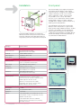
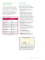
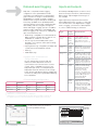
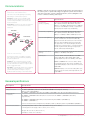
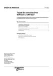
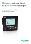
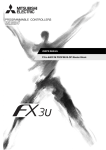
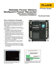
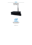
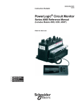
Advanced power quality analysis
coupled with revenue accuracy
in a web compatible meter
PowerLogic® ION7550/ION7650 series
Energy and power meters
Industry
PowerLogic
ION7550/7650
series power and energy meters
Used at key distribution points and sensitive loads, the PowerLogic ION7550 and ION7650
series meters offer unmatched functionality, including advanced power quality analysis
coupled with revenue accuracy, multiple communications options, web compatibility and
control capabilities.
Integrate these meters with our PowerLogic ION Enterprise® software, or share operations
data with existing SCADA systems, through multiple communication channels and protocols.
Typical applications
For infrastructure, industrials and buildings
For electric utilities
•Energy savings
>>Measure efficiency, reveal opportunities
and verify savings
>>Reduce peak demand surcharges
>>Reduce power factor penalties
>>Strengthen rate negotiation with energy suppliers
>>Enable participation in load curtailment
programs (e.g., demand response)
>>Identify billing discrepancies
>>Leverage existing infrastructure capacity
and avoid over-building
>>Support proactive maintenance to prolong
asset life
•Energy availability and reliability
>>Improve T&D network reliability
>>Enhance substation automation to reduce field service time
>>Maximize the use of existing infrastructure
•Energy availability and reliability
>>Validate that power quality complies with the energy contract
>>Verify the reliable operation of equipment
>>Improve response to power quality-related problems
2 • ION7550/7650 series power and energy meters
•Revenue metering and power quality
>>Install new high-accuracy metering at all
interchange points
>>Improve or verify metering accuracy at existing interchange points
>>Verify compliance with new power quality standards
>>Analyze and isolate the source of power
quality problems
Features
> High visibility, multilingual,
IEC/IEEE configureable display
Large, backlit LCD presents multiple simultaneous
real-time and time-stamped historical parameters,
as well as graphical trends and histograms.
> High accuracy standards
Meets stringent IEC and ANSI measurement
accuracy standards, such as IEC 62053-22 Class 0.2S, ANSI C12.20 0.2 Class 10 and 20.
> Digital fault-recording
Simultaneously capture voltage and current
channels for sub-cycle disturbance transients, as well as multi-cycle sags/swells and outages:
1024 samples/cycle waveform recording, 20/17 μs transient capture (50/60 Hz).
> Power quality analysis and
compliance monitoring
A choice of THD metering, individual current
and voltage harmonics readings, waveform
capture, EN50160 and flicker (PowerLogic
ION7650 only) power quality compliance
evaluation and voltage and current disturbance
(sag/swell) detection. COMTRADE format
waveform records are now available only for
meters with the Ethernet port option.
> Complete communications:
Ethernet (RJ 45 modular or SC fiber) –
Serial (RS 485 and/or RS 232) – Modem
Gateway functionality simplifies communications
architecture and reduces leased line or
connection costs. Concurrent, independent ports
communicate with protocols such as ION, DNP
3.0, IEC 61850, Modbus RTU, Modbus TCP,
Modbus Master. Ethernet port allows the following
concurrent connections: 24 Modbus, 8 generic
(ION / DNP / Modbus), 4 IEC 61850 dedicated
client, 1 FTP and 1 SNMP. Dial-out capability
when memory is near full. Data push capability
through SMTP (email).
> Patented ION technology
Provides a modular, flexible architecture that
offers extensive user programmability. Uniquely
addresses complex monitoring and control
applications. Adapts to changing needs, avoiding obsolescence.
> Disturbance direction detection
Determine the location of a disturbance more
quickly and accurately by determining the direction
of the disturbance relative to the meter. Analysis
results are captured in the event log, along with a time-stamp and confidence level indicating level
of certainty.
> Alarm setpoint learning
Helps simplify alarming configurations by
monitoring normal operating parameters and,
over time, learning what constitutes a sag, swell,
transient or high and low setpoint. Learning can
be configured in either ION Setup™ or PowerLogic
ION Enterprise software.
> Trending and forecasting
Forecast values, such as demand to better control
demand charges and billing rates. View results via
the meter’s web pages. Analyse trends to support
proactive maintenance schedules.
> Transformer/line loss compensation
Automatically measure, compensate and correct
for transformer or line losses when meter is
physically separated from the point of billing or
change of ownership.
> Inputs and outputs
Digital and analog inputs and outputs for pulse
counting, demand metering for other WAGES
utilities, equipment status/position monitoring,
demand synchronization, triggering conditional
energy metering, equipment control or interfacing.
ION7550/7650 series power and energy meters • 3
Installation
Front panel
Use for both display and configuration purposes.
The large backlit LCD display screen and the
numerous selection, navigation and configuration
softkeys allow quick, secure access to basic
meter configuration screens. The front panel
also provides access to many other meter
functions, such as meter resets and has multiple
programmable screens for numeric and timestamped values, frequency spectrum (harmonics),
trend logs and name plate data.
Designed to fit DIN standard 192 cutout (186 mm by
186 mm). Circuit and control power connections include
4-Wire Wye, 3-Wire Wye, 3-Wire Delta, Direct Delta and
single-phase systems. four voltage and five current inputs.
Input(s)
The large display automatically scrolls through
displays screens that present at-a-glance Volts,
Amps, power, energy and demand values. Screens
are easily customized to suit user requirements.
Set parameter measurements via front panel to
comply with regional preferences. Modbus Master
feature allows display of real-time parameters of
any downstream modbus devices.
Specifications
Voltage inputs
Nominal full scale
347 Vac direct line-to-neutral, 600 Vac direct line-to-line, RMS
Overload
1500 Vac RMS continuous
Input impedance
5 MΩ/phase (phase-Vref)
Fault capture
1200 V peak
Phasors display
Current inputs
Nominal current
5 A, 10 A and/or 20 A (1 A, 2 A, 5 A optional current range)
Max. voltage
600 V RMS (CAT III IEC 61010-1)
Withstand
2500 Vac, 60 Hz for 1 min
Load/burden
0.05 VA/phase (at 5 A standard)
0.015 VA/phase (at 1 A optional)
Impedance
0.002 Ω/phase (phase-Vref)
0.015 Ω (optional current range)
Energy received/delivered display
Control power
Operating range
Standard: AC: 85 Vac to 240 Vac (±10%),
47 Hz to 63 Hz; DC: 110 Vdc to 300 Vdc (±10%)
Burden: Typical 15 VA, max. 35 VA
Optional: low voltage DC power supply
Rated inputs: DC: 20 Vdc to 60 Vdc (±10%)
Burden: Typical 12 VA, max. 18 VA
Current probes with AC voltage output
Rated inputs
1 V RMS
Overload
5.5 V (CAT I IEC 61010-1)
Impedance
220 kΩ max.
Options
Current probe inputs for use with 0 Vac to 1 Vac
current probes. Probes sold separately. Accuracy
depends on probe specs.
Current probe inputs with three calibrated Universal Technic 10 A clamp-on CTs, meeting IEC 61036 accuracy.
4 • ION7550/7650 series power and energy meters
Harmonic current display
Trend display
Power and energy
measurements
High-accuracy four-quadrant energy metering in
accordance with IEC 62053-22 Class 0,2S for
both 3- and 2-element systems. Real, bidirectional,
reactive and apparent values. Fully programmable
integrating period (1, 5, 10, 15, 30, 60 min or other).
Supports block, rolling block and predicted
demand calculations such as: kW, kVAr and kVA
demand, min./max.; Volts and Amps demand,
min./max.; cumulative demand; demand on any
instantaneous measurement.
Measurement specifications[1]
[1]
[2]
Parameter
Accuracy ±
(% reading)
Voltage (line-line, line-neutral): per phase,
min./max., unbalance
0.1%
Frequency: present, min./max.
±0.005 Hz
Current (I1, I2, I3)
0.1%
Current (I4, I5)
0.4%
Power: real (kW), reactive
(kVAr), apparent (kVA), per-phase, total
IEC 62053-22 Class 0,2S[2]
Energy: real (kWh), reactive (kVArh), apparent (kVAh), in/out
IEC 62053-22 Class 0,2S[2]
kWA, kVA demand
calculations
IEC 62053-22 Class 0,2S[2]
Power factor (at Unity PF)
0.2%
Refer to user’s manual for valid measurement ranges
Refer to compliance section. Not applicable for NICT meters,
contact factory for measurement specifications
Power quality
Power quality compliance monitoring for
international quality-of-supply standards plus
specific data for localized and custom compliance
agreements and network connection requirements.
• Harmonics (all models): individual harmonics
up to the 63rd, K factor and total harmonics
distortion (THD).
• Sag/swell (all models): voltage waveforms
for sags and swells (i.e. ITI (CBEMA)) Type 2
and Type 3 disturbances); report on each
disturbance’s magnitude and duration. Detect
sub-disturbances during a sag/swell event.
• Disturbance direction detection (all models):
analyze disturbance information to determine
the direction of the disturbance relative to the
meter. Results are provided in the event log,
along with time-stamp and the level of certainty of
disturbance direction.
• EN50160 (ION7650 with EN50160 ordering
option only): monitor compliance with
EN50160 parameters.
• IEC 61000-4-30 (ION7650 only): monitor
compliance of relevant 4-30 parameters such as power frequency, magnitude of supply voltage,
flicker, supply voltage sags/swells, transients and voltage interruptions.
• Transient (ION7650 only): voltage
waveforms of transient activity (i.e., ITI CBEMA Type 1 disturbances).
• COMTRADE waveform format: records are
available directly from the meter via the FTP
server (meters with Ethernet port option only)
Example screen from PowerLogic ION Enterprise software
showing continuous, wide-area monitoring, data capture
and reporting for power quality and reliability conditions.
ION7550/7650 series power and energy meters • 5
Data and event logging
Inputs and outputs
Ships with a comprehensive data-logging
configuration. Data is prioritized and stored on-board in nonvolatile memory to eliminate data
gaps in the event of outages or server downtime.
Retrieved data is stored in an ODBC-compliant
database when using ION Enterprise. Trending and
forecasting capabilities track specified quantities
over time and forecast the value of future quantities.
View trending and forecasting data through the
meter’s web pages. Logging capacity is available in
5 MB or 10 MB configurations. Default depth and
interval of logging is set at the factory, and depends
upon on-board memory size.
All models provide digital inputs as well as Form C
(mechanical relays) and Form A (solid state relays)
digital outputs. Optional digital and analog I/O is
also available.
• Revenue log: configured for use with UTS MV-90
billing software. Logs kWh del. int., kWh rec. int.,
kVARh del. int., kVARh rec. int. values.
• Historic logs: record standard power system
quantities, such as phase current, phase voltage
and power factor.
• Report generator log: configured to provide power
system data for ION Enterprise software.
• Event log
• Trend display logs
Digital output relays respond to internal alarms,
external digital input status changes or commands
over communications. Use digital inputs to trigger
alarms or logging, synchronize to a demand pulse
or control conditional energy accumulation.
Type
Input/
output
Specifications
Electromechanical
relays
3 Form C
relays: R1-R3
250 Vac/30 Vdc, max. voltage: 380 Vac/125 Vdc.
Turn-on time: 15 ms max.;
Turn-off time: 5 ms max. Update rate: ½-cycle or 1 sec
Form C
contacts:
NO, K, NC
Solid state
relays
4 Form
A digital
outputs:
D1-D41
Max. voltage: 30 Vdc; max. current: 80 mA;
isolation: optical; update rate:
½-cycle or 1 sec
Analog (option)
4 inputs: AI 1 to
AI 4
Signal type: DC current; range:
0 to 20 mA (scalable 4 to 20),
or 0 to 1 mA; accuracy: ±0.3%
of full scale; update rate: 1 sec
4 outputs:
AO1 to
AO4
Signal type: DC current; range:
0-20 mA (scalable 4-20) or -1 mA to 1 mA (scalable 0-1);
update rate: ½-cycle or 1 sec
8 inputs:
S1-S8
SCOM self-excited, dry contact
sensing, no external voltage
required. Min. pulse width: 1 ms; max. pulse rate: 20 pulses/sec. Timing
resolution: 1 ms; update rate:
½-cycle (after timing resolution);
isolation: 300 V peak; max.
rated voltage 120 Vdc (external excitation)
8 inputs
(option):
DI1-DI8
Self-excited (internal 30 Vdc
supply); dry contact sensing, or with external excitation 1.3 mm2 to 0.1 mm2 (16 AWG
to 28 AWG); min. pulse width:
20 ms; max. pulse rate: 25 pulses/sec; updated
½-cycle (after timing resolution)
> Multiple tariffs and time-of-use
(TOU) calculations
20-year calendar with automatic leap-year
and seasonal time adjustments and clock
synchronization over communications channel
or GPS. TOU is configured four seasons, five
daily profiles per season, four tariff periods per
daily profile. Automatic mid-season rate change.
Active, reactive and apparent energy and demand;
automatic recording of max. (peak) demand during
each tariff period.
> Example logging configurations:
ION7550
ION7650
Event
500 events
500 events
500 events
500 events
Data
1.5 yrs
3.1 yrs
1.3 yrs
2.9 yrs
Waveforms
180
180
360
360[3]
[1]
[2]
[2]
[3]
Digital
16 parameters recorded every 15 min 30 waveforms on 6 channels at the max. sampling rate
30 waveforms on 12 channels with any selectable format (for example, 6 channels are
512 samples/cycle for 4 cycles and 6 channels are 32 samples/cycle for 54 cycles) [1]
[2]
[3]
Trending and forecasting, as viewed from
PowerLogic ION7650 web page
6 • ION7550/7650 series power and energy meters
PowerLogic
ION7650
I/O card
Communications
EtherGate and ModemGate
The meters can provide gateway functionality
depending on communication options.
EtherGate: provides access via Modbus TCP
through the meter’s Ethernet port to devices
communicating via Modbus connected to the
meter’s serial ports.
ModemGate: provides access from the telephone
network to devices connected to the meter’s
serial ports.
EtherGate
Ethernet
Multiple communication ports that operate simultaneously allow the meters to
be used as part of a power and energy management system and to interface
with other automation systems. Upload waveforms, alarms, billing data and
more to software for viewing and analysis.
Port
Specifications
Serial RS-232/
RS-485 port (COM 1)
Protocols include ION, Modbus RTU, Modbus Master,
DNP 3.0, GPS, EtherGate, ModemGate. Data rates: 300 bps to 115,200 bps (RS-485 limited to 57,600 bps).
Connectors: male DB9 (RS-232 DTE) or captured wire
(RS-485). Duplex: Full (RS-232), Half (RS-485)
Serial RS-485 port (COM 2)
Protocols include ION, Modbus RTU, Modbus Master,
DNP 3.0, GPS, EtherGate, ModemGate. Data rates: 300 bps to 57,600 bps 2400 to 38400. Duplex: Half
Internal modem (COM 3)
Data rates: 300 bps to 33.6 kbps (V.3.4, V.32 bis, V.32,
V.22 bis, V.22 A/B, V.23, V.21, Bell 212A, Bell 103).
Supports automatic data rate detection. RJ11 interface.
Approvals: FCC P68 (USA), Industry Canada CS-03.
Also approved for use in: Austria, Belgium, Denmark,
Finland, France, Germany, Greece, Iceland, Ireland, Italy,
Luxembourg, Netherlands, Norway, Portugal, Spain,
Sweden, Switzerland, United Kingdom
ANSI Type 2 optical port
(COM 4)
Protocols include ION, DNP 3.0, Modbus RTU Data rates:
1200 bps to 19,200 bps. Half duplex
Ethernet port
Protocols: TCP/IP, Telnet, ION, Modbus TCP, SNMP
Interface: IEEE 802.3-1993, ISO/IEC 8802-31993, IEC 61850 (Ethernet). Data rates:10 Mbps, Half duplex
Serial
ModemGate
Telephone line
Serial
Internet connectivity
Exchange information using XML to integrate
with custom reporting, spreadsheet, database,
and other applications.
WebMeter®: an on-board web server, provides
access to real-time values and PQ data through
any web-enabled device and even supports basic
meter configuration tasks.
MeterM@il®: automatically emails user-configured,
high-priority alarm notifications or scheduled
system-status update messages to anyone,
anywhere within the facility or around the world.
10BASE-T, 100BASE-TX: Connectors: RJ45, cabling:
unshielded twisted-pair cable, 0.5 mm (24 AWG), max.
length 100 m (109 yds). Isolation: Transformer isolated to
1500 V RMS
100BASE-FX (fibre) connectors: ST; Cabling: Fibre optic
cable, 62.5/125 μm nominal, wavelength 820 nm, max.
length 2000 m
General specifications
Description
Specifications
Accuracy
IEC 62053-22 0,2S, 1 A and 5 A tested by KEMA; Complies with ANSI C12.20, Class 10 and Class 20
Safety/construction
IEC 1010-1 (EN61010-1); CSA C22.2 No 1010-1; UL 61010B-1 Electromagnetic Immunity;
IEEE C.37-90.1-1989; EN50082-2
Electromagnetic
compatibility
IEC 61000-4-2 (EN61000-4-2/IEC 8012); IEC 61000-4-3 (EN61000-4-3/IEC 801-3) Radiated EM Field Immunity
IEC 61000-4-4 (EN61000-4-4/IEC 801-4) Electric Fast Transient; IEC 61000-4-5 (EN61000-4-5/IEC 801-5) Surge Immunity
IEC 61000-4-6 (EN61000-4-6/IEC 801-6) Conducted Immunity; IEC 61000-3-2 (EN61000-3-2); IEC 61000-3-3 (EN61000-3-3)
FCC Part 15 Subpart B, Class A Digital Device; EN55011 (CISPR 11); EN55022 (CISPR 22); EN61000-6-4 (EN50081-2)
Environmental conditions
Operating temperature: -20° C to +70° C (no formation of ice) (-4° F to 158° F)
Low Voltage DC Power Supply: -20° C to 50° C (-4° F to 122° F)
Storage: -40° C to +85° C (-40° F to 185° F)
Humidity: 5% to 95% non-condensing
ION7550/7650 series power and energy meters • 7
PowerLogic ION7550/7650 series
features and options
Software integration
ION7550
ION7650
n
n
n
n
Harmonics: individual, even, odd, up to
63
63th
Integrate within PowerLogic facility-level or
enterprise-wide power and energy management
systems. Real-time data and data logs stored
on-board can be automatically retrieved on a
scheduled basis for analysis at the system level.
Compatible with PowerLogic ION Enterprise and
PowerLogic ION Setup. Modbus compatibility and
register-based logged data supports integration and data access by building automation, SCADA
and other third-party systems.
Harmonics: magnitude, phase and inter-harmonics
—
50th
• PowerLogic ION Enterprise software
Symmetrical components: zero, positive, negative
n
n
• ION Setup software
Recording compliant with IEC 61000-4-30 class A ed. 2
—
n
• Modbus Master
IEC61000-4-15 flicker
—
n
• Internet connectivity
EN50160 compliance checking
—
n
Transient detection, microseconds (20 μs for 50 Hz, 17 μs for 60 Hz)
• XML compatibility
—
20/17
Sampling rate, max. samples/cycle
256
1024
n
n
Features and options
Metering
Power, energy and demand
Power quality
Sag/swell, harmonics monitoring
Disturbance direction detection
th
Logging and recording
Memory standard/optional
Min./max., historical, waveform logging
Time-stamp resolution in seconds
5 MB/10 MB 5 MB/10 MB
n
n
0.001
0.001
Historical trend information via front panel display
n
n
GPS time synchronization
n
n
IEC 61850
n
n
RS-232/485; RS-485; Ethernet; optical
n
n
Internal modem
1
1
3-port DNP 3.0 via serial, modem, Ethernet, I/R ports
n
n
Modbus RTU slave/master; Modbus TCP
n
n
Communications and I/O
EtherGate, ModemGate, MeterM@il, WebMeter
n
n
Analog inputs/outputs (optional)
4/4
4/4
Digital status inputs/outputs
16/4
16/4
3
3
Relay outputs (standard)
Special features –
flash-based firmware
Flash-based firmware allows upgrades via
communications without removing the meter from
the site. Simply download the latest firmware from
www.powerlogic.com. Real time data, data logs
and waveforms stored on board.
Safety & Security. Reliability & Productivity.
Aesthetics & Comfort. Efficiency & Sustainability.
Whatever your need Schneider Electric has
the solution. To find genuine Schneider Electric and Square D Brand products, go to www.squared.com to find your nearest authorized distributor or call 1-888-SquareD.
Setpoints, alarming and control
65/½-cyc
65/½-cyc
Math, logic, trig, log, linearization formulas
n
n
Call-out on single and multi-condition alarms
n
n
Alarm setpoint learning
n
n
Schneider Electric USA, Inc.
295 Tech Park Drive
LaVergne, TN 37086
Tel: 615-287-3500
www.PowerLogic.com
Document Number 3000BR0604R10/10
File# 002188
As standards, specifications and designs develop from time, always ask for confirmation of the
information given in this publication. Square D, PowerLogic, ION, ION Enterprise, MeterM@il,
webmeter and Modbus are either trademarks or registered trademarks of Schneider Electric or its
affiliates. Other marks used herein may be the property of their respective owners.
This document has been
printed on recycled paper
October 2010 tk
© 2010 Schneider Electric. All Rights Reserved.
Setpoints, number/min. response time