1
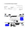
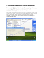
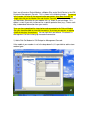
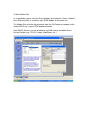
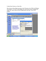
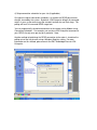
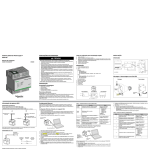
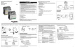
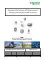
“Getting Started With ION Enterprise GPRS Modem Connections”
Connecting to a monitoring device installed at a remote site
PMC
Power Monitoring and Control
Global PMC Application Expertise Team
Release date:
Version:
8 May 2009
V1
Schneider Electric Industries SAS
Written by:
J.SU
Business Unit Power
Application note
Checked by :
Approved by:
PMC
UPDATES
Version /date
Written by
J.SU
V1/ 8 Apr. 2009
Modified pages
Origin and description of the modification
Initial version. Connection to retrieve data
from an ION 7650 meter that is equipped with
a Wireless Modem and installed in a remote
location.
1. Objectives
In cases where devices such as power meters must be installed in a remote location
(e.g., in a mountainous region), a fixed PSTN or Ethernet network connection may
not be available. In order to retrieve real-time and historical data from devices that
are installed in remote locations, it is usually possible to install a wireless modem at
the remote site. This document gives a basic example of how to set up an ION
Enterprise power monitoring system to communicate with a remote device that is
connected using a wireless (GPRS) modem.
The setup is almost identical to the situation where a traditional analog modem is
used to connect to the meter. The main purpose of this document is to highlight the
additional settings needed when using wireless (GPRS) modems. Those people who
have experience in connecting to a meter using analog modems (or embedded
modems in the meter communication card) may ignore all sections other than the
section describing wireless modem setup.
Background Information
1. What is GPRS, and how is it different from GSM?
GSM and GPRS refer to connection methods used by cellular (mobile) phone
networks. The devices used to communicate (i.e., mobile phones or wireless
modems) are the same, as is the physical communication medium (air), but the
underlying mechanisms for data transfer are different.
Source: http://www.mobile-phones-uk.org.uk/gprs.htm
Whilst GSM (2G) networks are excellent for voice calls, they are limited when it
comes to sending and receiving data. GSM phones use a technology called CSD
(Circuit Switched Data) to transfer data. CSD requires the phone to make a special
connection to the network before it can transfer data (like making a voice call) which
can take up to 30 seconds. Once connected, the data is sent or received and the
user is billed for the time spent online. Data transfer is relatively slow: 14.4 kbps
(kilobits per second) for GSM 1800 networks (Orange and T-Mobile) and 9.6 kbps for
GSM 900 networks (Vodafone and O2).
GPRS (General Packet Radio Service) is a method of enhancing 2G phones to
enable them to send and receive data more rapidly. With a GPRS connection, the
phone is "always on" and can transfer data immediately, and at higher speeds:
typically 32 - 48 kbps. An additional benefit is that data can be transferred at the
same time as making a voice call. GPRS is now available on most new phones.
Because GPRS transmits data in packets, the timeslots are not in use all the time,
but are shared amongst all users of the network. That increases the overall data
capacity of the network, and it also means that you are billed for the quantity of data
transmitted, not the time that you are online. It may mean that during busy times,
data transfer rates slow down, because the network will give priority to voice calls.
For the application example discussed in this document, the data transmission
method between the Power Montoring Server and the Remote Station (e.g., Power
Meter or Protection Relay) will be GPRS over a wireless network. Most wireless
modems have both GSM and GPRS transmission functions.
2. Basic terminology of telephone and modem systems.
For the explanation of terms such as PSTN and PABX, please consult the following
internet link:
http://www.bestdatasource.com/Glossary/networking_P.htm
2. Pre-requisites and Required Equipment
It is assumed that the reader has a working knowledge of the ION Enterprise
software and ION meters in general. The reader should be familiar with the content
of the ION Startup and ION Advanced Training Courses which are offered by the
Power Business Unit Training Organization.
a)
b)
c)
d)
e)
Computer with ION Enterprise installed (referred to as the Server)
External modem (can also be PCI or integrated) connected to Server.
Analog telephone line connection (e.g., PABX server)
Wireless GSM/GPRS Modem (e.g., MultiTech GPRS MultiModem)
ION 7650 meter (or other remote monitoring / protection device)
3. Functional Block Diagram of System
4. Wireless Modem Setup
Cautionary Note:
In some cases the signal strength of the wireless network (e.g., GSM cellular
network) will not be very strong at the physical location where the Power Monitoring
Device (RTU) must be installed. Examples of such locations would be a remote area
outside the city where network coverage is poor, or an industrial building where thick
concrete walls or other factors have degraded the signal.
Please ensure that wireless network reception is available at the installation location
of your RTU during the design and proposal phase of your project. You can test this
by trying to use your own personal mobile phone near the location of the RTU. Also,
if you place your GPRS modem at the intended installation location and power it on,
there are diagnostic commands available through Windows Terminal programs (e.g.,
Hyperterminal) that will report the actual signal strength. Please consult the
documentation of your GPRS modem for more information.
In some cases, additional work will be required to allow the GPRS modem to access
the wireless network. For example, in the case where reception inside an industrial
building is poor, you may consider mounting an antenna on the roof of the building
and routing a cable from the antenna to the modem.
The modem used in this example is the MultiTech MultiModem GPRS modem
(Model: MTCBA-G-F4).
http://www.multitech.com/PRODUCTS/Families/MultiModemGPRS/
The following settings should be considered:
a) SIM card and mobile service provider: your wireless modem uses a SIM card
to connect to the cellular phone network. This card will be issued by the
mobile service provider. Please ensure that you have GPRS (Data Services)
enabled for your SIM card. Also, your mobile service provider should give you
a list of the Access Numbers (phone numbers) for your SIM card. In some
cases, different numbers are used for voice calls and data calls. For reading
meter data, the data access number is used.
b) Basic modem setup: generally speaking, most wireless modems can be
configured via the Serial Port (RS-232). Using a terminal program such as
TeraTerm or HyperTerminal, you can make a serial connection from your PC
to the modem. Please consult the manual for your modem for detailed
information on AT commands. In this example, we configure the Baud Rate of
communication (which affects the link between the modem and the ION
meter), the number of rings before the modem will answer, and other
parameters. The following text shows the required settings for the MultiTech
modem – these should be entered after powering up the modem:
AT&F&D0
ATS0=1
OK
at+CICB=0
OK
at+FCLASS=0
OK
at+ifc=0,0
OK
at+ipr=9600
OK
at+CRC=1
OK
Command summary:
&D0 : ignore DTR (hang-up must be initiated by the user).
S0=1 : set to automatic answer (number of rings = 1)
+CICB=0 : set Incoming call mode to Data (not Voice)
+FCLASS=0 : set default mode of operation to Data (not Voice)
+IFC=0,0 : setting Flow Control parameters for local serial port (Mode = NONE)
+IPR=9600 : set fixed DTE rate of serial port (between meter + GPRS modem)
+CRC=1 : request debugging messages at serial port (for troubleshooting)
5. ION Meter Communications Setup
By establishing a Modem connection to the ION meter, we are making a serial
connection between the ION-E Server and the remote station. The physical layer of
the communication is similar to having an RS-232 serial cable linking the Server and
the ION meter. For this reason, minimal configuration is required for the ION 7650
with regards to the wireless modem connection.
1) Ensure that the Serial Port connected to the wireless modem is configured for the
same Baud Rate that you set for the modem (e.g., 9600bps).
2) Ensure that the Protocol on the 7650 meter COM port is set to “ION.” For
PowerLogic PM meters, it should be set to Modbus RTU.
If you are connecting the ION 7650 to the modem using an RS-232 cable, ensure
that the Comm Port of the 7650 (e.g., COM1) is correctly set for RS-232 mode.
7650 Serial Port Rx Timeout Setting
If you are using Acknowledgement (AckNaks) to detect errors in the communication
link between the ION7650 meter and the ION-E server, you may need to adjust the
Receive Timeout on the COM port of the ION7650 meter. This makes the link more
tolerant of long delays (e.g., ION-E is slow in responding to the meter).
We received reports that values such as 15 seconds were used in Hong Kong and
Australia for ION7650 meters.
6. ION Enterprise Management Console Configuration
The external (or PCI / integrated) modem of your Server computer should be
connected to the PSTN telephone network in the office building or Server room. This
could be a PABX router, or a telephone jack provided by your local
telecommunications company.
Please make a note of the Comm Port that has been assigned to your modem on the
Server computer. If you are connecting an external modem to your PC via the Serial
Port, this port may be COM1. Otherwise, for integrated modems on laptop
computers, or for PCI devices, you may need to check the Device Manager in
Windows as shown below.
Next, we will create a Dialout Modem, a Modem Site, and a Serial Device in the ION
Enterprise Management Console. This is shown in the following images. To connect
to the remote site after all the communication parameters have been entered, we
simply right-click on the Modem Site and choose “Connect.” It is also possible to set
up Connection Schedules for your modem site, as shown in the last image. This
option is useful if you wish to connect for a specific period of time (e.g., 2 hours each
day) to download information from your meters.
Once you have completed the steps below and connected to the Dial-out Modem
Site, you should be able to view real-time data in Vista from your device, or upload
historical data logs & waveforms. You can right-click and choose “Disconnect” in
Management Console to hang up the modem connection.
1) Add a Dial-Out Modem in ION Enterprise Management Console.
If the model of your modem is not in the drop-down list, it is possible to add custom
modem types.
2) Add a Modem Site
As shown below, please enter the Phone Number (also called the “Access Number”)
of the SIM card which is installed in your GPRS Modem at the remote site.
This Modem Site will make the connection from the ION Enterprise computer to the
remote GPRS site, using a PSTN telephone network.
Data (GPRS) Services must be enabled for your SIM card by the Mobile Phone
Service Provider (e.g., TELUS, Orange, VodaPhone, etc...).
3) Add a Serial Device on a Direct Site
We will make a Direct Serial connection to the ION meter on the COM1 or COM2 port
(for example). The Unit ID shown below is the value from the meter installed at the
remote site. Please make sure the ION7650 meter serial Port is set for “ION”
protocol.
4) Setup connection schedules for your site (if applicable)
One typical usage of connection schedules is to reduce the GPRS data transfer
charges incurred by the system. By default, ION Enterprise will poll all connected
meters in your system once every few seconds to check for new Data Logs. This
polling will result in increased GPRS usage fees.
You can automatically schedule connections to the remote site by Modem using
Connection Schedules. For example, you can force ION Enterprise to connect to
your GPRS site only once per day for a period of 1 hour.
Another method of optimizing the GPRS connection to the meter is to reduce the
polling rate of the Log Inserter using a Windows Registry setting. For more
information on this method, please consult the PMC Knowledge Base for ION
Enterprise.
7. Troubleshooting
Problem
Communication does
not work. Cannot see
data in Vista.
Communication does
not work. Carrier
Detect LED is not lit on
the remote GPRS
modem.
Suggestion
If the connection from the ION-E server to the remote
GPRS modem has been made successfully, the
Carrier Detect (CD) LED on the GPRS modem should
be lit, to show that a phone connection is active.
Check that the “CD” LED is on, and also that the
Receive and Transmit LED’s for data on the modem
are flashing when ION-E tries to communicate.
The modem connection has failed. Please check the
destination Telephone Number for the Modem Site in
ION Enterprise. Test the modem connection without
ION Enterprise using a terminal program such as
HyperTerminal in Windows. If you can connect
successfully using HyperTerminal, the problem may be
with the ION Enterprise setup.
8. Other information
If you have a network of several (e.g., two or more) meters installed in a remote
location, it is also possible to connect an RS-232 to RS-485 converter to the Serial
Port of the remote wireless modem. This would enable you to access data from
multiple devices using a single modem. Some wireless modems can be purchased
with an integrated RS-485 serial port. This saves you the cost of purchasing one
wireless modem for each remote monitoring device.
You can also choose Ethernet-enabled options for the MultiTech MultiModem. Using
an Ethernet-enabled modem at the remote metering site allows you to connect the
modem to an Ethernet-to-Serial gateway such as the PowerLogic EGX100, enabling
you to connect to a daisy chain of meters on an RS-485 loop.