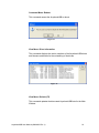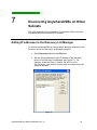
1
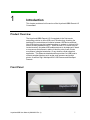
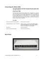
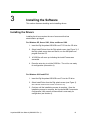
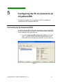
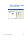
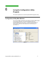
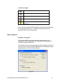
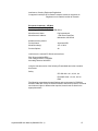
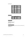
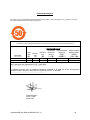
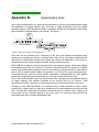
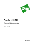
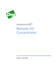
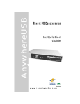
AnywhereUSB®
Remote I/O Concentrator
User Manual
www.digi.com
© 2009 Digi, Digi International, the Digi logo, RealPort USB, USB Over IP, AnywhereUSB, Watchport,
Edgeport, and Hubport are either trademarks or registered trademarks of Digi International, Inc. in the
United States and/or other countries. Microsoft, Windows, Windows NT, Windows Server, Windows Vista
are trademarks of Microsoft Corporation. All other trademarks are the property of their respective holders.
Information in this documentation is subject to change without notice and does not represent a
commitment on the part of Digi International.
Digi International provides this document ―as is,‖ without warranty of any kind, either expressed or
implied, including, but not limited to, the particular purpose. Digi International may make improvements
and/or changes to this documentation or to the product(s) and/or program(s) described in this
documentation at any time.
Digi International assumes no responsibility of any errors, technical inaccuracies, or typographical errors
that may appear in this documentation, nor liability for any damages arising out of its use. Changes are
made periodically to the information herein; these changes may be incorporated in new editions of the
publication.
For U.S. Government use:
Any provision of this document and associated computer programs to the U.S. Government is with
―Restricted Rights.‖ Use, duplication, or disclosure by the government is subject to the restrictions set
forth in, subparagraph (c) (1) (ii) of the Rights in Technical Data and Computer Software clause of DFARS
52.277- 7013.
For non-U.S. Government use:
These programs are supplied under a license. They may be used, disclosed, and/or copied only as
supplied under such license agreement. Any copy must contain the above copyright notice and restricted
rights notice. Use, copying, and/or disclosure of the programs is strictly prohibited unless otherwise
provided for in the license agreement.
AnywhereUSB User Manual (90000405 Rev. J)
3
Digi Contact Information
Product information is available on the Digi website, www.digi.com, including:
Support Forums
Knowledge Base
Data sheets/product briefs
Application/solution guides
For more information about Digi products, or for customer service and technical support, contact Digi
International.
To Contact Digi International by:
Use:
Mail
Digi International
11001 Bren Road East
Minnetonka, MN 55343
U.S.A.
World Wide Web:
http://www.digi.com/support/
Email
http://www.digi.com/support/
Telephone (U.S.)
(952) 912-3444 or (877) 912-3444
Telephone (other locations)
+1 (952) 912-3444 or (877) 912-3444
AnywhereUSB User Manual (90000405 Rev. J)
3
This Page is Left Intentionally Blank
AnywhereUSB User Manual (90000405 Rev. J)
4
Contents
1
2
3
4
5
6
7
8
9
Introduction
7
Product overview
Front Panel
Interpreting Status LEDs
Back Panel
7
7
8
8
Getting Started
9
In the Box
Cabling
9
9
Installing the Software
10
Installing the Drivers
Uninstalling the Drivers
10
11
Initial AnywhereUSB Configuration
12
Initial Configuration
12
Configuring the PC to Connect to an
AnywhereUSB
15
Connecting to the AnywhereUSB
15
Using the Configuration Utility Program
17
Configuration Unitlity Main Window
Menu Options
17
18
Discovering AnywhereUSBs on Other
Subnets
24
Adding IP addresses to the Discovery
List Manager
24
Hardware Specifications
25
Dimensions
Environmental
Power Requirements
25
25
25
Regulatory and Safety Information
26
AnywhereUSB User Manual (90000405 Rev. J)
5
Appendix A
29
AnywhereUSB Permitted Device List
Appendix B
31
Understanding Hubs
Appendix C
32
Configuring for Firewall Support
AnywhereUSB User Manual (90000405 Rev. J)
6
1
Introduction
This chapter provides a brief overview of the AnywhereUSB® Remote I/O
Concentrator.
Product Overview
The AnywhereUSB® Remote I/O Concentrator is the first remote
networking solution to utilize USB over IP® technology, breaking the
traditional five meter distance limitation between USB device and host.
Now USB devices may be located anywhere on a wired or wireless LAN –
without a locally attached host PC. Since the host PC or server may be
located remotely, AnywhereUSB enables devices to be deployed in harsh
or non-secure environments, making it ideal for point-of-sale, kiosks,
surveillance, industrial automation, or any mission-critical enterprise
application. This Ethernet-attached solution provides five USB ports to
connect peripheral devices such as bar-code scanners and receipt
printer, as well as Digi’s Watchport®/V2 USB Camera and Watchport
Sensors.
Front Panel
Figure 1
AnywhereUSB User Manual (90000405 Rev. J)
7
Interpreting the Status LEDs
The AnywhereUSB has six LEDs on the front panel: one System Status
LED and five hub LEDs. Each LED is capable of displaying three colors:
red, green, or orange.
System Status LEDs
On initial power up the System Status LED is orange for two seconds
while the system initializes and then blinks green. If DHCP is enabled and
the unit is booting up, the System Status LED will be orange while the
AnywhereUSB searches for a DHCP server. If it cannot find a DHCP
server, it will return to the default configuration to allow the Configuration
Utility to assign a static IP address.
Hub LEDs
Green hunting pattern across all LEDs
Not connected to a host PC.
Orange alternating on ports 1-3-5 and 2-4
Updating image in Flash. Do not remove power
from AnywhereUSB while flash is being updated.
Doing so will damage your AnywhereUSB.
Solid Green
Hub port is powered.
Green over Red hunting pattern
Please call customer service.
Back Panel
Figure 2
AnywhereUSB User Manual (90000405 Rev. J)
8
2
Getting Started
This section explains what comes with the AnywhereUSB and how to
connect it to a Network.
In the Box
AnywhereUSB/5
Digi AnywhereUSB USB over IP Installation CD v2.60
Power Supply
Ethernet Cable
Ethernet Crossover Cable
Cabling
To connect your AnywhereUSB to a Network:
1. Connect a standard Ethernet Network to your AnywhereUSB.
2. Connect the other end of the Ethernet cable to a 10/100/1000
BaseT switch or hub.
3. Connect one end of the power supply into the back of the
AnywhereUSB and the other end into an AC outlet.
AnywhereUSB User Manual (90000405 Rev. J)
9
3
Installing the Software
This section discusses installing and uninstalling drivers.
Installing the Drivers
Installing the drivers requires the use of an account that has
administrative privileges.
For Windows XP, Server 2003, Vista, and Server 2008
1. Insert the Digi AnywhereUSB USB over IP CD into the CD drive.
2. Select Install Drivers from the Digi splash screen (see Figure 3). If
the Digi splash screen does not launch, run the AWSplash.exe
program from the CD.
3.
A DOS Box will come up indicating the Install Process was
successful.
4. Press the enter key to exit the DOS Box. The unit is now ready
for configuration (see section 4).
For Windows 2000 and NT4.0
1. Insert the Digi AnywhereUSB USB over IP into the CD drive.
2. Select Install Driver from the Digi splash screen (see Figure 3).
Note: Windows 2000 and NT4.0 install v2.40 drivers only.
3. Continue until the installation process is complete. Once the
installation process is complete, the AnywhereUSB Concentrator
Configuration Utility screen will launch and is now ready for
configuration (see section 4).
AnywhereUSB User Manual (90000405 Rev. J)
10
Figure 3
Uninstalling the Drivers
To uninstall the AnywhereUSB drivers:
1. Launch the AnywhereUSB Configuration Utility from the Start
menu.
2. Select Preferences from the File menu and then click the Uninstall
button.
3. Reboot the PC to complete the driver removal.
AnywhereUSB User Manual (90000405 Rev. J)
11
4
Initial AnywhereUSB Configuration
This section explains how to configure the IP address in a new
AnywhereUSB unit.
Initial Configuration
To begin the initial configuration:
1. Launch the AnywhereUSB Configuration Utility from the Start
menu. A new AnywhereUSB will have a default IP address of
0.0.0.0 (see Figure 4) and must be configured before it can be
used by the host PC. Each AnywhereUSB is identified by its IP
address. If the AnywhereUSB is unconfigured, then the serial
number can be used for identification. Unconfigured
AnywhereUSBs are listed separately. For example, the
AnywhereUSB with serial number SW901F7005 below has not
been configured.
Figure 4
AnywhereUSB User Manual (90000405 Rev. J)
12
2. Double click on the Unconfigured AnywhereUSB entry, or select the
Unconfigured AnywhereUSB entry and click the Configure button.
3. Enter a Device Name that easily identifies the AnywhereUSB.
Figure 5-DHCP Enabled Configuration Figure 6-Static IP Address Configuration
To Configure DHCP:
1. Select the Enable button
2. When DHCP is enabled, the AnywhereUSB will wait for up to four
DHCP requests. If a DHCP response is not received, they
AnywhereUSB will default to its initial unconfigured state. Also,
AnywhereUSB will look for option 26 in order to determine the MTU
size (with 1500 being the default).
AnywhereUSB User Manual (90000405 Rev. J)
13
To Configure a static IP address:
1. Select the Disable button.
2. Enter and IP address manually.
3. The MTU size is configureable between 576 and 1500 bytes, with 1500
being the default. For the changes to take effect you must click the
Update button, which resets the AnywhereUSB.
AnywhereUSB User Manual (90000405 Rev. J)
14
5
Configuring the PC to Connect to an
AnywhereUSB
This section explains how to configure the PC to establish a
connection to the AnywhereUSB unit.
Connecting to the AnywhereUSB
In order to use the USB devices that are attached to the AnywhereUSB,
the PC must establish a connection to the AnywhereUSB by adding the
units IP address to the Connection List.
1. Launch the AnywhereUSB Configuration Utility from the start
menu. The utility displays a list of all AnywhereUSBs on your
local subnet and on any subnet configured in the Discovery List.
Figure 7
AnywhereUSB User Manual (90000405 Rev. J)
15
2. Select an AnywhereUSB from the AnywhereUSB Configuration
Utility Main Window and then either click the Connect button or
right click on the selected AnywhereUSB and click Connect from
the drop down box (see Figure 8). The host computer then
attempts to connect to the AnywhereUSB.
Figure 8
AnywhereUSB User Manual (90000405 Rev. J)
16
6
Using the Configuration Utility
Program
This section explains how to use the AnywhereUSB Configuration utility.
Configuration Utility Main Window
The AnywhereUSB Configuration Utility displays AnywhereUSBs grouped
by their subnet addresses. The Utility automatically discovers
AnywhereUSBs on the local subnet. To discover AnywhereUSBs on
other subnets, add those subnet addresses to the Discovery List
(see Section 7).
Figure 9
AnywhereUSB User Manual (90000405 Rev. J)
17
Icon Color Legend:
Green—Available For Connection
Gray, Bold Text—Connected to this computer.
Gray—In use by other host PC.
Red—Firmware is being updated.
AnywhereUSB IP Address has not yet been
configured
Note: After the AnywhereUSB Configuration Utility has been launched it
will reside in the system tray. To open the utility, double click the
AnywhereUSB icon in the system tray.
Menu Options
File Menu: Preferences
The AnywhereUSB Concentrator Detection option allows for the
configuration of how often and if the Configuration Utility queries the
network for AnywhereUSB units.
The Detection Timeout configures how long the Configuration Utility will
wait to hear from all the AnywhereUSBs before the Configuration Utility
updates the list of units in the Main Window.
Figure 10
AnywhereUSB User Manual (90000405 Rev. J)
18
Edit Menu: Connection List
Displays the IP addresses of the AnywhereUSB to which the PC will try to
connect. When an IP Address is added to this list, the Host PC
immediately tries to connect to the AnywhereUSB. If an IP Address is
deleted from the Connection List, the AnywhereUSB unit will disconnect
from the host PC and return to a ―Available for Host Connection‖ state.
Figure 11
AnywhereUSB User Manual (90000405 Rev. J)
19
Edit Menu: Discovery List
This command displays a list of subnet addresses of remote networks or
IP Addresses of individual units where the configuration utility will search
for AnywhereUSB units.
Figure 12
AnywhereUSB User Manual (90000405 Rev. J)
20
Command Menu: Configure
This command allows configuration of the TCP/IP parameters in the
AnywhereUSB. In a static IP address configuration the MTU size is
configurable between 576 and 1500 bytes, with 1500 being the default.
Note that when DHCP is enabled the AnywhereUSB looks for DHCP
option 26 in order to determine the MTU size (with 1500 being the
default).
Checking the Add to connection list box adds the IP address to the
connection list.
The Device Name field allows for a unique name to be given to the
AnywhereUSB.
Figure 13
AnywhereUSB User Manual (90000405 Rev. J)
21
Command Menu: Connect
This command allows the IP Address of the AnywhereUSB to be added to
the connection list once the AnywhereUSB is selected in the Main
Window.
Command Menu: Event Log
This command retrieves even information from AnywhereUSB. Use this
to gather information for Technical Support. This dialog is used to save
and clear the event log.
Figure 14
AnywhereUSB User Manual (90000405 Rev. J)
22
Command Menu: Reboot
This command causes the AnywhereUSB to reboot.
Figure 15
View Menu: Driver Information
This command displays the version numbers of the AnywhereUSB drivers
and firmware and allows for the uninstalling of the drivers.
Figure 16
View Menu: Refresh (F5)
This command updates the discovered AnywhereUSB listed in the Main
Window.
AnywhereUSB User Manual (90000405 Rev. J)
23
7
Discovering AnywhereUSBs on Other
Subnets
This section explains how to enable the Configuration Utility to discover
AnywhereUSB units on additional IP subnets.
Adding IP addresses to the Discovery List Manager
To discover AnywhereUSBs on other subnets, add their addresses to the
Discovery List in the Discovery List Manager dialog box.
1. Select Discovery List from the Edit menu.
2. Add the Subnet addresses or the IP Address of the individual
device to the Discovery List Manager (see Figure 17). For
example, to add the Class C network 192.168.2.x, enter
192.168.2.255. Note that the routers must be configured to pass
subnet broadcasts.
Figure 17
AnywhereUSB User Manual (90000405 Rev. J)
24
8
Hardware Specifications
This section proved the physical dimensions, environmental, and power
requirements of the AnywhereUSB.
Dimensions
Length: 4.35 in (11.05 cm)
Width: 7.20 in (18.29 cm)
Height: 1.03 in (2.61 cm)
Weight: 10.00 oz. (283.49g)
Environmental
Operating temperature: 32o F to 140o F (0o C to 60o C)
Relative humidity: 0% to 95% (non-condensing)
Power Requirements
Power to this product many be supplied by a UL Listed Direct Plug-In
Power Unit marked ―Class 2‖ or a UL listed power supply rated with a
minimum rating of 5 V dc 2.5 A if used in the U.S. and Canada or a power
supply with similar rating and approved by you local safety code if it is
used elsewhere. For polarity, see the following:
AnywhereUSB User Manual (90000405 Rev. J)
25
9
Regulatory and Safety Information
Federal Communications Commission (FCC) Regulatory Information (USA
only)
This equipment has been tested and found to comply with the limits for a Class B
digital device, pursuant to Part 15 of the FCC Rules. These limits are designed
to provide reasonable protection against harmful interference in a residential
installation. This equipment generates, uses, and can radiate radio frequency
energy and, if not installed and used in accordance with the instructions, may
cause harmful interference to radio communications. However, there is no
guarantee that interference will not occur in a particular installation. If this
equipment does cause harmful interference to radio or television reception, which
can be determined by turning the equipment off and on, the user is encouraged
to correct the interference by one or more of the following measures:
Reorient or relocate the receiving antenna.
Increase the separation between the equipment
and the receiver.
Connect the equipment into an outlet that is on a
circuit different from the receiver.
Consult the dealer or an experienced radio/TV
technician for help.
Warning: The connection of a non-shielded interface cable to this
equipment will invalidate the FCC Certification for this device.
FCC Regulation - Part 15
Declaration of Conformity (DoC)
This device complies with the requirements of the Code of Federal Regulations
listed below:
FCC Title 47 CFR, Part 15 Class B for a digital device.
Operation is subject to the following two conditions:
This device may not cause harmful interference, and
This device must accept any interference received, including interference that
may cause undesired operation.
Department of Communication (DOC) Notice (Canada only)
This Class B digital apparatus meets the requirements of the Canadian
AnywhereUSB User Manual (90000405 Rev. J)
26
Interference- Causing Equipment Regulations.
Cet appareil numérique de la Classe B respecte toutes les exigences du
Règlement sur le matériel brouiller du Canada.
European Community - CE Mark
Declaration of Conformity (DOC)
According to ISO/IEC Guide 22 and EN 45014
Manufacturer’s Name:
Digi International
Manufacturer’s Address:
11001 Bren Road East
Minnetonka, MN 55343
declares that the product
Product Name:
AnywhereUSB
Model Number(s):
301-1130-01
Product Options:
All
conforms to the relevant EU Directives listed here:
EMC Directive 89/336/EEC |
Low Voltage Directive 73/23/EEC
Amending Directive 93/68 EEC
using the relevant section of the following EU standards and other normative
documents:
Safety:
IEC 950:1991 +A1, A2, A3, A4
EN 60950:1992: +A1, A2, A3, A4
EMC
The following summarizes the specifications and requirements for EN55024,
EN55022 Class B & CISPR 22 Class B emission and immunity tests. If the actual
test levels are higher or different than required, these levels are listed in the
appropriate tables.
AnywhereUSB User Manual (90000405 Rev. J)
27
EN 55022 Class B
(1994 w/A1 1995)
Test
Specification
EN55024
Requirement
Electrostatic
Discharge
EN61000-4-2
+4 kV contact
+8kV air
Radiated Immunity EN61000-4-3
3 V/m
Electrical Fast
Transient Burst
EN61000-4-4
1kV (A/C), .5kV (I/O)
Surge
EN61000-4-5
2kV common mode
1kV differential mode
Conducted
Immunity
EN61000-4-6
3V rms
Magnetic
Immunity
EN61000-4-8
1 A/m Not Applicable
Voltage Dips &
Interrupts
EN61000-4-11
>95%, 30% & >95%
Test
Specification
EN55022
Requirement
Radiated
Emissions
—
Class B
Conducted
Emissions
CISPR 22
Class B
EN55024 (1998)
European Contact
Digi International
Joseph-von-Fraunhofer Str. 23
44227 Dortmund, GERMANY
49-231-9747-0
UL/CSA Safety Information
This device complies with the requirements of following safety standards below:
UL 1950, 3rd edition
CSA No. 950
AnywhereUSB User Manual (90000405 Rev. J)
28
China RoHS statement:
The Table of Toxic and Hazardous Substances/Elements and their Content shall apply to any product covered by
this manual and labeled with the following symbol:
The Table of Toxic and Hazardous Substances/Elements and their Content
as required by China’s Management Methods for the Control of Pollution from Electronic Information Products
Part Name
(部件名称)
301-1002-08
Lead
(Pb)
(铅)
X
Toxic and Hazardous Substances or Elements
(有毒有害物质或元素)
Hexavalent Polybrominated Polybrominated
Cadmium
Chromium
biphenyls
diphenyl ethers
Mercury
(Cd)
(Cr
(VI))
(PBB)
(PBDE)
(Hg)
(镉)
(六价铬)
(多溴联苯)
(多溴二苯醚)
(汞)
O
O
O
O
O
O: Indicates that this toxic or hazardous substance contained in all of the homogeneous materials for this
part is below the limit requirement in SJ/T 11363-2006.
表示该有毒有害物质在该部件所有均质材料中的含量均在SJ/T11363-2006 标准规定的限量要求以下.
X: Indicates that this toxic or hazardous substance contained in at least one of the homogeneous
materials used for this part is above the limit requirement in SJ/T 11363-2006.
示该有毒有害物质至少在该部件的某一均质材料中的含量超出SJ/T11363-2006 标准规定的限量要求.
Quality Manager
Austin, Texas
March 2007
AnywhereUSB User Manual (90000405 Rev. J)
29
Appendix A:
AnywhereUSB Permitted Device List
An option has been added to the AnywhereUSB product that will limit access to a set of select devices.
This option allows an administrator to build a list of supported devices by adding specific Vendor
ID/Product ID or Class values into the registry.
The AnywhereUSB will compare the IDs of each USB device (when the USB device is connected), with
the value(s) in the registry and if there is a match, the device will enumerate otherwise an ―unknown
device‖ message will appear in the Notification Area.
The key is located in the following location in the registry:
HKEY_LOCAL_MACHINE\SYSTEM\CurrentControlSet\Services\ionhub
The new key value is ―PermittedDevices.‖ This Multi String value contains a list of devices that the
AnywhereUSB will enumerate all other devices will show as ―unknown device.‖
The following are some examples of values in the permitted device list
For a hub use the value ―GENERICHUB‖ (Class_09 is not supported)
For a composite device use the value ―COMPOSITE‖
For specific device use Vid_xxxx&Pid_yyyy where xxxx and yyyy are the vendor id and product id
of the device
For a device class such as mass storage use Class_xx where xx is the class of device
COMMUNICATIONS
HUMAN INTERFACE
PRINTER
STORAGE
VENDOR SPECIFIC
02
03
07
08
FF
Examples:
To allow a specific USB device with an embedded hub (like an Edgeport/8):
PermittedDevices
REG_MULTI_SZ
Vid_1608&Pid_0215 GENERICHUB
To allow all Human interface devices such as mouse or keyboard:
PermittedDevices
REG_MULTI_SZ
Class_03
REG_MULTI_SZ
Class_03 Class_07
To allow all mice and all printers
PermittedDevices
AnywhereUSB User Manual (90000405 Rev. J)
30
The USB Device’s Vid/Pid values can be found using the provided AnywhereUSB View utility. The
fields are called idVendor and idProduct. In the following example, the highlighted USB Flash Drive
has the following properties:
idVendor:
0x13FE
idProduct:
0x1D00
AnywhereUSB User Manual (90000405 Rev. J)
31
Appendix B:
Understanding Hubs
Hubs, critical components in the plug-and-play architecture, are wiring concentrators that enable
the attachment of multiple devices, thus converting a single attachment point into multiple
attachment points. USB architecture allows a cascaded multiple hub configuration with certain
power limitations (explained later in this section). See figure 1.
PC
Host
Hubport
Edgeport
Edgeport
Hubport
Edgeport
bu s-powered hub
joystick
scanner
mouse
Figure 1: Example of a Typical Hub Configuration
Each hub has an upstream port, connecting to the host, and multiple downstream ports,
connecting to downstream devices, including other hubs. A hub can detect attachment and
detachment of downstream devices and enable and monitor the distribution of the power to
downstream devices via their integral hardware and the operating system.
Each USB device reports its power requirements to the operating system, which then enables
and disables the device as a function of its power requirements and the amount of available
power. High-speed devices typically need to be connected to a self-powered hub, which obtains
power from its external power supply and provides up to 500 mA for each downstream port.
Only simple devices, such as a mouse, can be connected to a bus-powered hub, which obtains
power from its upstream host and provides up to 100 mA for each downstream port.
Due to the limited available power for bus-powered hubs, cascading two bus-powered hubs is
an illegal topology, and devices connected to the second hub will not function. (USB
specifications limit the connection of a bus-powered hub to a self-powered hub or host only.)
According to the USB Specification, the maximum limit of hubs cascaded in series cannot
exceed five. In other words, you may have a maximum of five hubs between any device and the
host. This does NOT mean that the maximum number of hubs in a system is five. Indeed, up to
seven hubs can be connected parallel at any given level. You must tally both external and
embedded hubs when counting downstream hubs.
AnywhereUSB User Manual (90000405 Rev. J)
32
Appendix C:
Configuring for Firewall Support
To access an AnywhereUSB that is behind a firewall:
Your firewall must have a well known static IP address (for example 10.52.48.37).
The AnywhereUSB must have an IP address on the private subnet (for example
192.168.1.10).
Your firewall must be configured to allow TCP/IP and UDP/IP packets to pass
through port 3422.
The firewall must be configured to send these TCP/IP and UDP/IP packets directed
to the IP Address of the AnywhereUSB (in this example: 192.168.1.10).
You must manually add the address of the firewall to the Connection List.
Note that you can access only one AnywhereUSB through each firewall. For more information
on how to configure your firewall, refer to your firewall manual.
At this point the PC will attempt to connect to the AnywhereUSB.
If you would like AnywhereUSB Information to be displayed in the discovery window of the
configuration utility, you may add the address of the firewall into the Discovery List. Note that
AnywhereUSBs behind firewalls, as displayed in the discovery window, show the IP address of
their private network.
AnywhereUSB User Manual (90000405 Rev. J)
33