1
DISTRIBUTED CONTROL OF A SEGMENTED AND SHAPE MEMORY ALLOY
ACTUATED BIOLOGICALLY INSPIRED ROBOT
by
Oliver John Schubert
A thesis submitted in partial fulfillment
of the requirements for the degree
of
Master’s of Science
in
Electrical Engineering
MONTANA STATE UNIVERSITY
Bozeman, Montana
July 2005
©COPYRIGHT
by
Oliver John Schubert
2005
All Rights Reserved
ii
APPROVAL
of a thesis submitted by
Oliver John Schubert
This thesis has been read by each member of the thesis committee and has been
found to be satisfactory regarding content, English usage, format, citation, bibliographic
style, and consistency. It is ready for the submission to the College of Graduate Studies.
Dr. Hongwei Gao
Chair of Committee
Approved for the Department of Electrical and Computer Engineering
Dr. James N. Peterson
Department Head
Approved for the College of Graduate Studies
Dr. Bruce R. McLeod
Graduate Dean
iii
STATEMENT OF PERMISSION OF USE
I am presenting this paper in partial fulfillment of the requirements for a master’s
degree from Montana State University, I agree that the library may make it available to
borrowers under the rules of the library.
If I have indicated my intention to copyright this thesis by including a copyright
notice page, copying is allowable only for scholarly purposes, consistent with “fair use”
as prescribed in the U.S. Copyright Law. Requests for permission for extended quotation
from or reproduction of this thesis in whole or in parts may be granted only by the
copyright holder.
Oliver John Schubert
June 2005
iv
ACKNOWLDGEMENTS
I would like to thank the Idaho National Laboratories (INL) for the opportunity to
work on this project and both INL and Montana State University for financially
supporting my Master’s education. Thank you to the funding organization, the U.S.
Department of Energy, Office of Science, Office of Basic Energy Sciences, Under DOE
Idaho Operations Office Contract DE-AC07-99ID13727. I would also like to thank Dr.
Herschel B. Smartt, Timothy R. McJunkin, Karen S. Miller, and Richard Anderson for
their efforts in mentoring this project.
Thank you to my committee members Dr. Hongwei Gao, Dr. Robert Gunderson,
and Dr. Charles Tolle; your influence will guide me far beyond this work.
I could not have accomplished this work without the help of several individuals.
Thank you to Todd Trotter and Dr. Bruce Madigan for their support with the embedded
systems, Timothy Barnes for his AutoCAD and machining, and Shawna Lockhart and
Marty Peterson for their help producing the Pro/E models. I appreciate it all.
I would also like to thank my family for their love and encouragement through my
entire education. And to Ang, I could not have done it without you.
v
TABLE OF CONTENTS
1. INTRODUCTION ...................................................................................................... 1
VIPER Project ............................................................................................................. 2
VIPER Project Goals ............................................................................................. 3
2. PROJECT OVERVIEW.............................................................................................. 4
Problem Statement ....................................................................................................... 4
Project Objectives ........................................................................................................ 5
3. LITERATURE REVIEW............................................................................................ 6
Shape Memory Alloy ................................................................................................... 6
Heating Methods .................................................................................................... 7
Modeling.............................................................................................................. 10
Previous Work ..................................................................................................... 11
Snake Motion............................................................................................................. 15
Snake Robots ....................................................................................................... 17
Snake Motion Control .......................................................................................... 19
Embedded Systems .................................................................................................... 22
Toolchain ............................................................................................................. 24
4. APPROACH ............................................................................................................. 25
Mechanical Design..................................................................................................... 25
Segmented Structure ............................................................................................ 25
Actuation ............................................................................................................. 26
Construction......................................................................................................... 27
SMA Heating ............................................................................................................. 30
Position Control ................................................................................................... 32
Embedded System Development ................................................................................ 33
Network Topology ............................................................................................... 35
Toolchain Build.................................................................................................... 35
Root Filesystem.................................................................................................... 35
Busybox ............................................................................................................... 37
Application Transfer ............................................................................................ 38
Motion control ........................................................................................................... 38
Overview ............................................................................................................. 39
Detailed Operation ............................................................................................... 39
Transmission Control Protocol ............................................................................. 41
Example Operation............................................................................................... 42
vi
TABLE OF CONTENTS – CONTINUED
Important Issues ................................................................................................... 44
Flexibility............................................................................................................. 44
5. RESULTS................................................................................................................. 46
Manual Control.......................................................................................................... 46
Single Segment .................................................................................................... 46
Three-Segment ..................................................................................................... 48
Autonomous Control.................................................................................................. 50
Single Segment .................................................................................................... 50
Two-Segment ....................................................................................................... 51
Three-Segment ..................................................................................................... 53
Four-Segment....................................................................................................... 55
Summary of Results ................................................................................................... 58
6. CONCLUSIONS....................................................................................................... 60
Suggestion for Future Work ....................................................................................... 61
BIBLIOGRAPHY......................................................................................................... 63
APPENDICIES............................................................................................................. 67
APPENDIX A:
APPENDIX B:
APPENDIX C:
APPENDIX D:
APPENDIX E:
APPENDIX F:
APPENDIX G:
APPENDIX H:
APPENDIX I:
APPENDIX J:
Spider Toolchain Build..................................................................... 68
Using the Toolchain ......................................................................... 71
P501 Spider Development Environment Setup.................................. 74
Loading Spider Images..................................................................... 77
Busybox Configuration..................................................................... 79
Main C-program Flowchart............................................................... 81
Main C-program............................................................................... 83
Spider Scripts ................................................................................... 95
Current Controller Circuit ................................................................. 98
Inchworm Velocity Calculation ...................................................... 101
vii
LIST OF TABLES
Table
Page
3-1 Characteristics of SMA Wires................................................................................... 9
viii
LIST OF FIGURES
Figure
Page
3-1 Shape Memory Alloy Phase Transition ..................................................................... 7
3-2 Actuation Comparison .............................................................................................. 8
3-3 SMA Force and Diameter Relationship ..................................................................... 9
3-4 Hysteresis Property of Shape Memory Alloy........................................................... 10
3-5 Variable Area Fan Nozzle ....................................................................................... 11
3-6 Position of VAN ..................................................................................................... 13
3-7 SMA Actuated Biomimetic Hydrofoil..................................................................... 13
3-8 Snake Motion.......................................................................................................... 15
3-9 Concertina .............................................................................................................. 17
3-10 Choset’s Robot ..................................................................................................... 18
3-11 The OmniTread Robot .......................................................................................... 19
3-12 Hirose’s Hybris Robot .......................................................................................... 19
3-13 Yim’s Polybot....................................................................................................... 20
3-14 CONRO................................................................................................................ 21
3-15 Bentley’s Robot .................................................................................................... 22
3-16 Hirose’s ACM-R3................................................................................................. 22
4-1 Shape Memory Alloy Actuator ............................................................................... 26
4-2 CAD Drawing of Segment ...................................................................................... 28
4-3 Multi-Segment CAD Drawing ................................................................................ 28
4-4 Pro-E Drawing of Segment ..................................................................................... 29
ix
LIST OF FIGURES – CONTINUED
Figure
Page
4-5 Multi-Segment Pro-E Drawing................................................................................ 29
4-6 Machined Aluminum Segments .............................................................................. 30
4-7 Cross-Country Ski Skins ......................................................................................... 30
4-8 PWM Signal ........................................................................................................... 31
4-9 PWM Circuit Board ................................................................................................ 32
4-10 SMA Controller Block Diagram............................................................................ 33
4-11 System Block Diagram ......................................................................................... 33
4-12 P501 Spider Single Board Computer..................................................................... 34
4-13 Daisy-Chain Network ........................................................................................... 34
4-14 Daisy-Chained Computers .................................................................................... 35
4-15 P501 Development Setup ...................................................................................... 37
4-16 Positions of Inchworm Motion .............................................................................. 39
4-17 Single-Segment Positions for Inchworm Motion ................................................... 40
4-18 State Diagram of Inchworm Motion Control ......................................................... 41
4-19 Example Global Document ................................................................................... 43
4-20 Example Global Document ................................................................................... 43
4-21 Example Global Document ................................................................................... 43
5-1 Single-Segment Inching Cycle ................................................................................ 47
5-2 Three-Segment Inchworm Motion Cycle................................................................. 48
5-3 Three Segment Manual Control Setup..................................................................... 48
5-4 Single-Segment Autonomous Setup ........................................................................ 51
x
LIST OF FIGURES – CONTINUED
Figure
Page
5-5 Two-Segment Inchworm Motion ............................................................................ 52
5-6 Two-Segment Autonomous Setup........................................................................... 52
5-7 Three-Segment Inchworm Motion .......................................................................... 54
5-8 Position of Each Segment ....................................................................................... 56
5-9 Two-position Controller.......................................................................................... 57
5-10 Inchworm Results ................................................................................................. 59
xi
ABSTRACT
Today's robots are limited in mobility, flexibility, and scalability. Their rigid
bodies prevent operation in many environments and often restrict movement to a twodimensional space. Most robotic vehicles cannot operate in a confined space or
unstructured terrain and are incapable of climbing surfaces a fraction of their size. Their
stiff bodies significantly reduce their performance and present a major weakness. The
next-generation robot must be highly adaptable, flexible and capable of operating in
many environments. A possible solution is to create a flexible and scalable segmented
snake robot incorporating smart material for actuation. This project, in partnership with
The Idaho National Laboratories (INL), plans to implement a snake-eel-worm (SEW)
design to meet the needs of the next-generation robot as a part the Visual Inspection
Platform for Exploration and Research (VIPER) project. Snake-eel-worm platforms have
the dexterity to traverse highly unstructured amphibious and land-based terrain. To create
this flexible and scalable structure this work proposes the implementation of Shape
Memory Alloy (SMA) as the actuation device under distributed control of several
embedded computer modules. This project found that a mechanical prototype can
achieve snake-like locomotion while using SMAs under distributed control. A threesegment SMA-actuated structure moves in an inchworm motion under a distributed
control network consisting of several PowerPC single board computers (SBC).
1
CHAPTER 1
INTRODUCTION
Imagine for a moment a wheeled-robot with state-of-the-art sensors and high-tech
equipment patrolling the perimeter of a military base. The robot autonomously combs
the fence line to detect threats and alert human operators. This scenario runs smoothly
under ideal circumstances. However, consider if the robot’s path is obstructed with a
fallen tree, a flooded road, or another obstacle. It is possible the wheeled robot becomes
useless and cannot accomplish its goal.
While wheeled and tracked robot platforms are very common, they often become
useless in a dynamic environment. If the environment is unfamiliar, these robots struggle
to adapt. An effective robot must have precise knowledge of its environment. It is often
physically built with a particular environment in mind. Therefore, it always functions
properly when interacting with the “expected” surroundings whereas actual field
environments are not predictable; countless obstacles and changing terrain create a
treacherous atmosphere rendering many robotic devices useless.
Wheeled and tracked robots lack mechanical flexibility since the rigid structures
are incapable of adapting to unexpected terrain. The overall dimensions of typical robots
dictate the surface on which they can travel. For instance, it is difficult for any wheeled
robot to travel across a surface that is a fraction of its own size; the body simply does not
have the ability to grip and provide the necessary traction for movement. A reduction in
size could permit the robot to perform a specific task or navigate a particular environment
2
but the functionality, capabilities, and the payload of the device also decrease, limiting its
usefulness.
This brings about the second major weakness of rigid wheeled robots: scalability.
In many cases, it is not feasible to change the size of these robots. The locomotion and
other technologies may not function on different scales. Such is the problem with many
electromechanical and mechanical devices. The miniaturization of these parts becomes
prohibitively complex and expensive.
In essence, a flexible and scalable structure is required to navigate an unstructured
environment. What structure allows for this diverse adaptive operation? The SEW.
Advantages of a SEW robot include both the flexibility to accommodate difficult terrain
and the scalability of size. Biological snakes prove scalable by ranging from a small
garter to a large python; all move with similar methods. Perhaps the greatest advantage
of SEW-like design is the ability to move with several different forms of locomotion,
such as lateral undulation, concertina, side-winding, and caterpillar which are easily
identified in biological snakes.
The VIPER Project
The Idaho National Laboratory (INL) is actively constructing a biologically
inspired snake-eel-worm (SEW) robot within its Visualization Integration Platform for
Exploration and Research (VIPER) project. The VIPER project focuses on developing
serpentine robots for diverse tasks such as search and rescue as well as exploration and
reconnaissance. Snake-like robots would have several advantages in the areas of
3
reconnaissance and exploration. Typically, wheeled robots are restricted to relatively
smooth terrains lacking confined spaces. On the contrary, a SEW design can free robots
from these restrictions and conform to a dynamic contour, including significantly small
spaces, all while allowing continual maneuverability.
VIPER Project Goals
The goal of the VIPER project is to develop a SEW robot that is light enough for
a single individual to deploy, guide, and easily reconfigure.
These requirements stem
directly from the project's primary goal of reconnaissance missions in highly unstructured
environments, such as collapsed structures within earthquake zones. The design will
ultimately permit the replacement of modules or segments for added functionality such as
sensor packages and computing power. Future project goals will include remote
operations within hazardous environments and cooperative observation and manipulation
tasks. Much of the advanced visualization requirements for complete implementation of
the VIPER program reconnaissance missions are under parallel development [1-7]
4
CHAPTER 2
PROJECT OVERVIEW
The mobility and flexibility of a SEW structure requires a multi-segments design
under a distributed control architecture. The control architectural goal is to manipulate
the mechanical body into forms of SEW locomotion. By basing the initial SEW design
on smart material actuators it will achieve a high degree of miniaturization possibilities,
perhaps to the nanoscale size. Further, with the consideration of future technology, a
solar-fuel cell system can replace the batteries which will vastly increase the operation
lifetime with sunning cycles. To achieve these ends, the SEW robot requires several
special design considerations covered in the remaining sections of this paper.
Problem Statement
This thesis addresses the problem of incorporating a mechanical structure and
control methods into a modular autonomous platform capable of SEW locomotion. The
intent of this thesis work is to construct and control a biologically-inspired SEW-like
robot utilizing shape memory alloy (SMA) actuators. A segmented SEW design provides
the desired mobility and flexibility while SMA actuators provide a method of scaling
without major redesigns. The objective is to effectively coordinate the actions of each
segment into a "global" locomotion or gait. This requires control strategies for both the
individual actuators and multiple segments to obtain inchworm motion under a
distributed control system consisting on PowerPC single board computers.
5
Project Objectives
The aim of this research is to build an autonomous robot capable of SEW
locomotion that meets the VIPER project requirements: modular, and scalable. We intend
to make a SEW structure that is both flexible, to conform to any terrain, and scalable, so
that the control and actuation techniques function at any size without major redesigns.
For instance, the diameter of the SEW design could increase or decrease to accommodate
a particular task. A segmented structure will allow the SEW to change in length. This
can also help accommodate certain tasks while increasing functionality through added
processing power, the sensor package, or more physical power.
Specifically, the objectives are as follows: 1) Build a segmented structure capable
of autonomous SEW locomotion, 2) Incorporate smart material actuation through the use
of SMA pistons 3) Configure an embedded network of single board computers to control
individual segments and 4) Create a distributed control algorithm to synchronize a foursegment structure into SEW locomotion, which allows the SEW to move without any
commands from a “head” segment.
6
CHAPTER 3
LITERATURE REVIEW
Shape Memory Alloy
Future SEW robots will likely incorporate some type of artificial muscle, instead
of hydraulics, pneumatics or motors. The VIPER project incorporates the “smart
material” shape memory alloy as an actuation solution. The material is gaining use in
engineering designs and applications as the demand for sophisticated actuation
techniques continues to motivate SMA research [8].
Shape memory alloy metals belong to the class of “smart” materials since they
respond to a stimulus; heat [9]. Discovered in 1932, SMA exhibits a large physical
deformation when exposed to varying temperatures. Nickel-Titanium (Nitinol),
developed in 1965 by the Naval Ordnance Laboratory, is the most common composition
of SMAs. In this thesis the terms “shape memory alloy” and “Nitinol” are
interchangeable.
The material can return to a specific geometry when exposed to heat. This
“memorization” is known as the Shape Memory Effect (SME) [9] and creates a
noticeable size change. The shape memory effect is the primary mechanism for the shape
change which transforms the material’s microscopic structure. A phase change causes
the crystalline structure to align, decreasing the size of the material. Martensite is the low
temperature phase in which the unit cell of the material is a distorted cube. The austenite
is the high temperature phase where the unit cell is almost a perfect cube. As the
7
temperature of the material increases, the unit cell structure changes from a Martensite to
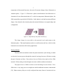
Austenite phase. Figure 3-1 illustrates a phase transformation from Martensite to
Austenite of a two-dimensional unit cell. At the low temperature Martensite phase, the
SMA material has a great deal of flexibility. In this phase it can bend into many different
shapes. Once heated to the Austenite phase the material deforms to its original shape and
configuration.
Figure 3-1: Shape Memory Alloy Phase Transition [9]
The shape change is recoverable as the material cools and returns to the
Martinsite phase. This transformation results in a useful motion and force, which is often
harnessed as an actuator useful to many applications.
Heating Methods
The most efficient method to induce the phase transition is joule heating, in which
an electrical current passes through the material causing electrons collisions creating
thermal vibration and heat. Researchers also use fluids to heat and cool the SMA
material. Often cooling is done through convection with the ambient environment.
The physical size of SMA wire has several advantages as an actuator. First,
SMAs have a very large power-to-weight ratio which traditional actuators cannot match
[10]. Shape memory alloys are easily configured into many forms of actuation devices
8
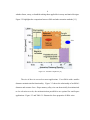
whether linear, rotary, or bundled making them applicable in many mechanical designs.
Figure 3-2 highlights the comparison between SMA and other actuation methods [11].
Figure 3-2: Actuator Comparison [11]
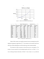
The size of the wire can scale to meet applications. Even SMAs with a smaller
diameter maintain similar functionality. Figure 3-3 shows the relationship of an SMA’s
diameter and actuator force. Shape memory alloy wire can theoretically be miniaturized
to the sub-micron scale; the miniaturization possibilities are optimal for small-space
applications. Figure 3-3 and Table 3-1 illustrate the force properties of SMA wires.
9
Figure 3-3: SMA Force and Diameter Relationship [12]
Table 3-1: Characteristics of SMA Wires [12]
Further, SMA actuators can simplify mechanical structures reducing the need for
additional components in applications [13]. Wire actuators are also noiseless and do not
suffer from vibration disturbances associated with many motor actuation methods.
The drawback of SMA actuation is the inefficient power consumption. The
amount of current required for joule heading depends on the size, see Table 3-1. For
wires with larger diameter than those of Table 3-1 the resistance is very small and
10
requires an impractical amount of current to create the necessary heat. The larger
diameter creates less resistance in the wire while adding more material heat.
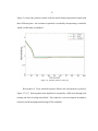
Shape memory alloy material suffers from hysteresis. Hysteresis occurs when a
system does not react to applied forces or inputs. Instead the performance depends
heavily on the heat transfer with the ambient environment. When the actuation heat is
removed the wire does not immediately regain its shape. Figure 3-4 shows a typical
heating and cooling cycle of a SMA wire.
Table 3-4: Hysteresis Property of Shape Memory Alloy
Modeling
Development of a mathematical model which incorporates the nonlinear behavior
of SMA as it undergoes temperature, stress, strain, and phase changes is difficult task.
Researchers continue to study how to model and control these materials [14].
Ikuta developed a variable sub layer model in which the percentages of the SMA
phases are described mathematically with respect to time [14]. The strain is calculated
for a given load by weighting the strain from the different phases. This work is the basis
11
for many nonlinear models including Madill and Wang’s differential equation where the
temperature-current relationship is used to capture the dynamics of a SMA actuator [15].
This model is well-suited for position control systems since electric current is the input
and source of heat.
ρcV
dT
= Ri 2 (t ) − hA[T (t ) − T∞ ]
dt
(3.1)
Previous Work
Despite the difficulties to model and control SMAs are incorporated into many
applications with a variety of control methods. This literature review concentrates on
SMA wires as opposed to other shapes such as a tube or bar.
Barooah and Rey, of the United Technologies Center, investigate the use of SMA
wires for a variable area fan nozzle (VAN) which compares to the VIPER project’s
actuation techniques [16]. The size of SMA wire in the VAN is of comparable size so
control methods are also useful to study. They experiment with several different
controllers starting with a proportional (P). Figure 3-5 shows the nozzle flap controlled
with SMA actuators. The initial assumptions were that linear control strategies, such as
proportional, do not function well due to the strong nonlinearities of the SMA actuation
process.
12
Figure 3-5: Variable Area Fan Nozzle [16]
Their results indicate the proportional-integral-derivative (PID) controller has the best
performance. In the PID controller the supplied voltage, Vc(t) is a weighted sum of the
error (e), the integral of the error, and the derivative of the error. The weighting factors
or gains are represented by Kp and Kd in the following differential equation.
VC (t ) = K P e + ∫ edt + K d
de
dt
(3.2)
The derivative term reduces an overshoot of the position while the integral compensates
for the steady-state error. In the experiments the PID controller is suitable if the SMA
wires are small and have a low thermal inertia; the ability to store heat. Barooah and Rey
also state that an inverse hysteresis model can perform quite well but was too complex
for real-time control. The main actuation objective is to avoid an overshoot since it takes
more time for the wire to cool then it does to heat. A simple control algorithm in
implemented:
1. If the measured error is large, the best action is to supply the
maximum power possible. If the error is negative no power is
supplied.
2. When the position is close to the desired one, the current is
reduced intelligently, and cut off before the target is reached.
3. When (1) and (2) are not satisfied (the measured position is close
to the target) voltage is continuously controlled.
13
Figure 3-6 shows the position control of the fan nozzle under proportional control with
three different gains. An overshoot in position is avoided by incorporating a controller
which is sufficiently overdamped.
Figure 3-6: Position Control of VAN [16]
Researchers at Texas A&M incorporate SMAs into a biomimetic hydrofoil,
Figure 3-7 [17]. Each segment of the hydrofoil is actuated by a SMA wire through joule
heating and forced cooling using fluids. Their objective was to incorporate an adaptive
hysteresis model and proportional-integral (PI) controllers.
14
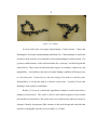
Figure 3-7: SMA Actuated Biomimetic Hydrofoil [17]
They conclude that the adaptive hysteresis model is too complex for a six-segment
hydrofoil, each segment with two SMA wires, and concentrate on the PI controller.
Results indicate good performance with a linear control strategy if the wires are small and
have a low thermal inertia. Ikuta’s literature also suggests similar results [8].
In other work Dickinson and Wen [18] do not directly compensate for hysteresis
with and inverse model but use proportional closed-loop feedback to control the position
of a flexible beam. Their work shows that SMA position stability is possible with a
linear control strategy. The controller is shown in the following equation. The input
current, u, is zero when the position, x, is greater then the desired position, x d. When the
position is below the set point the input current is proportion to the error by a gain factor
k.
u 2 = 0,
= k ( x d − x ),
x > xd
x < xd
(3.3)
Dickinson and Wen also use this controller with a fictitious desired position instead of a
15
fixed value. The fictitious set point is mapped from a table which is updated through an
adaptation law. The mapping of a different set point helps reduce the steady-state error.
The control strategy functions well with both fixed and mapped set points and results in
an actuation bandwidth of 1-2 Hz.
Still other research uses varying control schemes from P to adaptive variable sublayer models [19] [20]. Most control methods focus on either position feedback or
reverse models to control the position of an SMA actuator. It is often the case that openloop control is very difficult since the hysteresis model is usually changing depending on
stress and life cycle [9].
Snake Motion
A snake’s adaptability stems from its physical body type as well as its several
methods of locomotion. To move between land and marine environments a snake may
simply use a different gait. To realize the advantages of SEW locomotion; one must
study how these organisms accomplish biological movement.
A SEW organism moves by shifting its body in a cyclic pattern or gait and by
pressing on the surrounding environment. Several SEW gaits are discussed in Hirose’s
extensive study [21]. The most common modes of locomotion are undulation,
concertina, side-winding, and rectilinear or caterpillar. The most identifiable type of
locomotion is undulation or serpentine motion in which an S-shaped curve propagates
through the body of the SEW organism creating friction with the environment causing
forward motion.
16
Figure 3-8: Snake Motion [22]
Biological snakes move in a side-winding motion by lifting their body off the
ground and placing it in the direction of motion. When side-winding, the snake’s body
has only several points of contact with the ground. As a snake lifts one part of its body,
another part serves as a base. The snake then pushes off this base and moves latterly.
Caterpillar motion resembles a ripple traveling vertically through the snake. In
this case, the scales push on the ground as a curve is created vertically in the snake. This
motion is the same as undulation except restricted to the vertical plane of motion where
friction is created on the bottom of the SEW organism.
Concertina is another valuable form of locomotion which snakes use to navigate
difficult terrain. With concertina the snake uses half of its body as a base and extends the
other half. If a snake encounters a difficult obstacle it may bunch its back half and extend
its front half forward over or onto the obstacle. When the front half reaches a surface it
can then provide traction and bring the back half forward. This type of motion allows a
snake to adapt to an unstructured terrain and is often used inside holes as seen in Figure
3-9.
17
Figure 3-9: Concertina [23]
The few gaits discussed here show the adaptability of SEW organisms to move
through various environments. This trait of the SEW locomotion is ideal for many robot
platforms.
Snake Robots
Today’s mobile robots perform work too difficult or dangerous for humans.
However, their inability to adapt to different environments leaves a significant void
which the SEW robots will help fill.
Snake-Eel-Worm designs aim to capitalize on the robust and dynamic locomotion
of real SEW organisms. SEW locomotion is applicable to areas such as search and
rescue, military reconnaissance, pipe and bridge inspection, hazardous environment
operation, as well as the medical field for active endoscope and catheters [24].
In general, SEW robots can access environments and perform tasks wheeled
robots and humans cannot. A SEW robot, has the potential to traverse objects many
times its own size. To illustrate this, consider how a snake can climb a tree or swim
18
across a lake while the Mars rovers Freedom and Independence, two of the most
sophisticated robots to date, probably cannot climb a boulder a fraction of its own height.
The snake’s ability to traverse unstructured environments makes them ideal to
many industries, organizations, and professions. A primary goal in developing several
snake robot platforms is search and rescue. Erkmen, illustrates how many local
governments are not equipped and lack an appropriate immediate response to natural or
manmade disasters [25]. Current rescue efforts still need a sophisticated and highly
capable robotic search tool. This is the primary objective of Choset at Carnegie Mellon
University [26]. Choset is developing several robots for use in urban search and rescue
(USAR). One of Choset’s robots is seen in Figure 3-10.
Figure 3-10: Choset’s Robot
Choset’s earlier research included work for NASA’s JPL and focuses on a snake which
probed through rubble.
In addition to Choset, other researchers combine snake-like features with
traditional robots. An example of this hybrid approach is the OmniTread robot [27]
developed by engineers at the University of Michigan, Figure 3-11.
19
Figure 3-11: The OmniTread Robot
Figure 3-12: Hirose’s Hybris Robot
The OmniTread is controlled by a human operator through a tethered cable. It is able to
climb objects twice its size. The Hybris robot, seen in Figure 3-12, from the Hirose and
Yonedia Lab uses a similar design [21].
A good overview of actuation techniques is Downling’s doctoral thesis [38]. The
DC motor is the most common actuator in robotic applications, included in many SEW
platforms such as Hirose’s 20-segment active cord mechanism (ACM) [38]. SEW
designers often consider artificial muscles such as “smart materials” too experimental or
impractical and revert to the DC motor.
The newest actuator method involves Electroactive polymers (EAPs) [11]. EAP
actuators exhibit a fast response time and a large actuation force. However, the large
voltage required and the high temperature transition point often yields EAPs inadequate
for low temperature and robotic applications.
Snake Motion Control
The coordination of a highly articulated body in three dimensions is a difficult
motion control problem. Centralized control is the most common control scheme in
20
which each movement is the result of a command sent from some central processing unit.
Decentralized or distributed control is the result of decision making and control
commands from several processing units. Yim [29] uses a centralized control protocol to
control his Polypod robot.
Figure 3-13: Yim’s Polybot
In this application the locomotion gait is represented in a control table. Each column of
the table is a sequence of actions. A Polybot module will transition from one sequence to
the next coordinated by the central controller. Yim suggests the results of this method are
versatile, scalable, and that the complexity is manageable. Shen and Stoy [30] employ
what they call “hormonal” signaling in their CONRO robot. In this method a signal
propagates through the length of the snake causing different actions in segments. With
this method of control their snake achieves a motion of approximately 5 cm/s.
21
Figure 3-14: CONRO
Several studies also investigate path planning of snake motion. Choset and
Henning have developed a path planning simulation [26]. Choset attempts to exploit the
geometric snake structure to accomplish accurate path planning for snake motion. The
geometry and kinematics of the snake determine the “road map” and thus the path the
snake follows. Their work is divided into three aspects: accessibility, connectivity, and
deportability. Accessibility is the study of a snake finding a path that will bring it close
to a desired point. Connectivity is the traversing of the path to reach the point.
Deportability is leaving the path to reach the actual point. Currently Choset and
Henning’s work is purely in simulation.
Bentley [31] uses an evolutionally algorithm for adaptive control and creates a
damage-resistant snake. The snake is able to learn which sequences of movement
provide the best locomotion. His results show recoverable motion when an actuator is
damaged. Bentley incorporates SMA actuators in his snake design and concludes that
hysteresis in negligible when the wires are small (i.e. 0.15mm).
22
Figure 3-15: Bentley’s Robot.
Hirose [21] is a standard reference for the study of snake kinematics. Several
researchers go farther then just controlling the snake and also adaptively discover the
network topology. Researchers use a centralized controller for snake motion and also for
discovering the network topology [32]. Hirose also incorporates distributed control in his
ACM-RC, Figure 3-15, in which segments listen for their neighbor’s angular position.
Figure 3-16: Hirose’s ACM-R3 [23]
Embedded Systems
The platforms discussed in the Snake Robots background section are advancing
several SEW technologies such as locomotion, actuation, and mechanics. Most rely on
23
tethered cabling for power and control. Others still lack the on-board processing
necessary for autonomous operations such as image recognition. A truly useful SEW
platform must operate autonomously on some level, such as locomotion or navigation.
The autonomous platform must possess several capabilities such as motion control, image
recognition, path planning, and communication. These functions, among others, are
extremely difficult for a small microcontroller or embedded computer. It is likely a
cluster of computers will meet the needs of these autonomous functions. Eight and 16-bit
microcontrollers generally lack the processing power and network support for use in a
cluster. Therefore a cluster computer is usually a 32-bit processor or greater running an
operating system (OS). The VIPER project uses the Embedded Linux operating system
since it is well suited for embedded computing and contains many desired networking
features.
While there are several embedded operating systems such as VxWorks, NetBSD,
Windows XP, Linux has several advantages. Linux is freely distributed and free to
download which has created a large community of support. Linux allows an embedded
system to be highly configurable in both hardware and software. The ability to multitask
and enable multi users is also an advantage. Usually Linux is platform independent
enabling it to run on a number of processor architectures. Thus little or no software
changes are needed for new hardware.
Linux has vast networking capabilities which allows for easy exchange of
information with other embedded devices or systems. It also allows for many embedded
systems to be updated easily. This networking also permits distributed processing and
clustering. For this reason several of the world’s supercomputers are Linux or UNIX
24
based. The most common network interface for embedded systems is Ethernet since it is
well documented and inexpensive.
Linux further supports a variety of other bus and I/O interfaces allowing the
embedded systems to interact with the environment. There are numerous types of busses
and interfaces to choose from or develop into any embedded system. Linux has varying
levels of support for many of the most common busses and interfaces including ISA, PCI,
PCMCIA, PC/104, VME, CompactPCI, Parallel Port, SCSI, USB, GPIB, I2C, I/0, Serial
Port.
Toolchain
Embedded Linux and other embedded operating systems generally lack the
resources to create the programs and applications they will eventually run. Most
embedded applications are created on a larger more powerful computer known as the
“host” and then are transferred to the platform which runs the application, the “target.”
Often the computer building the application is not the same processor architecture as the
embedded system. Therefore the application must be built with the embedded system
architecture in mind with a toolchain. A typical toolchain consists of an editor for writing
code, a compiler and a linker to transform the code into an executable. More specifically
the toolchain consists of gcc, glibc, and binutils.
25
CHAPTER 4
APPROACH
This chapter discusses the methods to realize the research objectives of Chapter 2.
Ideally the overall device will help implement and test a variety of mechanical, electrical,
computer processing, and networking solutions. This chapter presents the mechanical,
electrical, and computer processing tactics for building a robot capable of SEW
locomotion.
Mechanical Design
The mechanical design maintains the VIPER project goals by providing a skeletal
structure which supports various types of SEW locomotion. It further enables the use of
SMA actuation techniques and the associated electronics and control hardware. The
mechanical framework must also accommodate the additional components required for
autonomous SEW locomotion.
Segmented Structure
A segmented SEW structure creates a flexible and scalable mechanical device. It
makes the body physically and functionally flexible. Adding segments could conceivably
add processing power and sensing capabilities or to scale the physical size to adapt to a
particular application. In all, the segmented structure allows the SEW to adapt to many
situations.
26
Actuation
Another objective of VIPER project, and this research, is to integrate smart
material actuation devices. Shape memory alloy is one of the most viable smart
materials. Several companies provide brand-name SMA wire such as Dyallonyol’s
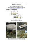
Flexinol which must be incorporated into an actuator. This project selects an SMA wire
already in actuator form. The Electric Piston from Raychem is an SMA wire enclosed in
a piston configuration [33].
Figure 4-1: Shape Memory Alloy Actuator
When heated, the SMA wire pulls the plunger inside the metal casing. This design has an
overextension spring which helps protect the wire from excess strain.
The actuator is not necessarily optimal in this application but the piston
configuration is easily integrated into the mechanical structure. These pistons require
four amperes of current supplied by Lithium Polymer batteries.
27
Construction
The SEW segment is sufficiently large to house a variety of electronic and
mechanical components. The diameter of the end plate is the primary dimension which
dictates the usable space inside the segment. Consequently, the endplates, which act as
the ribs of the SEW supporting the weight of the structure, have a diameter of 4.5 inches.
The endplates are in the shape of a hexagon to prevent a multi-segment structure from
rolling.
A center post connects the two endplates. A telescoping double-ended universal
joint originally connected each end plate to the center post but this configuration was
under-constrained causing a segment to collapse. The segment was then constrained to 3Degrees of freedom by removing one universal joint and fastening one end of the center
post directly to an endplate. This configuration allows one endplate to swivel and
providing rigidity in a segment.
Actuators attach in parallel to the end plates with swivel joints permitting a wide
range of motion. A mounting plate attaches to the center post and serves as an area for
electronic components.
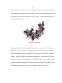
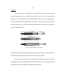
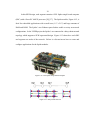
Below in Figures 4-2 and 4-3 are CAD drawings of a SEW segment [34]. Figures
4-4 and 4-5 show a Pro-E representation of the mechanical design [35].
28
Figure 4-2: CAD Drawing of Segment
Figure 4-3: Multi-Segment CAD Drawing
29
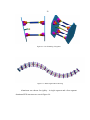
Figure 4-4: Pro-E Drawing of Segment
Figure 4-5: Multi-Segment Pro-E Drawing
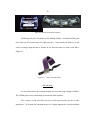
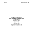
Aluminum was chosen for rigidity. A single-segment and a four-segment
aluminum SEW structures are seen in Figure 4-6.
30
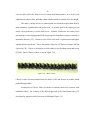
Figure 4-6: Machined Aluminum Segments
Machining took place on an Emco CNC milling machine. Eventually all the parts
were built out of Lexan because of weight concerns. Cross country ski skins act as the
scales creating a high amount of friction in one direction and very little in the other,
Figure 4-7.
Figure 4-7: Cross-Country Ski Skins
SMA Heating
As described earlier any heating method can cause the shape change in SMAs.
The VIPER project uses joule heating to actuate the SMA position.
The custom current controller meets several requirements specific to this
application. To fit inside the constrained space of a single segment the circuit board must
31
have a small area.
The weight of a typical controller is often negligible; however,
consideration is still given to it, since weight is critical to this project. The current
controller pulses the maximum current allowed by the battery, which is rated at 5 Amps.
To vary the SMA temperature, and thus the piston length, the current controller
provides a variable amount of current through the use of a pulse-width-modulation
(PWM) chip. A typical PWM signal is seen in below.
Volts
ON
OFF
Time
Figure 4-8: PWM Signal
When the PWM signal is high, the current is ON and flows through the SMA, otherwise
when the PWM signal is low the current is OFF. The high voltage level causes current
flow by activating a HEXFET transistor. These transistors turns ON (i.e. completes the
circuit) when a 5 V signal is placed on the input terminal. The percent of time the PWM
signal is high is known as the duty cycle. If the signal is high for 10 microseconds and
low for 90 microseconds the duty cycle is 10%. The duty cycle of the PWM is set by
control commands received on the I2C communication bus. Pulsing current at a high
frequency (kilohertz) creates slight temperature variations by changing the duty cycle
32
which allows for greater control. Additionally, a PWM current is one of the most
efficient heating methods.
The current controller board also incorporates additional components such as an
analog-to-digital (A/D) converter for the SMA position feedback and an input-output I/O
expander for future needs. The current controller board is seen below.
Figure 4-9: PWM Circuit Board
Position Control
The SMA actuation is currently under two-position or bang-bang control in which
the actuator has only two desired positions. The equations below describe the controller
output signal, m(t), and the error signal e(t). Typically in two-position control m(t)
remains at either a maximum or minimum value as described by to following equations.
m(t ) = M 1
= M2
e(t ) > 0
e(t ) < 0
(4.1)
The values of M1 and M2 relate to the electric current duty cycles of 15% and 0%
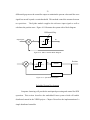
respectively. Figure 4-10 shows the block diagram for the two-position controller. A
33
differential gap causes the controller output to maintain the present value until the error
signal has moved beyond a certain threshold. This method control the actuator between
two positions.
The Spider module supplies the reference input signal as well as
calculates the position error. Figure 4-11 illustrates the system with a block diagram.
Differential Gap
M1
Input Signal
m
e
+
M2
-
Figure 4-10: SMA Controller Block Diagram
M1
m
e
+
-
Position
Actuator
M2
A/D Sensor
Figure 4-11: System Block Diagram
Embedded System Development
Computer clustering will provide the anticipated processing and control for SEW
operation. This section describes the embedded Linux system which will enable
distributed control in the VIPER project. Chapter 5 describes the implementation of a
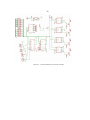
simple distributed controller.
34
In this SEW design, each segment contains a P501 Spider single board computer
(SBC) with a PowerPC 440GX processor [36] [37]. The Spider module, Figure 4-12, is
ideal for embedded applications with a small area (1.9” x 2.8”) and large amounts of
RAM and ROM. The Spider’s two Ethernet ports further enable a variety on network
configurations. In the VIPER project the Spider’s are connected in a daisy-chain network
topology which supports a SEW segmented design. Figure 4-13 shows how each SBC
and segment are nodes of the network. Below is a discussion on how to create and
configure applications for the Spider modules.
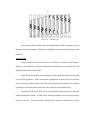
Figure 4-12: P501 Spider Single Board Computer
Figure 4-13: Daisy-Chain Network
35
Network Topology
The spider modules are physically connected in a daisy-chained network
configuration in which the computers are in series. In actuality each link functions as its
own network allowing a Spider module to only communicate with its immediate
neighbors. Both of a Spider’s Ethernet ports have identical internet protocol (IP) address.
A routing table on each spider contains the IP address of neighboring computers. Figure
4-14 is a diagram of the VIPER network topology with corresponding IP address for each
segment.
Crossover Ethernet Cables
153.90.197.251
153.90.197.252
153.90.197.253
153.90.197.XXX
Figure 4-14: Daisy-Chain Computers
Toolchain Build
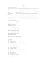
The toolchain creates the embedded application for the Spider. The SBC vendor,
General Microsystems (GMS), cannot legally supply the toolchain and its utilities under
the GNU Licensing Agreement but can provide directions of how to obtain the same
toolchain which they used for development. The toolchain is downloaded from the Denx
website [38]. See Appendix A for detailed steps to setting up the toolchain.
36
The toolchain image is configured for a specific host/target environment. In this
instance the toolchain is configured to produce applications for a PowerPC target from an
i686 host to create executable applications for the Spider.
Root Filesystem
The Embedded Linux command line interface is very similar to its desktop
counterpart. Both permit users to move through the filesystem folders (i.e. /usr /bin /proc
/mnt) which contain various documents and programs. The Spider’s root image; which is
a block of memory which the embedded system uses like a disk. GMS provides a RAM
disk image which is modified to meet the needs of the VIPER application. See Appendix
B for more details.
To modify the root filesystem, the RAM disk is first extracted, uncompressed and
mounted as a temporary device on the host system. Now anything can be added or
removed such as files, directories, Linux commands, device files, etc. Once properly
configured the image is unmounted and compressed. The toolchain command mkimage
creates the actual image used by the Spider. Appendix D describes to steps to load an
image to the Spider.
37
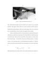
Figure 4-15: P501 Development Setup [38]
Busybox
Included in the root filesystem is the Busybox executable [40]. Often considered
a cornerstone of embedded Linux systems, Busybox is a single executable which contains
the functionality of most Linux commands such as cd, ls, ifconfig, etc. When a command
is typed at the command prompt of the embedded system it is linked to the Busybox
executable which runs as that command. Busybox is widely used in embedded
applications because of its small size (roughly 200 KB) and familiar functionality.
Developers can easily obtain the source code and build the Busybox executable with the
desired functionality. It is simply built like another Linux application but with the
toolchain for the desired platform. Using the make menuconfig command it is easy to
38
select the desired commands. This is useful in development as well as running
applications on the embedded system.
Application Transfer
Minicom is a common terminal emulator which allows developers to issue
commands and initiate file transfers to the target system. Minicom uses the RS-232 serial
link to communicate with the Spider module.
When the Spider is powered the bootloader prompt appears in the Minicom
terminal window. The bootloader is a target application which conducts low-level
hardware initialization and ultimately starts the operating system [39]. The VIPER
project uses the U-boot bootloader, provided by GMS, to load application images to the
Spider. See Appendix D for the steps to load the U-boot to the Spider. The U-boot
“Flash” command uses TFTP to retrieve RAM disk image from the development
workstation. It then places the RAM disk into the user-specified memory location on the
Spider. For details of this installation see Appendix D. The kernel and RAM disk images
contain the complete Spider application.
Motion Control
This section describes the distributed controller. The control scheme is important
to realizing the goals of the modular SEW design. The embedded system described
previously will apply distributive control to the SEW assembly to create an inchworm
motion. In this control system each segment contains a Spider computer module to
control the actuators as well as communicate with neighboring segments.
39
Overview
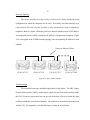
The inchworm type motion is accomplished by the SEW structure curving its
body into a C-shape and returning to a flat position, as in Figure 4-16. With the use of
the snake skins mentioned in section 3-1 this cyclical shape change will result in forward
motion.
(a)
(b)
Figure 4-16: Positions of Inchworm Motion
To keep the system modular, segments do not issue commands to other segments.
No “head” segment functions as a centralized controller. Segments base their movements
on the environment which indicates the overall shape of the SEW. As a result the control
protocol must allow all segments to assess environmental data and make an informed
decision based upon the information from neighboring segments. Segments will assess
the environment data and determine the action. Sharing this information through the high
speed communication network the segments can actuate concurrently creating the smooth
inchworm motion.
Detailed Operation
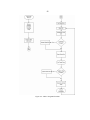
The system-level overview is best described with a state diagram and logic
equations. The objective is for the segments to collectively curve into the orientation
40
seen in Figure 4-16. If the segments move to these positions at the same time the
coordinated movement will move the structure forward.
L=0
L=1
(a)
(b)
Figure 4-17: Single-segment Positions for Inchworm Motion
Single segment position control is accomplished with the heating control
hardware discussed earlier. Actuating the segments at the same time is the crucial factor.
This coordination relies on the data exchanged over the Ethernet links. Segments must
exchange information describing the position of the end plate. Position feedback from
the sliding resistor is the source of all environmental information. For this study when
the plates of a segment are parallel as in Figure 4-17(a) it has a local state, L, of zero, (0).
Conversely when the bottom pistons are actuated, as in Figure 4-17 (b) it has a local state
of one, (1). Likewise when the entire structure is in the form of Figures 4-17 (a) and 4-17
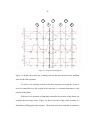
(b), the Global states, G, are A and B respectively. Figure 4-18 shows the state diagram
of the control protocol.
41
L1ŸL2ŸL3Ÿ…ŸLN
L1+L2+L3+…+LN
L1’+L2’+L3’+…+LN’
A
B
L1ŸL2ŸL3Ÿ…ŸLN
Figure 4-18: State Diagram of Inchworm Motion Control
Each segment will use the local information of other segments to determine the global
state and select the appropriate action. For instance, if the global state is A, segments
will wait for all local states to become zero and then transition to global state B. A
transition corresponds to a state of actuation whereas global states A and B corresponds
to states of rest. All segments then wait for the global state to become B before it
actuates towards a local state of 1.
To exchange information each segment first determines its own local state by
reading the A/D. If the reading is above or below certain threshold values the state is
determined to be either a 1 or 0. For this work a local state of 1 corresponds to an A/D
reading of 80 or higher and a local state of 0 corresponds to 20 or lower.
Transmission Control Protocol
Once known the local state is exchanged with its neighboring segments using the
Transmission Control Protocol (TCP). The segment will make its local state available by
functioning as a TCP server. To receive that information the neighboring segments must
request this document and read the data. Transmission Control Protocol is a connectionoriented communication service. It is also a byte-stream service; a sequence of bytes is
sent from the source to the destination [39]. The bytes are “buffered” since they are
42
placed into blocks which then go to the IP layer. The communications link is duplex
since it can send and receive data concurrently. Netcat is the specific TCP utility used to
transmit data across the Ethernet connections. Netcat is as a reliable backend tool which
can easily interact with programs and scripts and can handle both inbound and outbound
connection using either TCP or UDP [41]. This utility comes on most distributions of
Linux and UNIX operating systems. With these systems netcat is a feature-rich utility
which is highly configurable for almost any type of connection. The Busybox netcat can
function as a server or client. As a server it listens for inbound connections and provides
the requested file. When a client it can request data from a server or can pipe data to
another connection.
With each segment functioning as a server information propagates to all the
segments. Middle segments have the additional responsibility of passing multiple local
state values to other segments. All segments will operate under the same algorithm and
test the global data equally. As a result, they should all observe the completion of a
global state and independently decide to move toward the correct state.
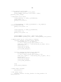
Example Operation
To further illustrate the control protocol a simple example is presented. To start
out the structure is lying flat on the ground. Segment #1 reads the A/D and determines
the local state is 0 and stores it in the global document which neighboring segments
request. The global document which Segment 1 requests from Segment 2 is seen in
Figure 4-19.
43
Seg1:
Seg2:
Seg3:
Seg4:
0
0
0
0
Figure 4-19: Example Global Document
By reading these values Segment #1 determines that the structure is lying flat on the
ground. Thus to create motion it must actuate towards a local of 1. The next time it
requests information it receives the following document:
Seg1:
Seg2:
Seg3:
Seg4:
0
1
0
0
Figure 4-20: Example Global Document
It decides that it needs to keep actuating its pistons. The next time it observes the
environment document it sees:
Seg1:
Seg2:
Seg3:
Seg4:
1
1
1
1
Figure 4-21: Example Global Document
It decides a global state has been reached and actuates its pistons towards a local state of
0. This process is a continuous loop. Ideally, the position of each segment will be
identical to all of its neighbors. The optimal positions, with respect to time, of the
individual segments in a three-segment structure could be represented graphically as a
sine wave. If data transmission was instantaneous all segments would observe the global
state at exactly the same time allowing them to all actuate between states in unison.
44
Important Issues
Communications delay is one concern to this network and the control scheme. It
will take longer for the outer segment to acquire the state of the entire system. If a
segment oscillates around a local state it will write corresponding values to the global
document. This may cause distance segments to see a false local state. This could result
in the observation of different global states. In this case a segment could actuate in
different directions making the system highly unstable. The combination of the high
speed Ethernet network and the low cycle-time of the actuators will help stabilize this
problem. It is conceivable that in a 4 or 8-segment structure, all environment data could
reach end to end within one second creating a communication rate of approximately 1
Hz. The cycle time for a piston is specified as once per minute or 1/60 Hz. For that
reason the order of magnitude difference in cycle times allows segments to make well
informed decisions.
Another main concern with distributed networks is synchronization. The
observation of the global state allows segments to observe the same data and make
informed decisions. As a result there is no need for a global clock to synchronize all
segments.
Flexibility
This control approach can be flexible in that it can be applied to structures with
varying number of segments and other gaits of locomotion. The challenge is properly
defining the required states needed for different types of locomotion. In more complex
schemes individual segments would need to achieve desired states of position, velocity,
45
and acceleration. For instance, a serpentine type motion may require the velocity of the
preceding segment as the environmental data. The segment would then try to move its
end plate with the same velocity but slightly out of phase.
This distributed control protocol addresses the issues of communication delay of
synchronization. Each segment will observe its current state as well as the state of the
entire system and make a decision based upon both.
In the future, segments will observe more environmental information through
sensors such as accelerometers, gimbals, and GPS. Additional capabilities of individual
segments will minimize inter-segment communication and reduce the communication
delay. With the current structure the described protocol is a way of allowing an
individual segment to control its own functionality based on environmental observations.
The segments will automatically operate in an inchworm type of motion. This type of
motion could also be accessed from another “main” program if inchworm motion was the
best solution.
46
CHAPTER 5
RESULTS
This chapter describes the integration of mechanical, electrical, and embedded
control subsystems for inchworm movement. Discussed are several trials ranging from
single-segment motion under manual control to three-segment motion under autonomous
control. Each trial includes a discussion of the physical setup, performance of the
structure, subsystems operation, and general notes and observations.
Manual Control
Single Segment
The first locomotion trial involves an aluminum single segment which includes
the current controller and battery housed inside. A human operator controls the piston
actuation by turning the current ON and OFF with a constant duty cycle of fifteen
percent. The top and bottom actuators are controlled as pairs to produce the inching
motion seen in Figure 5-1.
47
(a)
(b)
(c)
Figure 5-1: Single-segment Inching cycle.
For this motion trial the above figures are not associated with the local states described in
Chapter 5. Instead the segment is controlled to the positions shown to produce forward
motion.
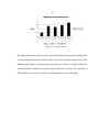
As documented in [42] the segment moves approximately 0.5 inches per minute.
Although slow, it demonstrates the mechanical design moving under its own power for a
sustainable period of time. As a result of this trial the current controller board was
redesigned with larger current traces and an A/D for position feedback. It was also
evident that a position control system would improve performance. Often the piston was
supplied with an incorrect amount of current. When too much current is supplied the
SMA wire overheats and requires a longer cooling period. If too little is supplied the
current must be turned ON again. Both situations reduce the cycle time and the overall
speed of a segment.
48
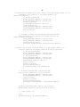
Three-Segment.
The manual control of a Lexan three-segment assembly allows a human operator
to control each segment with a desktop computer into the desired states. A simple circuit
allows the computer’s parallel port to function as an I2C bus which provides the actuation
into the motion in Figure 5-2 where the associated local and global states are listed to the
right.
The circuit schematic is seen in Appendix I. The setup is also seen in Figure 5-3.
L1 = 0
L2 = 0
L3 = 0
GS = A
GS = B
(b)
L1 = 1
L2 = 1
L3 = 1
GS = A
(c)
L1 = 0
L2 = 0
L3 = 0
(a)
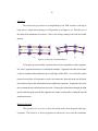
Figure 5-2: Three-Segment Inchworm Motion Cycle
Figure 5-3: Three-Segment Manual Control Setup
49
Under the PC control the structure moves approximately 1.375 inches per minute.
The 3-segment desktop control experiment reveals valuable insight to the mechanical
design. The structure cannot achieve a noticeable body curvature with the current piston
configuration. The telescoping universal joint provides no pivot point; actuation causes
the endplates to move closer together while still remaining nearly parallel. This causes a
decrease in the overall length of structure, with virtually no forward movement, instead
of the desired C-curvature. A slight difference in the telescoping range possibly
prohibits this motion in the Lexan segments. It is likely telescoping center post length is
different than the aluminum single-segment test. By temporarily removing the
telescoping aspect of the center post, a pivot point is created at the expense losing a
degree of freedom. This does not greatly affect any of the common SEW gaits discussed
in Chapter 3 but does eliminate the possibility of locomotion by the compression and
expansion of each segment also known as accordion locomotion. Also, this modification
most likely reduces the concertina motion slightly restricting the extension of the body.
In this test it was observed how the pistons are not optimal in this mechanical
structure. Being spaced equally from the center post the bottom pistons cannot overcome
the weight of the structure to create a C-curve. For this work the bottom pistons are
temporarily repositioned directly underneath the center post to provide an increased
moment around the pivot point. This configuration creates the necessary force to produce
the desired curvature. This change does decrease the lateral or azimuth mobility of the
structure since only the top pistons provide an actuation force in the horizontal directions.
However, SEW gaits such as lateral undulation are still possible with optimal SMA wires
50
[33]. The top pistons remain in the original configuration since the force they provide,
along with gravity, cause the structure to easily flatten against the surface. When an
optimal piston is found they can easily be placed in the original configuration.
Overheating and under heating the SMA wires were again common problems
resulting in reduced cycle times.
In this trial the 3-segment structure moves under its own power. Each segment
included the battery and the current controller. Not included on the structure is any sort
of processing device.
Autonomous Control
The SEW device must now intelligently control itself with the embedded system
and protocol discussed in Chapter 3.
Trials with one, two, and three segments are
conducted.
Single-Segment
The single-segment trial utilizes the feedback sensor and Spider control to obtain
inchworm locomotion as seen in Figure 5-1. The test setup is seen in Figure 5-4. The
application program running on the Spider is a modified version of the protocol discussed
in Chapter 3.
51
Spider Computer
Current Controller
Lexan Segment
Figure 5-4: Single-Segment Autonomous Setup
The single-segment inches forward at approximately 1 inch per minute. All
subsystems seem to operate properly. No modifications to the mechanical structure were
made as a result of the tests. Results indicate the Spider module is able to move the end
plate into the desired position and is ready to be synchronized with other segments.
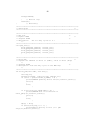
Two-Segment Motion
The two-segment setup incorporates communication to synchronize the plate
movement. The fixed plates of each segment are arbitrarily attached end-to-end.
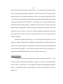
Actuating corresponding pistons on each segment will yield forward motion as in Figure
5-5. The Spider’s onboard LEDs show the global and local states for observation and
debug purposes. The physical setup is seen in Figure 5-6.
52
(a)
L1 = 0
L2 = 0
GS = A
(b)
L1 = 1
L2 = 1
GS = B
L1 = 0
L2 = 0
GS = A
(c)
Figure 5-5: Two-Segment Inchworm Motion.
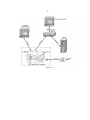
Figure 5-6: Two-Segment Autonomous Setup
Again, a slightly modified version of the protocol discussed in Chapter 3 controls
the two-segment assembly. The control program does use the same communication
techniques to determine the global state and control the pistons.
53
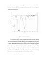
The two segment setup moves approximately 1.5 inches per minute. Although the
application program observes a global state change nearly instantaneously, as seen on the
LEDs, there is some lag in the mechanical response due to the SMAs pistons. A pair of
pistons actuates pulling on the end plate and continues until a global state is observed
causing the opposite pistons to actuate. However, the first pair has had little time to cool
and resists any extension. The opposite pair induces no movement on the end plate until
the pistons cool. This causes the segments to be temporally out of sync before reaching
the same state. It appears the cycle time is too fast and the segments cannot
instantaneously change between positions of Figures 5-5(b) and 5-5(c). When a state is
reached time is needed for the SMAs to cool.
Three-Segment Motion
The three-segment setup incorporates the distributed control protocol of section 33. The Spider modules communicate in order to achieve a synchronized motion. In this
test the segments are assembled in a homogenous fashion with each movable end plate
attached to the next segment’s fixed plate as seen in Figure 5-3.
The 3-segment structure achieves a speed of approximately 1.83 inches per
minute. The overheating and cooling problem was observed in this test as well, however
with a more debilitating effect. The sliding resistor does not take into account the length
of the overextension spring. A piston can fully actuate and still cause no movement on
the end plate but instead lengths the overextension spring. When this occurs the program
will see the reading of the A/D and interpret a false position and state. A segment may
54
then move towards the other state when it has not fully reached its original target reactuating the pistons which have not cooled.
a)
b)
c)
Figure 5-7: Three-Segment Inchworm Motion
L1 = 0
L2 = 0
L3 = 0
GS = A
L1 = 1
L2 = 1
L3 = 1
GS = B
L1 = 0
L2 = 0
L3 = 0
GS = A
55
The mechanical design of the segments has a noticeable affect on movement. The
segments appear to actuate one after another instead of concurrently even though all
corresponding piston are actuating. The leftmost segment of Figure 5-7 has less force
opposing the movement of its end plate and thus takes less current to change its position.
The left segment creates more weight for the middle end plate and requires the middle
segment’s pistons to actuate longer.
Figure 5-8 shows the segments actuating synchronously. The horizontal lines on
each plot represent the threshold values which determine the local state. When all the all
of the positions are above or below the horizontal lines a global state is reached and
actuation begins towards the opposite state. The transition to a global state is denoted as
a vertical dashed line in Figure 5-8. Segment 1 in these figures corresponds to the
rightmost segment in the figures above.
Segment 1 has the most overshoot of a target position when actuating toward a
local state of zero. The actuation process of Segment 1’s top piston is underdamped since
the weight of a single segment is the only load. The position of Segments 2 and 3 are
much more accurate with less overshoot and acceptable steady state error. The rise time
appears to be the result of their location in the structure. Both segments 2 and 3 reach the
target state with minimal overshoot or steady-state error.
56
A
B
A
B
A
B
B
Figure 5-8: Position of Each Segment
Figure 5-8 further shows how Seg 3 changes states in the least amount of time and then
waits for the other segments.
To achieve the inching motion in the three-segment test setup the piston is
actively controlled since the weight of the structure is a constant disturbance to the
position of the plates.
With just a two-position or Bang-Bang controller the position of the piston can
oscillate about its target value. Figure 5-9 shows how the weight of the structure is a
disturbance pulling against the actuator. The pistons must be re-actuated to maintain a
57
local state; this creates difficulty obtaining a global state especially if several segments
oscillate near the target value.
Figure 5-9: Two-position Controller
To avoid this oscillation, current is continually delivered to the SMA, although
only enough to maintain the temperature and keep it in an actuated state once a local state
is reached. In most three-segment trials no segments oscillated around the target value
before a global state was reached. The regular duty cycle of the actuation current is
roughly twelve percent and three percent when a state is reached. The two-position
controller works in the one and two-segment cases because of the minimal amount of
disturbance seen by the plate enabling them to easily hold their positions.
58
To avoid overheating a 15 second delay is added in every cycle. The pistons
appear to hold their target position while not overheating the SMA wire to the point
where the opposing force cannot overcome it. This allows the just-actuated pistons time
to cool. Then when the opposing piston actuate they will not oppose the force of those
pistons.
Four-Segment
The same distributed control scheme is used to control a four-segment SEW
structure. However, this attempt was unsuccessful due to insufficient force provided by
the SMA pistons. During actuation of the bottom pistons all force was absorbed by the
overextension of the springs causing no displacement in the end plates. Thus the SEW
structure did not exhibit any curvature nor forward motion.
Summary of Results
As mentioned earlier the snake structure obtains constant forward motion in an
inchworm-like fashion. The combined effect of the pistons further increases the
locomotion capabilities as seen in Figure 5-10.
59
Figure 5-10: Inchworm Result
The single-segment was slower because of the full actuation of the pistons requiring them
to reach a higher temperature and take longer to cool, decreasing the frequency of cycles.
With the multi-segment setup the pistons are required to actuate less while yielding the
same locomotion. And this in turn increased the maximum cycle time. The cycle time of
SMA improves as the strain is relatively small compared to the overall length.
60
CHAPTER 6
CONCLUSION AND SUGGESTIONS
This thesis work accomplished the objective of inchworm motion with a
segmented, SMA-actuated SEW structure under distributed control. The resulting
platform further supports the ideas and goals of the VIPER project. The segmented
structure enables the platform to be modular. Future segments will be added or removed
to customize a SEW device for specific applications. The SMA actuation is scalable,
furthering SEW technologies to many applications. Although not optimal for this SEW
structure the SMA piston proves a segmented structure can move under its own selfcontained power. The three-segment structure moves at 1.83 inches per minute compared
to the maximum speed of 2.095 inches per minute calculated in Appendix J. The
embedded network of Spider computers can be utilized as a cluster to provide processing
power, autonomous operations, and difficult tasks, such as image recognition and path
planning. The distributed control method further allows the systems to maintain the
segmented structure and enable modular capabilities. This protocol permits the segments
to collaborate and synchronize their movements into inchworm locomotion. Segments do
not receive commands instead they base their actions on environmental information
received from neighboring segments. Specifically the goals reached are as follows: 1) A
flexible, lightweight, mechanical SEW structure was built 2) Shape memory alloy piston,
are effectively incorporated as the actuation method, and 3) A distributed control system
was constructed to control and coordinate segment actuation.
61
The goal of SEW locomotion was accomplished in a three-segment structure but
not a four segment structure due to an ineffective actuation force. Had the pistons been
optimal for the weight of a four-segment structure it is probable the distributed control
system would have resulted in forward locomotion.
This mechanical assemble and future prototypes will help increase the capability
of mobile robots to navigate unstructured terrain. The SEW structure of this thesis work
is a precursor to a device capable of adapting to any land or sea environment.
Suggestions for Future Work
The next step of the VIPER project is to complete a dynamics study to design an
optimal SEW structure. Although this platform is capable of inchworm locomotion with
SMA pistons, the size and placement of each is not optimal. This is evident in the
structure’s speed and cycle time. Shape memory alloys and other smart material have
been proven to exhibit an actuation frequency of 1-2 Hz. An actuation frequency in the 1
Hz range would be a significant step forward in achieving SEW locomotion comparable
to that of real SEW organisms. This would create a structure optimized with the right
SMA wire size as well as piston placement and configuration. The proper actuation force
would dictate the proper piston configuration (i.e., straight wire, spring, bundled actuator,
etc) and placement.
Several improvements are also needed in the embedded systems. The current
control protocol uses a high-level form of message passing which creates extra
communication overhead. Rather than transmitting text documents, socket programming
62
could allow communication directly between the C-programs eliminating the need for
Linux shell utility commands. Along these lines a more efficient network is possible;
instead of communication among only direct neighbors, the segments could send and
receive information from all other segments. The optimal approach is to include routing
and bridge capabilities with each SBC allowing each segment to send IP packets to all
segments when new information becomes available. Information could be routed to
segments until it reaches the proper destination. Additionally, with segments functioning
as bridges and routers the network has the capability of automatically recognizing its
composition (i.e. number of segments and location of each segment). For instance a
network could involve segments which connect to the preceding segment on the first
Ethernet port and the following segment on the second. This could allow the segment
without a connection on the first Ethernet port to begin a message passing scheme to
determine the topology. For instance, it could recognize it is the first segment and
transmit a message to the second segment with a command to identify itself as the second
segment. This could continue down the length of the network structure with the last
segment identifying itself by no connection on its second Ethernet port.
Future objectives for the VIPER project include untethered operation as well as
locomotion of additional SEW gaits such as lateral undulation. Both possible with
optimal actuators and piston configuration.
63
BIBLIOGRAPHY
[1]
Tolle, C.R., McJunkin, T.R., Rohrbaugh, D.T. and LaViolette, R.A. “An
Optimal Cover Based Deffnition of Lacunarity for Ramiffed Data Sets",
Physical D, Vol. 179, pp.129-152, May 2003.
[2]
Tolle, C.R., McJunkin, T.R., and Gorsich, D.J. “Sub-Optimal MCV Cover
Based Method for Measuring Fractal Dimension", IEEE Transactions on Pattern
Analysis and Machine Intelligence, Vol. 25, No. 1, pp.32-41, Jan. 2003.
[3]
Gorsich, D. Tolle, C.R. and Gerhart, G. “Why Multiresolution?", 8th Annual
Ground Vehicle Survivability Symposium Proceedings, 1997.
[4]
Gorsich, D., Tolle C.R., and Gerhart G., “Wavelet and Fractal Analysis of
Ground Vehicle Images", 8th Annual Ground Vehicle Survivablitity Symposium
Proceedings, 1997.
[5]
Gorsich, D., Tolle, C.R., Karlsen, R. and Gerhart, G. “Wavelet and Fractal
Analysis of Ground Vehicle Images", 1996 SPIE Symposium Proceedings,
1996.
[6]
Tolle C.R., Gorsich D., “Sub-Optimal Covers for Measuring Fractal
Dimension", Proceedings of the 1996 Rocky Mountain NASA Space Grant
Consortium Conference, Utah State University, Logan, UT, 1996.
[7]
Gorsich D., Tolle C.R., Karlsen R., Gerhart G., “Wavelet and Fractal Analysis
of Ground Vehicle Signatures", 7th Annual Ground Vehicle Survivability
Symposium Proceedings, 1996.
[8]
Hunter, I.W., Lafontaine S., 1992. “A Comparison of Muscle with Artificial
Actuators,” Technical Digest of the IEEE Solid-State Sensor and Actuator
Workshop, pp. 178–185.
[9]
Mavroidis, C., Pfeiffer, C., Moslesy, M., Conventional Actuators, Shape
Memory Alloys, and Electrorheological Fluids, Automation, Miniature Robotics
and Sensors for Non-Destructive Testing and Evaluation, April, 1999.
[10]
Erkmen, I., Erkmen, A., Matsuno, F., Chatterjee, R., Kamegawa, T., Snake
Robots to the Rescue, Serpentine Search Robots in Rescue Operations, IEEE
Robotics & Automation, September 2002.
[11]
Ashley, S., Artificial Muscles, Scientific American, vol 289, no. 4, pp. 20, Oct
2003.
64
[12]
Johnson Matthey, Nickel Titanium Datasheet, Online at:
http://www.jmmedical.com/html/actuator_wire_properties.html
[13]
Huang, W., Shape Memory Alloys and Their Application to Actuators in
Deployable Structures, Doctoral Dissertation, University of Cambridge, March
1998.
[14]
Gorbet, R.B., Wang, W.L., A Dissipativity Approach to Stability of a Shape
Memory Alloy Position Control System., IEEE Transactions on Control
Systems Technology, vol. 6, no. 4, July 1998, pp. 554-562.
[15]
Madill D.R., Modeling and Stability of a Shape Memory Alloy Position Control
System," M.S. thesis, University of Waterloo, Waterloo, Canada, 1993.
[16]
Barooah, Prabir, Rey, N., Closed Loop Control of a Shape Memory Alloy
Actuation System for Variable Area Fan Nozzle, United Technologies Research
Center, 2001
[17]
Webb, G., Wilson, L., Lagoudas, D., Rediniotis, O., Adaptive Control of Shape
Memory Alloy Actuators for Underwater Biomimetic Applications, AIAA
Journal, Feb 2000.
[18]
Dickinson C., Wen, J., Feedback Control Using Shape Memory Alloy
Actuators, Journal of Intelligent Materials and Structures, vol. 9 .April 1998, pp.
242-250.
[19]
Reynaerts, D.,Van Brussel, H., 1991, "Development of a SMA High
Performance Robotic Actuator," Proceedings of the Fifth International
Conference on Advanced Robotics, Vol. 2, pp. 19-27, New York, NY.
[20]
Ikuta, K., Tsukamoto, M., and Hirose, S., 1988, “Shape Memory Alloy Servo
Actuator System With Electric Resistance Feedback and Application for Active
Endoscope”, Proc. of the 1988 IEEE International Conference on Robotics and
Automation, Vol. 1., Computer Society Press, Washington, DC.
[21]
Hirose, S. Biologically Inspired Robots: Snake-like Locomotors and
Manipulators, Oxford University Press: Oxford 1993.
[22]
Zeki Y. Bayraktaroglu, Fabienne Butel, Viviane Pasqui, Pierre Blazevic: Snakelike locomotion: integration of geometry and kineto-statics. Advanced Robotics,
2000.
[23]
Gans, C. Biomechanics Approach to Vertebrate Biology, [Reissue], The
University of Michigan Press, Ann Arbor, 1980.
65
[24]
Geunbae, L., Park, K., Sugiahara, M., Minami, K., Msayoshi, E., Future of
Active Catheters, Sensors and Actuators A 56, pg. 113-121, 1996.
[25]
Erkman I., Erkman., A.M., Matsuno F., Chatterjee r., Kamegawa T., Snake
Robots to the Rescue, Serpentine Search Robots in Rescue Operations, IEEE
Robotics and Automation, September 2002.
[26]
Choset, H., Henning, W., A Follow-the-Leader Approach to Serpentine Robot
Motion Planning, Carnegie Mellon University, 1996.
[27]
Borenstein, J., Gransosik, G., Hansen, M., The OmniTread Serpentine Robot –
Design and Field Performance, SPIE Defense and Security Conference,
Unmanned Ground Vehicle Technology VII, 2005.
[28]
Dowling, Kevin, Limbless Locomotion: Learning to Crawl with a Snake Robot,
Carnegie Mellon University, 1997.
[29]
Yim, M., Duff, D., Roufas, K., Walk on the Wild Side, IEEE Robotics and
Automation, December 2002.
[30]
Shen, W., Salemi, B., Will, P., Hormones for Self-Reconfigurable Robots, USC
Information Science Institute and Computer Science Department, 2000.
[31]
Bentley, P., Mahdavi, S., An Evolutionary Approach to Damage Recovery of
Robot Motion with Muscles, Dept Computer Science, University College
London, 2002.
[32]
Yoshida, E., Murata, S., Kamimura, A., Tomita, K., Kurokawa, H., Kokaji, S.,
A motion Planning Method for a Self-Reconfigurable Modular Robot,
IEEE/RSJ International Conference On Intelligent Robots and Systems, 2001.
[33]
Electric Piston Instruction Manual, Online at
www.robotstore.com/download/EPiston_Instr_V12.pdf
[34]
Barnes, T., AutoCAD Drawings of a Single Segment for the VIPER Project,
Idaho National Labs, 2003.
[35]
Peterson, M., Pro/E Segment Drawings for the VIPER Project, Montana State
University, 2005.
[36]
“GMS P501/P502 Ultra Miniature Computer (UMC) “Spider” User’s Manual”.
(GMS P/N 45-480-0)
66
[37]
“GMS P501/P502 Stand Alone Computer U-Boot User’s Guide”. (GMS P/N
96-589-2)
[38]
“DENX U-boot and Linux Guide (DULG) for TQM8xxl”. Online at:
http://www.denx.de/twiki/bin/view/DULG/Manual
[39]
Yaghmour, K., Building Embedded Linux Systems, Cambridge 2003.
[40]
Busybox README. Online at http://www.busybox.net/docs.html
[41]
Netcat README. Online at: http://netcat.sourceforge.net/
[42]
Schubert, 0., Tolle, C.R., The VIPER Project (Visualization Integration
Platform for Exploration Research); A Biologically Inspired Autonomous
Reconfigurable Robotic Platform for Diverse Unstructured Environments, SPIE
Defense and Security Conference, Unmanned Ground Vehicle Technology VII,
2004.
67
APPENDICES
68
APPENDIX A
SPIDER TOOLCHAIN BUILD
69
This appendix describes the process of building the toolchain which will create the
necessary applications for the Spider SBC. This procedure closely follows the online
instructions found at on the Denx website [DENX]. These are the specific steps to create
the toolchain for the Spider module using a i686 host development platform.
1. Download the Embedded Linux Development Kit (ELDK)
Use the ncftp server to connect to one of the places which has the ELDK. If the ncftp
client is not available on your current Linux distribution you can download it from
http://www.ncftp.com/download/
Connect to one of the servers listed in [denx].
ncftp ftp.sunet.se
Change to the directory with the desired distribution and download. For this example the
current directory is
ncftp / > cd /pub/Linux/distributions/eldk/3.1.1
ncftp /pub/Linux/distributions/eldk/3.1.1 > bin
ncftp /pub/Linux/distributions/eldk/3.1.1 > get -R \
ppc-linux-x86/distribution
ncftp /pub/Linux/distributions/eldk/3.1.1 > bye
2. Initial Instillation
The initial installation is performed using the install utility located in the root of the
ELDK directory tree. The install utility has the following syntax:
./install [-d <dir>] [<cpu_family1>] [<cpu_family2>] ...
-d <dir>
Specifies the root directory of the ELDK being installed. If omitted,
the ELDK goes into the current directory.
<cpu_family>
Specifies the target CPU family the user desires to install. If one or
more <cpu_family> parameters are specified, only the target
components specific to the respective CPU families are installed
onto the host. If omitted, the target components for all supported
target architecture CPU families are installed.
You can install the ELDK to any empty directory you wish, the only requirement being
that you have write and execute permissions on the directory. The installation process
does not require superuser privileges.
./install –d /home/oj/ ppc_4xx-
70
3. Working With ELDK
After the installation utility completes, export the CROSS_COMPILE variable:
export CROSS_COMPILE=ppc_4xx-
Add the directories /opt/eldk/usr/bin and /opt/eldk/bin to PATH:
PATH=$PATH:/home/oj/eldk/usr/bin:/home/oj/eldk/bin
Compile a file:
ppc-linux-gcc -o hello_world hello_world.c
See Appendix B for a more specific program compiling
71
APPENDIX B
USING THE TOOLCHAIN
72
We can now used to tool chain to create the applications for the Spider module. First we
will compilethe main c-program which will run on the Spider.
Change to the directory on the host workstation which contains the c-program:
To statically compile the program use the –static option. In the following command
the program snake_motion_seg1.c is compiled with the toolchain. The executable is
placed in the /tftpboot directory.
ppc-linux-gcc -static -w -o /tftpboot/snake_motion_seg1 \
snake_motion_seg1.c
In the early stages of development it is often not necessary to create a new RAM disk
Image. Instead it is often easier to modify an existing one. This procedure follows the
instruction found at [x]. These are the specific steps to modify the RAM disk Image for
the Spider computer.
1. Obtain the RAM disk image. General Micro Systems provide and initial image in
their Board Support Package (BSP). Extract the compressed RAM disk image.
cd /home/oj/eldk/ppc_4xx/images
dd if=p501Ramdisk_8_seg1 bs=64 skip=1 of=ramdisk.gz
2. Uncompress the RAM disk image.
gunzip -f ramdisk.gz
3. Mount the RAM disk image.
mount -o loop ramdisk /mnt/tmp
4. Modify RAM disk.
This particular command copies a program to the Spider’s /util directory in the root
filesystem.
cp -f /tftpboot/snake_motion_seg1 /mnt/tmp/util/snake_motion_seg1
5. Unmount the RAM disk
umount /mnt/tmp
6. Compress the RAM disk
gzip -v9 ramdisk
73
7. Create a U-boot image.
In this case the gzip image is made into the RAM disk image for the U-boot.
mkimage -T ramdisk -C gzip -n 'Ramdisk Image #8 seg1' \
-d ramdisk.gz p501Ramdisk_8_seg1
74
APPENDIX C
P501 SPIDER DEVELOPMENT ENVIRONMENT SETUP
75
This appendix describes the Hardware Set-up for the Spider Development Environment.
The Spider development environment is the same as pictured in Figure A-1 with the
exception that the development environment workstation also functions as the Console
workstation connected to the Spider through the COMM port with an RS-232 interface.
The Spider is also connected to the development environment workstation through the
Ethernet network.
Cabling:
The Ethernet connections use a standard CAT 5 cable. The serial cable is specially made
to connect the Spider’s RJ-45 connector to the development workstation’s DB-9
connector. Reference [12] describes how to make this cable.
Start Mincom on the Development workstation by typing “minicom” at the Linux
command prompt.
Press ctrl-A and then z to bring up the minicom menu. Configure the “comm”
parameters:
Speed: 9600
Parity: None
Connect the serial cable and power to the Spider. The power supply is specified in the
Spider User’s Manual [12].
The U-boot bootloader prompt should appear. From this prompt we can configure the IP
address among other environment settings.
Ethernet Address
The Spider and development workstation must be on the same local network. In this
development the Spider IP address is 153.90.197.251 and the workstation IP is
153.90.197.188. The Spider’s IP address is set from the U-boot prompt. When the
prompt comes up type the following commands
setenv ipaddr 153.90.197.251
setenv serverip 153.90.197.188
You may also need to specify the IP address of the router
setenv gatewayip 153.90.94.254
After you do this, save the environment variables:
saveenv
It is often necessary to disable both the IP tables and firewalls. Both may prevent any tftp
transmission.
76
Figure A-1:
77
APPENDIX D
LOADING SPIDER IMAGES
78
Updating the U-boot
For the “flash” command to work as specified in the P501 Uboot User’s Guide [3], the
Uboot image must be updated. This is for updating the Uboot firmware from Release 1.0
to 1.1. The Uboot image file, p501Uboot.bin is included in the BSP and must be placed
in the /tftpboot directory on the development workstation.
Once the Spider is powered type the following at the Uboot prompt:
flash “/tftpboot/p501uboot.bin”
Type a “y” to continue loading the image.
Loading a RAM disk image
For this example the RAM disk image is located in the /tftpboot directory on the
development workstation. The IP addresses are the same as Appendix.
Fom the U-boot you have to type this:
flash u 0xc00000 “/p501Ramdisk”
Type a “y” to continue loading the image.
Loading a Kernel Image
Similar to loading a RAM disk image but with a different address. The kernel image,
p501_kernel, is in the /tftpboot directory on the Development workstation.
flash u 0xe00000 “/p501_kernel”
Again you will need to type a “y” to continue.
79
APPENDIX E
BUSYBOX CONFIGURATION
80
For this project we had to configure Busybox to include several Linux commands, such
as nc and gawk, into the binary executable. Below is a description of how to configure
Busybox for other applications.
1. Download the Busybox source code from http://busybox.net/downloads/
2. Select functionality with the menu configuration. Be sure to select the cross-compiler
option and also its path in the “Build Options”
make menuconfig
make dep
make
3. Install
make install
Then Busybox executable should now be in the current directory which can be loaded
into /bin directory in the RAM disk image.
81
APPENDIX F
MAIN C-PROGRAM FLOWCHART
82
Figure A-2: Main C-Program Flowchart
83
APPENDIX G
MAIN C-PROGRAM
84
/* rect_motion_seg3.c
***********************************************************************
Author:
Oliver Schubert
Idaho National Labs, Montana State University,
Department of Electrical and Computer Engineering
Date:
Description:
others
April 12, 2005
This program coordinates one segment with several
into an inchworm motion. By communicating over the
Ethernet links this segment actuates between two
positions.
***********************************************************************
*/
// Included Libraries
#include <stdio.h>
#include <stdlib.h>
#include <linux/i2c-dev.h>
#include <errno.h>
#include <string.h>
#include <fcntl.h>
// Define Constants
#define ARRAY_SIZE 500
#define pwm1_address 0x28
#define pwm2_address 0x29
#define pwm3_address 0x2a
#define pwm4_address 0x2b
#define ad1_address 0x48
#define gpio_address 0x20
#define BUFSIZ 1000
#define state_1_threashold 0x75
#define state_0_threashold 0x27
// Define Variables
int
file;
int
i;
int
adapter_nr = 1;
int
local_state;
int
previous_local_state;
int
pseudo_local_state,global_state;
int
cooling_cntr = 100;
int
cool_delay = 60;
char
char
char
char
char
int
char
char
char
char
i2c_output[10];
filename[20];
buff1[10],buff2[10],buff3[10],buff4[10];
buff[10];
buff_state[1];
buff_val;
ad_output[10];
pwm_data[10];
current_on = 0x03;
current_off = 0x00;
85
char
char
current_hold = 0x01;
error;
char
char
char
char
char
char
bottom_on_flag = 0;
bottom_holding_flag=0;
top_on_flag = 0;
cooled_off_flag = 1;
state_set_to_zero = 0;
state_set_to_one = 0;
char
int
char
local_state_change;
seg1_state_set,seg2_state_set,seg3_state_set,seg4_state_set;
target_state = 1;
char
char
char
char
seg1_state;
seg2_state;
seg3_state;
seg4_state;
time_t
int
cool_start;
cool_time;
int main(){
// Initialize I2C on GPIO
printf("Configuring GPIO\n");
gpio_init();
// Initialize all the PWM duty cycles to 0% so that no current flow to
the SMAs
pwm_init();
// Initialize A/D
ad_init(ad1_address);
i=0;
// Start Data Logging program in background
system("./util/AD_data_log &");
// Begin Main Loop
while(1){
i++;
// Get Global Document
if(i==3){
printf("\nGetting Global Document from Seg #2\n");
system("nc 153.90.197.252 3000 > /util/from_lower.txt");
printf("\nGetting Global Document from Seg #4\n");
system("nc 153.90.197.254 3000 > /util/from_upper.txt");
i=0;
}
// Read the A/D Sensor
printf("\f");
read_ad(ad1_address);
86
// Save previous Local state
previous_local_state = local_state;
printf("DEBUG: previous local state = %d\n",
previous_local_state);
// Deterimine Local state
if(ad_output[0] >= state_1_threashold){
local_state = 1;
pseudo_local_state=1;
}
if(ad_output[0] <= state_0_threashold || ad_output[0]
<=state_1_threashold){
pseudo_local_state = 0;
}
if(ad_output[0] <= state_0_threashold){
local_state = 0;
pseudo_local_state = 0;
}
printf("DEBUG: local_state = %d\n",local_state);
printf("DEBUG: pseudo_local_state = %d\n",pseudo_local_state);
// Update Global doc w/ local_state if changed
if(local_state==1 && state_set_to_one==0){
printf("Writing a 1 to Seg3\n");
// Call a shell script which writes a "1"
FILE *fp = popen( ". /util/write_one_to_seg3", "w" );
pclose( fp );
state_set_to_one=1;
state_set_to_zero=0;
local_state_change=1;
}
if(local_state==0 && state_set_to_zero==0){
printf("Writing a 0 to Seg3\n");
// Call a shell script which writes a "0"
FILE *fp = popen( ". /util/write_zero_to_seg3", "w" );
pclose( fp );
state_set_to_zero=1;
state_set_to_one=0;
local_state_change=1;
}
else{
local_state_change=0;
}
// Read Global document
get_states();
// Set Global State
if(local_state==1 && seg1_state==1 && seg2_state==1 &&
seg4_state==1){
87
global_state=1;
}
if (local_state==0 || seg1_state==0 || seg2_state==0 ||
seg4_state==0){
global_state=0;
}
// Set Target State
if (local_state==0 && seg1_state==0 && seg2_state==0 &&
seg4_state==0){
target_state=1;
}
if ( local_state==1 && seg1_state==1 && seg2_state==1 &&
seg4_state==1){
target_state=0;
}
printf("Global State: %d\n", global_state);
printf("Target State: %d\n", target_state);
// Put states out to LEDs
if(global_state==1){
put_leds(0x06,0x00);
}
else if (global_state==0){
put_leds(0x06,0x55);
}
if(local_state==1){
put_leds(0x05,0x00);
}
else{
put_leds(0x05,0x55);
}
// Update Global doc if any neighbor states have changed
update_global_doc();
// Actuate Accordingly
// Cooling period of 15 seconds every time Local state transitions 1->0
if(local_state == 0){
if(previous_local_state == 1){
pwm_init();
cool_start = time(NULL);
}
}
cool_time = difftime(time(NULL),cool_start);
printf("Elapsed Cooling Time: %d\n", cool_time);
// Test to see if still cooling
if(cool_time >= 15){
88
// Actuate Bottom Pistons if Local State is "0" and Target State is "1"
if(pseudo_local_state == 0 && target_state==1 &&
bottom_on_flag==0){
// Bottom pistons ON
write_pwm(pwm1_address, current_on);
write_pwm(pwm2_address, current_on);
bottom_on_flag=1;
printf("Bottom Piston: ON \n");
//Top pistons OFF
write_pwm(pwm3_address, current_off);
write_pwm(pwm4_address, current_off);
top_on_flag=0;
}
// If State reached turn bottom pistons OFF and wait
else if(pseudo_local_state==1 && target_state==1 &&
bottom_holding_flag==0){
write_pwm(pwm1_address, current_hold);
write_pwm(pwm2_address, current_hold);
bottom_holding_flag=1;
printf("1 state reached. Bottom pistons OFF\n");
}
// Actuate Top Pistons if Local State is 1 and Target State is 0
if(local_state!=0 && target_state==0 && top_on_flag==0){
// Bottom pistons OFF
write_pwm(pwm1_address, current_off);
write_pwm(pwm2_address, current_off);
// Top pistons ON
write_pwm(pwm3_address, current_on);
write_pwm(pwm4_address, current_on);
printf("Top Pistons: ON \n");
top_on_flag=1;
bottom_on_flag=0;
bottom_holding_flag=0;
printf("actuating top pistons\n");
}
// If State reached turn Top pistons OFF
else if(local_state==0 & top_on_flag==1){
write_pwm(pwm3_address, current_off);
write_pwm(pwm4_address, current_off);
top_on_flag=0;
bottom_on_flag=0;
bottom_holding_flag=0;
printf("0 state reached. Top pistons OFF\n");
}
printf("\nTop Actuators: %d\n", top_on_flag);
printf("Bot Actuators: %d\n", bottom_on_flag);
} // End 'delay' IF
else {
printf("Cooling:
}
No Actutors ON\n");
89
usleep(100000);
}
}
// End For loop
return(0);
// End main()
/*********************************************************************/
/* Subroutines
*/
/*********************************************************************/
/*********************************************************************/
/* pwm_init
*/
/* inputs: NONE
*/
/* outputs: NONE
*/
/* description:
Set all duty cycles to 0 %
*/
/*********************************************************************/
void pwm_init(){
write_pwm(pwm1_address, current_off);
write_pwm(pwm2_address, current_off);
write_pwm(pwm3_address, current_off);
write_pwm(pwm4_address, current_off);
}
/*********************************************************************/
/* write_pwm
*/
/* inputs: I2C address to write to (addr), Value to write (duty)
*/
/* outputs: NONE
*/
/* description: Sets the duty cycle of the PWM chip
*/
/*********************************************************************/
int write_pwm(char addr, char duty){
char tmp[10];
sprintf(filename, "/dev/i2c-%d", adapter_nr);
if ((file = open(filename,O_RDWR)) < 0) {
printf("ERROR openning device file\n",strerror,(errno));
exit(1);
}
else{
}
if (ioctl(file,I2C_SLAVE,addr) < 0) {
printf("ERROR with ioctl function in
write_pwm()\n",strerror,(errno));
exit(1);
}
else{
}
tmp[0] = duty;
if (write(file,tmp,1) != 1) {
printf("Error writing to file (i.e. pwm
chip)\n",strerror,(errno));
90
}
else{
//printf("PWM duty cycle:
}
close(file);
}
%x\n", duty);
/*********************************************************************/
/* read_ad
*/
/* inputs: I2C address to write/read to (addr)
*/
/* outputs: Reading from the A/D in hex (ad_output)
*/
/* description: Reads the analog voltage input (00-ff hex)
*/
/*********************************************************************/
int read_ad(char addr){
sprintf(filename, "/dev/i2c-%d", adapter_nr);
if ((file = open(filename,O_RDWR)) < 0) {
printf("Error openning device file in
read_ad()\n",strerror,(errno));
exit(1);
}
else{
//printf("Device file opened\n");
}
if (ioctl(file,I2C_SLAVE,addr) < 0){
printf("Error with ioctl function in
read()\n",strerror,(errno));
exit(1);
}
else{
//printf("iotcl stuff cool\n");
}
if (read(file,ad_output,2) != 2){
printf("Error reading A/D chip\n",strerror,(errno));
}
else{
printf("Device file (A/D chip) reads %x\n", ad_output[0]);
}
close(file);
}
/*********************************************************************/
/* ad_init
*/
/* inputs: I2C address to write to (address)
*/
/* outputs: NONE
*/
/* description:
Initialize the A/D to read Channel 1
*/
/*
Auto increment flag set to 0 (successive reading of Channel
1) */
/*
Also sets the output to 0xff which is 5 volts just
*/
/*
as a test
*/
/*********************************************************************/
91
void ad_init(char address){
sprintf(filename, "/dev/i2c-%d", adapter_nr);
if ((file = open(filename,O_RDWR)) < 0)
{
printf("Error openning device file i
ad_init()\n",strerror,(errno));
exit(1);
}
else{
//printf("Device file opened\n");
}
if (ioctl(file,I2C_SLAVE,address) < 0){
printf("Error with A/D ioctl function\n",strerror,(errno));
exit(1);
}
else{
//printf("iotcl stuff cool\n");
}
buff[0]=0x40;
buff[1]=0xff;
if (write(file,buff,2) != 2){
printf("\nError writing to file (voltage not
set)\n",strerror,(errno));
}
else{
printf("\nAnalog voltage set to %x\n", buff[1]);
}
close(file);
}
/*********************************************************************/
/* get_states
*/
/* inputs: NONE
*/
/* outputs: seg1_state, seg3_state, etc
*/
/* description: Gets the local states of neighboring segments
*/
/*********************************************************************/
void get_states(){
// Get state of neighborring segments
FILE *fp1 = popen( ". /util/getseg1", "r" );
fgets ( buff1, BUFSIZ, fp1 ) ;
pclose( fp1 );
buff_val = atoi(buff1);
seg1_state=buff_val;
printf("Segment #1 state is %d\n",seg1_state);
FILE *fp2 = popen( ". /util/getseg2", "r" );
fgets ( buff2, BUFSIZ, fp2 ) ;
pclose( fp2 );
buff_val = atoi(buff2);
seg2_state=buff_val;
printf("Segment #2 state is %d\n",seg2_state);
FILE *fp4 = popen( ". /util/getseg4", "r" );
92
fgets ( buff4, BUFSIZ, fp4 ) ;
pclose( fp4 );
buff_val = atoi(buff4);
seg4_state=buff_val;
printf("Segment #4 state is %d\n",seg4_state);
}
/*********************************************************************/
/* gpio_init
*/
/* inputs: NONE
*/
/* outputs: NONE
*/
/* description:
Configures GPIO pins on the Micro DB-25 to allow
access to*/
/*
I2C signal
*/
/*********************************************************************/
void gpio_init(){
sprintf(filename, "/dev/i2c-%d", adapter_nr);
if ((file = open(filename,O_RDWR)) < 0)
{
printf("Error openning device file
gpio_init()\n",strerror,(errno));
exit(1);
}
else{
//printf("GPIO Device file opened\n");
}
if (ioctl(file,I2C_SLAVE,gpio_address) < 0){
printf("Error with GPIO ioctl
function\n",strerror,(errno));
exit(1);
}
else{
//printf("GPIO iotcl stuff cool\n");
}
buff[0]=0x07;
buff[1]=0x0f;
if (write(file,buff,2) != 2){
printf("Error writing to file ( Analog voltage not set)\n");
}
else{
printf("GPIO Configured\n");
}
close(file);
}
/*********************************************************************/
/* put_leds
*/
/* inputs:
*/
/* outputs: NONE
*/
/* description: Puts info on LEDs
*/
/*********************************************************************/
void put_leds(char led_sel, char data){
char led_address = 0x60;
sprintf(filename, "/dev/i2c-%d", adapter_nr);
93
if ((file = open(filename,O_RDWR)) < 0) {
printf("ERROR openning device file in put_led
\n",strerror,(errno));
exit(1);
}
if (ioctl(file,I2C_SLAVE,led_address) < 0) {
printf("ERROR with ioctl function in
put_led\n",strerror,(errno));
exit(1);
}
buff[0] = led_sel;
buff[1] = data;
if (write(file,buff,2) != 2) {
printf("Error writing to control
register(i.e.put_led\n",strerror,(errno));
}
else{
}
close(file);
}
/*********************************************************************/
/* update_global_doc
*/
/* inputs: seg1_state, seg3_state, etc
*/
/* outputs: NONE
*/
/* description: Since this is a middle segment it must update the
output */
/*
document to pass segment state information to other
segments*/
/*********************************************************************/
void update_global_doc(){
if(seg1_state==1 && seg1_state_set==0){
// Call Scipts to update Global doc with neighbor state info
// Call a shell script which writes a "1"
FILE *fp = popen( ". /util/write_one_to_seg1", "w" );
fgets ( buff, BUFSIZ, fp ) ;
pclose( fp );
seg1_state_set=1;
}
else if(seg1_state==0 && seg1_state_set!=0){
// Call a shell script which writes a "0"
FILE *fp = popen( ". /util/write_zero_to_seg1", "w" );
fgets ( buff, BUFSIZ, fp ) ;
pclose( fp );
seg1_state_set=0;
}
if(seg2_state==1 && seg2_state_set==0){
// Call Scipts to update Global doc with neighbor state info
// Call a shell script which writes a "1"
FILE *fp = popen( ". /util/write_one_to_seg2", "w" );
fgets ( buff, BUFSIZ, fp ) ;
pclose( fp );
seg2_state_set=1;
94
}
else if(seg2_state==0 && seg2_state_set!=0){
// Call a shell script which writes a "0"
FILE *fp = popen( ". /util/write_zero_to_seg2", "w" );
fgets ( buff, BUFSIZ, fp ) ;
pclose( fp );
seg2_state_set=0;
}
if(seg4_state==1 && seg4_state_set==0){
// Call Scipts to update Global doc with neighbor state info
// Call a shell script which writes a "1"
FILE *fp = popen( ". /util/write_one_to_seg4", "w" );
fgets ( buff, BUFSIZ, fp ) ;
pclose( fp );
seg4_state_set=1;
}
else if(seg4_state==0 && seg4_state_set!=0){
// Call a shell script which writes a "0"
FILE *fp = popen( ". /util/write_zero_to_seg4", "w" );
fgets ( buff, BUFSIZ, fp ) ;
pclose( fp );
seg4_state_set=0;
}
}
95
APPENDIX H
SPIDER SCRIPTS
96
Initialization program that runs every time Linux is booted on the Spider.
#!/bin/sh
# rcS
# Authors: OJ Schubert, Idaho National Labs, Montana State Univ., ECE
Dept.
#
Todd Trotter, Montana State University, Computer Science
Dept.
# init startup file
# mount the proc pseudo filesystem
/bin/mount /proc
# start the viper programs and scripts
/bin/server.sh &
# Configure Ethernet ports
ifconfig eth0 ipaddr 153.90.197.253 netmask 255.255.255.0 \
broadcast 153.90.197.255
ifconfig eth1 ipaddr 153.90.197.253 netmask 255.255.255.0 \
broadcast 153.90.197.255
# Add neighbor segments to route table
route add -host 153.90.197.252 dev eth0
route add -host 153.90.197.254 dev eth1
# Main Program, w/ path, here
./util/rect_motion_seg1
#!/bin/bash
# server.sh
# Authors: OJ Schubert, Idaho National Labs, Montana State Univ., ECE
Dept.
#
Todd Trotter, Montana State University, Computer Science
Dept.
# This script sets up a netcat server.
# The document output.txt is served to anyone that requests it.
# After a document is served that the netcat server closes the process
# Therefore we put it in a continuous to state after each execution.
while true
do
nc -l -p 3000 < /util/output.txt
done
97
#!/bin/bash
# getseg2
# Author:
OJ Schubert, Idaho National Labs, Montana State Univ., ECE
Dept.
# This script gets the local state from a neighboring segment
grep seg2: /util/from_lower.txt | awk '{print$2}'
#!/bin/bash
# write_zero_to_seg2
# Author:
OJ Schubert, Idaho National Labs, Montana State Univ., ECE
Dept.
# This script writes a zero to segment 2 in the output document
awk '$1=="seg2:"{$2="0"}{print}' /util/output.txt \
> /util/tempfile
cp -f /util/tempfile /util/output.txt
#!/bin/bash
# write_one_to_seg2
# Author:
OJ Schubert, Idaho National Labs, Montana State Univ., ECE
Dept.
# This script writes a one to segment 2 in the output document
awk '$1=="seg2:"{$2="1"}{print}' /util/output.txt \
> /util/tempfile
cp -f /util/tempfile /util/output.txt
98
APPENDIX I
CURRENT CONTROLLER CIRCUIT SCHEMATIC
99
Figure A-3: Circuit Schematic for the Current Controller
100
Figure A-4: Current Controller PCB Layout
101
APPENDIX J
INCHWORM VELOCITY CALCULATION
102
The maximum speed of an inching segment is easily calculated. The distance the snake
is able to move foreword in one actuation cycle is directly related to its geometry.
Therefore the velocity of the snake is the actuation frequency, f, multiplied by the
actuation distance of the entire snake, d.
v = fd
The distance of actuation is the length of the structure, L, minus the resulting chord
length, C.
d = L−C
The length is simply the length of a single segment, l, multiplied by the number of
segments, n.
L = nl
Using the following equation we can calculate the length of the chord where r is the
radius of the curvature and θ , is the angle of the arc of the inchworm structure.
C = 2r sin(θ / 2)
The radius r, is calculated by the number of segments needed to form a complete circle.
Because each segment produces a deflection of roughly 20 degrees, 18 segments can
make a circle. The radius of this circle is determined by the following equation:
r=
9l
π
The angle θ depends of the number of segments in the structure.
θ = 20
The amount of position displacement for a segment is then:
d = nl − 2r sin( nθ / 2)
Therefore the velocity of theoretical velocity of this structure is
v = f (nl − 2r sin(nθ / 2)
For a three-segment structure with an actuation frequency of 1/35 Hz. The velocity is
2.095 inches per minute.