1
1987
MOTORCYCLE
SERVICE MANUAL
Model : XC200T
1YA281972000 *1YA281972000*
_i_I___I_!
i!
i
_
×C200T
SERVUCE MANUAL
©1986 by Yamaha Motor Co., Ltd.
1st Edition, June 1986
......
ARI rights reserved, Any reprinting or
unauthorized use without the written
permission of Yamaha Motor Co., Ltd.
is e×pressBy prohibited.
Printed in Japan
NOTICE
This manual was written by the Yamaha Motor Company primarily for use by Yamaha dealers and
their qualified mechanics, tt is not possible to put an entire mechanic's education into one manual,
so it is assumed that persons using this book to perform maintenance and repairs on Yamaha scooter
have a basic understanding of the mechanical concepts and procedures inherent in scooter repair technology_ Without such knowledge, attempted repairs or service to this model may render it unfit to
use and/or unsafe.
Yamaha Motor Company, Ltd. is continually striving to improve all models manufactured by Yamaha.
Modifications and significant changes in specifications or procedures will be forwarded to all Authorized Yamaha dealers and will, where applicable, appear in future editions of this manual.
TECHNICAL PUBLiCATiONS
SERVICE DiViSiON
MOTORCYCLES OPERATIONS
YAMAHA MOTOR CO., LTD.
HOW TO USE TH IS MAN UAL
PARTICULARLY
iMPORTANT
INFORMATmON
This material is distinguished by the following notation.
NOTE:
A NOTE provides key information to make procedures easier or clearer.
ii!!i_i_i_ii_iii!i_i:i_
i A CAUTION indicates special procedures that must be foltowed to avoid
damage to the scooter.
A WARNING indicates special procedures that must be followed to avoid injury
to a scooter operator or person inspecting or repairing the scooter.
MANUAL
FORMAT
All of the procedures in this manual are organized in a sequential, step-by-step format. The information has been compiled to provide the mechanic with an easy to read, handy reference that contains
comprehensive explanations of all disassembly, repair, assembly, and inspection operations.
In this revised format, the condition of a faulty component will precede an arrow symbol and the course
of action required will follow the symbol, e.g.,
® Bearings
Pitting/Damage--* Replace.
EXPLODED DIAGRAM
Each chapter provides exploded diagrams before each disassembly section for ease in identifying correct disassembly and assembly procedures.
....
-_
®
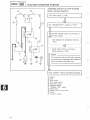
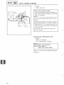
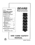
iLLUSTRATED SYMBOLS
(Refer to the imlustration)
Illustrated symbols (_ to _) are designed as
thumb tabs to indicate the chapter's number and
content.
_
ENG
I
Periodic
inspection and adjustment
General information
...............
[C_B
_il
_
_
Engine
Cooling system
_
_
Chassis
Carburetion
[CHAS_
_) ,_ppter
'ndaIces
®
_
6_)
@
@
@
@
(_
_=
_
Illustrated
_
(_) Filling fluid
the
specifications
(_ Lubricant
(_ Tightening
®
±
appearing
in the text.
Wear
Enginelimit,
speed
clearance
_
_
=
_
_
symbols (_ to (_ are used to identify
Illustrated
_,
=
_
(_
symbols
(_ to (_
in the exploded
diagram indicate grade of lubricant
of lubrication point.
(_ Apply engine oil
(_ Apply gear oil
_
Apply
Apply
(_ Apply
® Apply
(_ Apply
and location
molybdenum
wheel
bearing disulfide
grease oil
lightweight lithium-soap base grease
molybdenum disulfide grease
locking agent (LOCTITE ®)
_ii_iii_!i
_i_i__
iiiiii!i_i_,
i_i_!i_
_
_ __
!_i_i
i_i
ii_!_i_
_
_i_iii_i!iii
_I_
_
_i,_,_
....
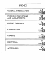
mNDEX
GENERAL
NFORMA'r oN
PERmODmC
INSPE
ONS
IJ]
AND ADJUSTMENTS
UNSP
ENGmNEOVERHAUL
_
ADJ
ENG
CARSUREYION
CAR8
CHASSMS
CHAS_
ELECTRICAL
ELEC
APPENDmCES
APPX
iilliii_iiiii_i_
_
_i_iiiii
_ii_i_i
_
__i_i_iiii_i!ili_
'
GEN
CHAPTER 1.
.........
......
GENERAL
mNFORMATiON
SCOOTER IDENTIFICATION
.......................................
VEHICLE IDENTIFICATION NUMBER ..............................
ENGINE SERIAL NUMBER .......................................
1-1
1-1
1-1
INPORTANT iNFORMATiON .......................................
ALL REPLACEMENT PARTS .....................................
GASKETS, OIL SEALS, AND O-RINGS ............................
LOCK WASHERS/PLATES AND COTTER PINS ....................
BEARINGS AND OIL SEALS .....................................
CIRCLIPS ......................................................
1-2
1-2
1-2
1-2
1-2
1=3
SPECIAL TOOLS ..................................................
FOR TUNE-UP ..................................................
FOR ENGINE SERVICE ..........................................
FOR CHASSIS SERVICE .........................................
FOR ELECTRICAL COMPONENTS ................................
1-3
1-3
1-4
1-8
1-8
I_
[ GEN
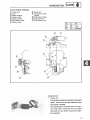
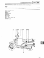
SCOOTER
iDENTiFICATION
GENERAL INFORMATmON
SCOOTER
VEHICLE
IDENTIFICATION
IDENTmF_CATION
NUMBER
The vehicle identification
number
h_to the steering head pipe.
_i_
NOTE:
The vehicle identification
_.-_is stamped
number is used to iden-
tify your scooter and may be used to register your
scooter with the licensing authority
in your state.
Starting
Seriam Number:
JYA1YA00_
HA000101
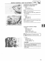
ENGINE
SERIAL
NUMBER
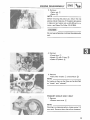
The engine sedaf number/1_ is stamped into the
elevated part of the left rear section of the transmission case.
NOTE:
The first three digits of these numbers
:
are for
model identifications; the remaining digits are the
unit production
number,
Starting
SeriaJ Number:
1YA-000101
NOTE:
Designs and specifications
without notice.
1-1
are subject to change
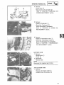
iMPORTANT iNFORMATiON
!ioE°
INFO
INPORTANT INFORMATION
ALL REPLACEMENT
PARTS
1. We recommend to useYamaha genuine parts
for all replacements. Use oil and/or grease
recommended by Yamaha for assembly and
adjustment.
GASKETS, OIL SEALS, AND O-RINGS
1. All gaskets, seals, and O-rings should be
replaced when an engine is overhauled. All
gasketsurfaces,oil seallips, and O-ringsmust
be cleaned.
....
2. Properlyoil allmating partsand bearingsduring reassembly. Apply grease to the oil seal
lips.
LOCK WASHERS/PLATES
TERPaNS
AND
COT-
1. All lock washers/plates (_ and cotter pins
must be replaced when they are removed.
Lock tab(s) should be bent along the bolt or
nut flat(s) after the bolt or nut has been
properly tightened.
300-000
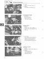
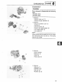
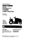
BEARINGS AND OiL SEALS
C3
1. Install the bearing(s) (_ and oil seal(s) (_
with their manufacturer's marks or numbers
=_
_
_/,_
300-002
letters must be on the side exposed to view.)
When installing oil seal(s), apply a light coating of light-weight lithium base grease to the
seal lip(s). Oil the bearings liberally when infacing outward. (In other words, the stamped
stalling.
Do not use compressed air to spin the bearings dry, This causes damage to the bearing
surfaces.
300-003
1-2
iMPORTANT
INFORMATION/SPECIAL
...................
TOOLS
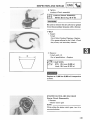
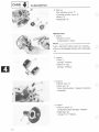
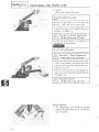
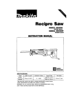
C_RCLIPS
fore reassembly. Always replace piston pin
clips after one use. Replace distorted circlips.
When installing a circlip _, make sure that
the sharp-edged corner _) is positioned opo-site to the thrust _} it receives. See the sec1. All circlips should be inspected carefully be-
/£_I_
30000!
U
_4_ tional
Shaft view.
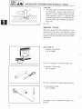
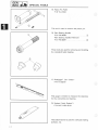
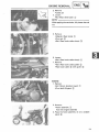
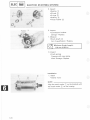
SPECIAL
TOOLS
The proper special tools are necessary for complete and accurate tuneoup and assembly. Using
the correct special tool will help prevent damage
caused by the use of improper tools or improvised
techniques.
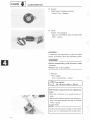
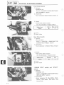
FOR TUNE UP
1. Inductive Tachometer
P/N YU_08036
This tool is needed for detecting engine rpm.
.....
2. Inductive Timing Light
P/ N YUo33277
This tool is necessary for checking ignition timing.
3. Compression
Gauge
This gauge is used to measure the engine com.pression.
i
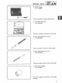
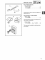
SPECIAL TOOLS
mNFOI - I
J GEN-r _ _]
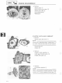
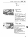
4. Fuel Level Gauge
P/N YM-01312-A
I
1
This gauge is used to measure the fuel level in
the float chamber.
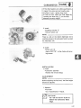
FOR ENGBNE SERVICE
1. Rotor Holder
P/N YU-01235
This tool is used to hold the flywheel magneto
when removing or installing the flywheel magneto
securing nut.
2 Flywheel Magneto Puller
P/N YM-01080
This tool is used for removing the flywheel
magneto.
3. Primary Sheave Holder
P/N YS-01880
This tool is used when holding the clutch hub.
4. Clutch Spring Holder
P/N YS-28891
This tool is used to dis-/re-assemble the secondary sheave.
1-4
blE
IGN_F_ J__
SPECmAL TOOLS
5. Clutch Compressor Holder
P/N YMo33285ol ....................
_
_ %:_b_
_i_
_
_
dary
sheave.
This tool
is used to dis-He-assemble the secon6, Locknut Wrench
P/N YM-04045-A
This tool is used to loosen or tighten the clutch
assembly securing nut.
7, #40 Torx Driver
P/N YU_29843o7
This tool is used to loosen or tighten the starter
wheel securing screw,
8. Valve Spring Compressor
P/N YM-04019
This tool is needed to remove and install the valve
assemblies.
9. Slide Hammer Set
P/N YU-01083
These tools are used to remove the rocker arm
and rocker arm shaft.
1-5
SPEO'A'TOOL
[OE°
i° O
10. Cylinder Gauge
........
_
P/N YU-03016
This tool is used to measure cylinder bore.
r=m
11. Valve Seat Cutter Set
P/N YM-91043
This tool is needed to resurface the valve seat.
12. Valve Guide Remover (7.0 mm)
P/N YM-01225
This tool is used to remove the valve guides.
13. Valve Guide Reamer (7.0 mm)
P/N YM-01227
This tool is used to rebore the new valve guide.
14. Valve Guide Installer
P/N YM-04017
This tool is needed to install the valve guides
properly.
1-6
[GEN_
JNFO__.__..__SPECIAL
TOOLS
...........
15, Piston Pin Puller
P/N YU-01304
@
_i_
This tool is used to remove the piston pin.
.....
@_
16. Plain Beanng Handle
P/ N YM-04058 ......................
Plain Bearing Installer/Remover
P/N YM-33297 ......................
_,)
LI_II/,
These tools are used for removing and installing
the crankshaft plain bearing
17. Plastigage ® Set "Green"
P/N YU-33210
This gauge is needed to measure the clearance
for the connecting rod bearing.
.......
18. Sealant (Quick Gasket® )
P/N ACCo11001-05_01
This sealant (bond) is used for crankcase mating
surfaces, etc,
IW
SPEC'ALTOO
lOE°
m° O
FOR CHASSIS
....
SERVICE
1. Ring Nut Wrench
P/N YU-01268 ......................
P/N YU-33975 ......................
(_
(_
These tools are used to loosen and tighten the
steering ring nut.
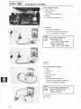
FOR ELECTRICAL COMPONENTS
1. Electro Tester
P/N YU-33260 ......................
(_
This instrument is necessaryfor checking the ignition system components.
2. Pocket Tester
P/N YU-33263 .... (_ or YU-03112 .... (_
This instrumentis invaluablefor checkingthe electrical system.
1-8
llLm
_
_
I/
_
_i_ii_i:i!_
_
q
i JNsPJ
ADJ |
1
.........
CHAPTER 2
PERiODiC INSPECTION AND ADJUSTMENTS
INTRODUCTION
..................................................
PERnOD_C MAiNTENANCE/LUBRICATION
.........................
ENGINE ...........................................................
CRANKCASE VENTILATION SYSTEM INSPECTION ................
FUEL LINE INSPECTION .........................................
INTAKE MANIFOLD INSPECTION ................................
EXHAUST SYSTEM INSPECTION ................................
IDLING SPEED
ADJUSTMENT
...................................
THROTTLE
CABLE
ADJUSTMENT
................................
ENGINE OIL LEVEL INSPECTION .................................
ENGINE OIL REPLACEMENT .....................................
OIL PRESSURE INSPECTION .....................................
V=BELT INSPECTION ............................................
TRANSMISSION OIL LEVEL INSPECTION ........................
TRANSMISSION OIL REPLACEMENT ............................
COMPRESSION PRESSURE MEASUREMENT .....................
CHASSIS ........................................................
REMOVING THE COVERS AND PANELS .........................
AIR FILTER ELEMENT CLEANING ...............................
FUEL COCK CLEANING ........................................
FRONT AND REAR BRAKE INSPECTION .........................
TIRE AND CAST WHEEL INSPECTION ...........................
FRONT WHEEL BEARING CHECK.. .............................
STEERING HEAD ADJUSTMENT ................................
REAR SHOK ABSORBER ADJUSTMENT .........................
CONTROL AND METER CABLES LUBRICATION ..................
BRAKE LEVER AND BRAKE PEDAL SHAFT LUBRICATION ........
CENTERSTAND AND SIDESTAND LUBRICATION .................
FRONT SHOCK ABSORBER LOWER PIVOT LUBRICATION ........
COMPRESSION ARM PIVOTS LUBRICATION ....................
FRONT AXLE AND ENGINE PIVOT SHAFT LUBRICATION .........
.......
ELECTRHCAL .....................................................
IGNITION TIMING CHECK ......................................
BATTERY INSPECTION .........................................
SPARK PLUG INSPECTION .....................................
BRAKE LIGHT SWITCH ADJUSTMENT ..........................
HEADLIGHT BULB REPLACEMENT ..............................
HEADLIGHT BEAM ADJUSTMENT ..............................
FUSE INSPECTION .............................................
2-1
2-1
2-3
2-3
2-3
2-3
2-3
2=4
2-4
2-5
2-5
2-8
2-8
2-9
2-9
2-10
2=12
2=12
2=14
2-15
2-16
2=17
2-20
2-20
2-21
2-22
2-22
2-22
2=22
2=22
2-22
2-23
2-23
2-25
2-27
2-28
2=28
2-29
2-29
LADj
LUBRmCATION
PERBODIC WNSPECTIONS
AND
ADJUSTMENTS
NTRODUCTION
This chapter includes all information necessary to perform recommended inspections and adjustments.
These preventive maintenance procedures, if followed, will ensure more reliable vehicle operation and
a longer service life, The need for costly overhaul
work will be greatly reduced.
This information
ap-
plies to vehicles already in service as well as new vehicles that are being prepared for sale, All service
technicians should be familiar with this entire chapter.
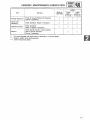
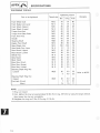
PERIODmC
MAINTENANCE/LUBR_CATION
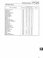
Item
unit:
Remarks
Break-in
1,000 (600)
Spark plug(s)
Check condition. Clean or replace if
necessary.
Air filter
Clean. Replace if necessary.
Crankcase filter
Clean. Replace if necessary.
Carburetor _
Check idle speed/starter
Adjust if necessary.
Fuel line*
Engine oil
Check fuel hose and vacuum pipe for
cracks or damage. Replace if necessary.
Replace (Warm engine before draining.)
O
Engine oil filter _
Replace.
O
Final gear oil (Sub
transmission oil)
Check oil level/oil leakage.
Replace every 24,000 (16,000) or 24 months.
Brake
operation.
O
km (milles)
6,000
12,000
(4,000) or
(8,000)
or
EVERY
6 months
12 months
(__
O
__,.F_
O
(b
O
O
L_
O
O
(_)
O
O
O
Check operation. Adjust if necessary.
©
O
V-belt
Check damage and wear. Replace if
necessary. Replace every 18,000 (12,000),
O
{}
Wheels _
Check balance/damage/runout,
Repair if necessary.
_i,,
_
Wheel bearings*
Check bearings assembly for looseness/
damage. Replace if damaged.
O
O
Steering bearing _
Check bearings assembly for looseness.
Correct if necessary. Moderately repack
every 24,000 (16,000) or 24 months. **
Bottom link pivots
and front axle
REPLACE
O
J
O
O
Apply grease lightly. *__
O
d,_
Front forks*
Check operation/oil leakage.
Repair if necessary.
O
_,_
Front shock
absorber lower
pivots
Apply until new grease shows. *_*
O
O
O
O
Rear shock
absorber*
2_1
Check operation/oil leakage.
i Repair if necessary.
....
...........
PERRODIC
MAre
NTENANCE/LU
B
RmCATmON
AD
J
EVERY
.........
Item
Break-in
1,000 (600)
6,000
(4,000) or
6 months
12,000
(8,000) or
12 months
Check all chassis fittings and fasteners.
Correct if necessary.
0
0
0
Check operation. Repair if necessary.
0
0
0
Sidestand switch*
Check operation.
Clean or replace if necessary.
0
0
0
Battery*
Check specific gravity. Check breather
pipe for proper operation.
Correct if necessary.
0
0
Fittings/Fasteners*
Center and
sidestand*
*"
**"
***:
Remarks
It is recommended that these items be serviced by a Yamaha dealer.
Medium weight wheel bearing grease.
Lithium soap base grease.
E4
2-2
CRANKCASE
ADJ
I_NSP]__j
VENTmLATION
SYSTEM
EXHAUST
SYSTEM _NSPECTION
UNE _NSPECTION/INTAKEMANIFOLD
INSPECTION/FUEL
_NSPECTION/
ENGINE
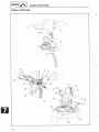
CRANKCASE
VENT_LATION
SYSTEM
INSPECTION
1. inspect:
oCteaner ioint hose _
oAir duct {Outlet) (_)
Cracks/Damage_-_ Replace.
_Spdng bands _}
Damage/Loose-_ Replace.
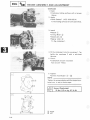
FUEL LiNE iNSPECTiON
1ohspect:
oVacuum hose (_}
Cracks/Damage--+
Replace.
oFuel
hose (_!_
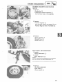
INTAKE MANRFOLD iNSPECTiON
1. Inspect:
olntake manifold _1_
_
......-.............
" '
'f\
_
_Carburetor joint _2}
_Gasket (htake manifold) (_
\
_'_
2. Tighten:
®Screw (Carburetor clamp) _
oBolts (Intake manifold) _5"_
_
10 Nm {1.0 m okg, 7,2_:ftoib)
Boit(,ntakeMan,fold)
@
EXHAUST
SYSTEM _NSPECTmON
1. Inspect:
_Gasket (Exhaust pipe) _i_
oMuffler assembly _
Damage _-_Replace.
2. Tighten:
6Socket bolt (Exhaust) _}
eFlange bolt (Muffler) _.4_
30 Nm {3.0 m okg, 22 ftoJb)
Range Bolt {Muffler) _4}}:
25 Nm {2.5 mokg. 18 ftolb}
Socket Bomt {Exhaust} @-_:
2_3
1
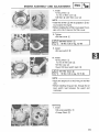
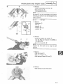
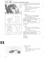
iDLiNG SPEED ADJUSTMENT/
THROTTLE CABLE ADJUSTMENT
mNSP]_
I
ADJ
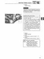
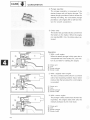
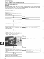
iDLiNG SPEED ADJUSTMENT
1. Remove:
o Front cover
Refer to "REMOVING THE COVERS AND
PANELS", page 2-12_.
2. Adjust:
eldle speed
Warm up the engine and turn the throttle
stop screw (_ to adjust.
Use the Inductive Tachometer (YU-08036).
- 1,350 r/rain
Idle1,250
Speed:
3_7 mm
(0.12 _0.28 inl
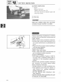
THROTTLE
NOTE:
IN
CABLE ADJUSTMENT
Before adjusting the throttle cable free play, the
engine idling speed should be adjusted.
1. Check:
oThrottle cable free play (_
Out of specification-_Adjust.
_
3-7 rnrn
(0.12-0.28
in)@:
Throttle
Cable
Free Play
]
2. Adjust:
oThrottle cable free play
Throttle cable adjustment steps:
eLoosen the adjuster lock nut _).
oTurn the adjuster (_ clockwise or counterclockwise until proper free play is attained.
oTighten the adjuster Iocknut (_.
NOTE:
After adjusting, turn the handlebars to right and
left and make sure that the engine idling does
not run faster.
2-4
ADJ
f lNSP]
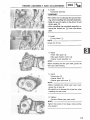
ENGtNE
ENGINE
OIL
REPLACEMENT
OraL LEVEL
MNSPECTION/
r,
ENGINE
OIL LEVEL
iNSPECTION
1. Remove:
®Front cover
*Side cover (Left) _
Refer to "REMOVING
PANELS",
THE COVERS AND
page 2q2.
2. Inspect:
\.
/
®Engine oil level
Oil level low-_Add
Engine
[
t
|'
!
/....
{2b___
oil leve_ inspection
I[
*Place the scooter
°
*Warm
I:1
sufficient
oil.
steps:
on a level place.
up the engine for serveral minutes, and
*Screw the dipstick _ completely out, and
stop it.
then just rest the dipstick in the hole.
NOTE:
@ ..........
_
Wake
afew minutes
until level settles before
checking.
*Pull up the dipstick,
whether
50
40
50
60°F
_} _" _
__
0
5
IO
,
15°C
or not it is between
and minimum
,1, m@
and inspect the oil level
maximum
@-}
level _3}.
proper level.
_
Recommended
oil:
*If the level is lower, add the oil up to the
_
At 5°C {40°F) or Higher @:
SAE 20W40 Type SE Motor Oil
At 15°C {60°F) or Lower _6_:
SAE 10W30 Type SE Motor
ENGINE
Engine
Oil
OIL REPLACEMENT
Oil RepJacement
{Without
OiJ Filter)
1. Warm up the engine for several minutes, then
place a receptacle under the engine.
2. Remove:
*Side
cover (Left)
Refer to "REMOVING
THE COVERS AND
PANELS",
page 2q3.
* Dipstick
_}
*Drain bolt
Drain the engine oil completely.
3. Inspect:
*Gasket
,
(Drain bolt)
_3_
Damage-+ Re pl ace.
4. Tighten:
[_
2%
43 Nm (4.3 mokg,
Drain Bomt:
31 ft,lb)
1
ENGINE
OIL
REPLACEMENT
AD
J
5. Fill
eCrankcase
At
Recommended
5°C (40°F) or Oil:
Higher:
SAE 20W40 Type SE Motor Oil
At 15°C (60°F) or Lower
SAE 10W30 Type SE Motor Oil
Periodic Oil Change:
1.0 L (0.88 imp qt, 1.1 US qt)
Do not allow foreign material
crankcase.
to enter the
6. Install:
®Dipstick
7. Inspect:
oOil leaks
®Oil level
oOil pressure
Refer to "OIL PRESSURE INSPECTION"
section.
Engine Oil Replacement (With Oil Filter)
1. Warm up the engine for several minutes, then
place a receptacle under the engine.
2. Remove:
®Side cover (Left)
Refer to "REMOVING THE COVERS AND
PANELS", page 2-13.
o Dipstick (_
o Drain bolt (_
Drain the engine oil completely.
3. Remove:
// /
oOil filter cover (_
oOil filter (_
2-6
__
C=..Gm.E
oral.EPLACEME.T
4. Inspect:
oGasket (Drain bolt) (1._
®O-dng (Oil filter cover} (_
Damage -+ Replace,
......
....
5, Install:
®Oil filter (New)
oOil filter cover
NOTE:
_ Drain bok
olnstall the oil filter 0.} with its projection (_ facing towards the engine.
®Before installing the oil filter cover, apply the engine oil to the O-ring on the filter cover.
6. Tighten:
Drain bolt
oBolt (Oil filter cover)
Drain Bolt:
43 Nm {4.3 m.kg, 31 ft,lb)
Bolt (Oit Fiffer Cover}:
10 Nm (1.0 m,kg, 7.2 ft,_b)
7. Fill:
oCrankcase
Recommended
:30
{
40
50
_
60°F
w _,_:)
(.2_-__ _
0
5
IO
15°C
OiJ:
At 5°C {40°F) or Higher
@:
At 15°C {60°F} or Lower _-_2"_:
SAE 10W30 Type SE Motor Oil
With OH Filter Replacement:
SAE 20W40 Type SE Motor Oil
1,1 L (0.97 imp qt, 1.16 US qt)
Do not allow
crankcase.
foreign
material
to enter the
8. Instalk
* Dipstick
9. Inspect:
-Oil leaks
oOil level
®Oil pressure
Refer to "OIL PRESSURE INSPECTION"
2-7
sect{on.
OiL PRESSURE INSPECTION/V=BELT
RNSPECTmON
I _NsP]
I_
I
OIL PRESSURE INSPECTUON
1. Remove:
eFront cover
Refer to "REMOVING THE COVERS AND
PANELS", page 2-12.
oAir bleed bolt (_
2. Start the engine and keep it idling for several
minutes.
3. Inspect:
cOil condition of the bleed hole
Oil flows out--Oil pressure is good.
No oil comes out--Oil pressure is bad.
If no oil comes out after a lapse of one
minute, turn off the engine immediately so
it will not seize.
4. Tighten:
®Air bleed bolt
[_
........
Nm (2.0
Air20Bleed
Bolt:m okg, 14 ftolb)
]
V-BELT INSPECTION
1. Remove:
oCheck plug (V-belt) _)
2. Inspect:
oV-belt (_
Crack/Wear/Chipping-_ Replace
Oil or grease adhered to the V=belt-_Check
the primary and secondary sheaves.
Refer to "CHAPTER 3. PRIMARY AND
SECONDARY SHEAVE" section.
3. Install:
oCheck plug (V-belt) (_
2-8
ADJ
[INSP
TRANSMmSSJON
TRANSMISSION
_]
OraL
ORL REPLACEMENT
LEVEL_NSPECTmON/
TRANSMiSSiON
O_L LEVEL _NSPECTION
1_Inspect:
_Transmission oil level
Oil level Iow-_+Add sufficient oil,
50
H
40
_m_..__._.,,,0
I
O
5
50
Transmission o# Jevel inspection stops:
oPlace the scooter on a level place:
oScrew the dipstick _i_ completely out) and
then just rest the dipstick in the hole.
®Pull up the dipstick, and inspect the oil level
whether or not it is between maximum _2-_
and minimum level [:3_
60°F
)
JO
t5°C
_®lfthetevet
level,
the oil up to theproper
_-_ _ [ Re
co islower,
m m end edadd
O iH:
_
At 5°C (40°F) or Higher (..ilb:
SAE 20W40 Type SE Motor OiN
At 15°C (60°F) or Lower (_2_9:
SAE 10W30 Type SE Motor Oi_
TotaW Amount:
0.2 L {0.18 Wrap qt, 0,21 US qt}
Do not allow foreign
transmission
case,
materia_ to enter the
TRANSMiSSiON
OIL REPLACEMENT
1, Remove:
Rear wheet assembly
Refer to "CHAPTER 5. REAR WHEEL_
REMOVAL" section,
2. Replace:
eTransmission oil
Transmission oit replacement steps:
ePbce a receptacle under the transmission
case,
eRemove the dipstick (_ and drain bott __2_
then drain the transmission oil completely,
_lnspect the gasket _3_on the drain bolt. If
damaged, replace it,
_lnstatl the drain bolt, then tighten the it.
2-9
....
....
......
TRANSMiSSiON
OIL REPLACEMENT/
COMPRESSION PRESSURE MEASUREMENT
......
RNSP]$
ADJ
18NmCl.8m:kg.13tt.lb._!__w
__
Drain Bolt:
eApply the oil to the proper level.
,_)
Recommended
At
5°C 140°F) orOil:
Higher:
SAE 20W40 Type SE Motor Oil
At 15°C (60°F) or Lower:
SAE 10W30 Type SE Motor Oil
Total Amount:
0.2 L (0.18 imp qt, 0.21 US qt)
olnstall
the"TRANSMISSION
dipstick and inspect
oil level.
Refer to
OILtheLEVEL
INSPECTION" section.
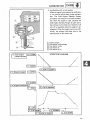
CONIPRESSION
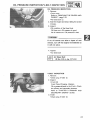
MEASUREMENT
....
PRESSURE
NOTE:
Insufficient compression pressure will result in
performance loss.
......
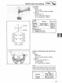
1. Warm up the engine, and stop it.
2. Remove:
®Front cover
Refer to "REMOVING THE COVERS AND
PANELS" section.
®Spark plug
3. Measure:
eCompression pressure
Compression pressure measurement steps:
elnstall the Compression Gauge (_ (YU33223).
oCrank over the engine with the electric starter (be sure the battery is fully charged) with
the throttle wide-open until the compression
reading on the gauge stabilizes.
oCheck readings with specified levels (See
chart).
2-10
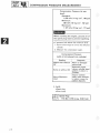
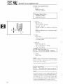
COMPRESSION
PRESSURE
MEASUREMENT
Compression
[eve[):
Pressure
{at sea
Standard:
1,079 kPa {11 kg/cm
Minimum:
981 kPa {10 kg/cm
Maximum:
2, 142 psi)
1,177 kPa (12 kg/cm
When
cranking
the engine,
2, 156 psi)
2, 171 psi)
ground
all of
®If pressure fails below the minimum level:
the spark plug lead te prevent sparking.
1. Squirt a few drops of oil into the affected
cylinder°
2. Measure the compression
Compression
(with
oh introduced
Reading
again.
Pressure
into
cylinder)
Diagnosis
Higher than without
Oil
Worn or damaged
pistonrings,
Same as without
Defective ring{s)
valves, cylinder head
gasket or piston is
possible.
Above
Level
Maximum
Oil
Inspect cyRinder
head, valve surfaces,
or piston crown for
carbon deposits.
4 install:
.........
....
oSpark plug
• Front cover
l
2-11
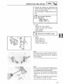
REMOVING THE COVERS AND PANELS
/_l
I iNSP
j_ADJ._!
CHASSIS
..........
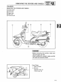
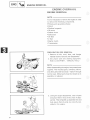
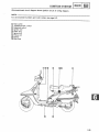
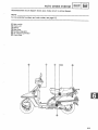
REMOVING THE COVERS AND PANELS
(_ Scooterpanel
(_ Fronttrunk
(_) Front cover
(_ Upper cover
(_) Side cover
(_) Footrestboard
!iil _ii_iiiiiiiii
eBefore removing the cover(s), make sure
that aft hooks are free.
®After installing the cover(s), make sure that
all hooks are securely fitted.
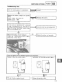
Front Cover
_S
__
2. Remove:
,.O0eot,,oso,.t.
*Front cover (_)
o oec,a,
scre
2-12
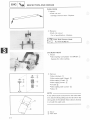
REMOVING
THE COVERS
AND
PANELS
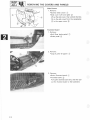
Side Covers
1, Remove:
-Screws (Side cover)
oSide cover (Left and right}
...........
_
z/
Lift up the side cover, then unhook the lobs
_3-_on the side cover from the receptacles
_4_in the upper cover _
Footrest Board
t. Remove:
®Bolt (Rear brake pedal) @
®Brake pedal @
.....
2, ®Caps
Remove:
(Lower _ Upper) _.
3. Remove:
eBolts (Footrest board) (9
®Footrest board @
Pull up the footrest board end, and then pull
out the footrest board to the backward.
/i _i_!i/i_
2-13
REMOViNGAI
R TH
EFI
LTERCOVERSELEM
ENTAN
DCLEANIPAN
ELS/NGI ADjmNSP
_(_L]
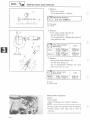
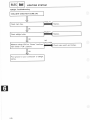
Front Trunk
1. Remove:
-Screws
oScrews (_ with clamps _)
2. ®ScrewseCapsRemove:(_(_
with clamps (_)
s-
3. Strip the side mold end (_.
4. Remove:
®Screw (Front trank) (_
oClamp _)
oFront trunk assembly
Scooter Panel
1. Disconnect:
®Flasher lead couplers _)
2. Remove:
®Bolts (Scooter panel) (_
®Screws (Scooter panel) (_
oScooter panel assembly
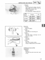
AiR FILTER ELEMENT CLEANING
1. Remove:
®Front cover
®Side cover (Left)
Refer to "REMOVING THE COVERS AND
PANELS" section.
oCover (Air filter case) (_
Remove the cleaner joint hose (_) from the
sheave case (_ at the same time.
2. Remove:
oElement
The engine should never be run without the
air filter element installed; excessive piston
and/or cylinder wear may result.
2-14
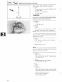
FUEL COCK CLEANING
AiR FmLTER ELEMENT CLEANING/
Air filter
e_ement cleaning
steps:
®Apply the Yamalube 2'cycie oil to the entire
surface of the element,
®Wrap the element with a clean rag; and
oSqueeze
the
element
dry.
*Wash
theout
airthe
filterexcess
element
squeeze
oit, with solvent.
The element should be wet but not be
__
dripping.
®Do not squeeze
•
....
:....
;:!i_:.
the emement
hard°
eAfter installing the element; make sure
oRepJaee
the element
if damaged;
it is positioned
correctly
in place:
,
A
;
3. Lightly grease the element sealing side for an
air-t!ght seal between the element and case.
4o Install:
.....
_Element (Rear) _
®Element (Front) _-}
eOomponents in above list (Step "1")
NOTE:
_
Install the rear element first,
.....
FUEL COCK CLEANING
1. Remove:
oFront cover
®Side cover (Left and right)
Refer to "REMOVING THE COVERS AND
PANELS" section,
2oTurn the fuel cock lever _'} to the "OFF".
3. Disconnect:
Fuel hose
oVacuum hose
4. Remove:
®Filter cup (.i_}
5, Place arec¢ptacb under the fuel cock, and
turn the fuel cock lever to the "ON", then
drain the fuel completely,
2q5
.....
FUEL COCK CLEANING/
FRONT AND REAR BRAKE INSPECTION
INSP
i_
i
ADJ
FUEL IS HIGHLY FLAMMABLE:
eAIways turn off the engine when draining.
=Take care not to spill any fuel on the engine
or exhaust pipemuffler when draining.
oNever drain fuel while smoking or in the vi=
cinity an open flame.
6. Remove:
e Fuel cock assembly
oFilter screen (_
7. oRubber
Inspect: gaskets
Damage -_ Replace.
8. Clean:
oFilter screen
oFilter cup
Clean it with solvent.
9. Install:
oFuel cock component parts
NOTE:
Be careful not to clamp the fuel cock too tightly
as this may unseat the rubber gaskets and lead
to a fuel leak.
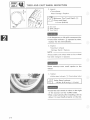
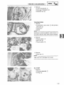
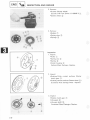
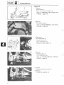
FRONT AND REAR BRAKE INSPECTION
Lining Inspecton (Front/Rear)
1, Activate the brake lever or brake pedal,
2. Inspect:
_Wear indicator (_
Indicator at wear limit line (_Replace
brake shoes.
Refer to "CHAPTER 5. FRONT WHEEL"
section.
[] Front
[] Rear
Front Brake Lever Free Play Adjustment
1. Check:
oFront brake lever free play _)
Out of specification-_Adjust.
u_
_'_
Front Brake Lever Free Play:
10-20 mm (0.4-0,8 in}
2-16
INSP
FRONT
TIRES
AND
AND
REAR
CAST
BRAKE
WHEEL
iNSPECTION/
_NSPECTION
2. Adjust:
Free play
Turn the adjuster _i_ until the free play is wi,thin the specified range,
NOTE:
After adjusting, check the operation of the brake
light.
Rear Brake Pedal Free P_ay Adjustment
1. Check:
®Rear brake pedal free play
_J
.............
Out of specification-+Adjust.
5_-15 mm {0.20-- 0.60 in)
Rear Brake Pedal Free Play:
[_
J]
2. Adjust:
®Free play
Turn the adjuster @ until the free play is within the specified range.
NOTE:
After adjusting, check the operation of the brake
light.
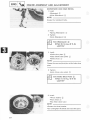
TIRE AND CAST WHEEL _NSPECTION
This scooter is equipped with cast wheels
designed for tubeless tires only,
Tubeless tires are installed
as standard
equipments.
1, Proper loading of your scooter is important for the handling, braking, and other
performance and safety characteristics of
your scooter NEVER OVERLOAD YOUR
SCOOTER, Make sure the total weight of
the accessories, etco do not exceed the
maximum moad limits, Operation of an
overJoaded scooter
could cause tire
damage,
2q7
an accident,
and injury.
TIRES AND
2. Improper
....
,°sPIJ
ADJ
CAST WHEEL INSPECTION
tire pressures
life and handling.
prior to each trip
greatly
affect
tire
Check tire pressures
and adjust properly if
necessary.
If tire pressures are too high, shocks from
the road wgl not be damped and will be
carried to the frame and handlebars, thus
adversely
affecting
riding comfort.
dition, scooter stability
making a turn.
If tire pressures
In ad-
wig be poor when
are too low, tires will
be
deformed
greatly, thus shortening
tire
life. When braking the wheels, tires could
slip over wheel rims and tire tubes could
broken. When turning the corner or the
curve, the scooter could easily turn over.
Always perform the following
operation,
service.
maximum
steps to ensure safe
tire performance,
and long
1. Measure:
oTire pressure
Use an air gauge
Out of specification-_Adjust.
Tire inflation
adjusted
equals
pressure should be checked
when
the temperature
the ambient
and
of the tire
air temperature.
Tire in-
flation pressure must be adjusted according
to total weight
of cargo, rider, passenger,
and accessories
approved
for this model),
Basic weight:
With oil and full
fuel tank
Maximum
Cold tire
pressure:
(fairing,
load _
Up to 90 kg
(198 Ib) load"
90
kg (198 Ib)Maximum
load"
saddlebags,
etc. if
and vehicle speed.
128 kg (282 Ib)
156 kg (343 Ib)
Front
Rear
147 kPa
196 kPa
(1.5 kg/crn 2, (2.0 kg/cm 2,
21 psi)
28 psi)
147 kPa
245 kPa
1.5 kg/crn 2, (2.5 kg/crn 2,
21 psi)
35 psi)
_Load is the total weight of cargo, rider, passenger, and accessories.
2-18
__
LLNSP 1
t ____
TIRES AND CAST WHEEL iNSPECTiON
2, Inspect:
eTire surfaces
Wear/Damage-_
Replace.
{Front
Rear}
Minimumarid Tire
Tread
1.0 mm {0.04 in)
_
Depth
_/:
(!_ Side wall
_2}_Wear indicator
_) Tread depth
_lf
wear indicator
to view,
e[t the
is dangerous
to ride (2)
withexposed
a wornout
tire,
replace
the tire
3. Inspect:
_Alumh_um
immediately,
wheels
Damage/BendsNOTE:
Always
balance the wheel when a tire or wheel
has been changed
Never
wheel
attempt
or replaced,
even
small
repairs
to
the
4_ Tighten:
_Valve stem Iocknuts
(J_ (Front wheel only)
1.5 Nm {0.15 mokg,
VaNve Stem Locknut:
_
elnsta]J the rear whee_ air valve
of the scooter
{on the muffler
e Ride conservativemy
allow
2-19
it to seat itself
1.1 ft*Jb}
on the right
side}.
after installing
property
q
a tire to
on the rim,
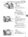
FRONT WHEEL BEARING CHECK/$TEERmNG HEADADjUSTMENT
IADJImNSP[
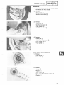
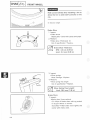
FRONT WHEEL BEARING
CHECK
1. Placethe scooter on its centerstand, then elevate the front wheel.
2. Check:
oFront wheel bearings
Spin the wheel by hand. Tuch the axle or
front fork while spinning the wheel.
Excessive vibration--, Replace bearings.
!
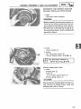
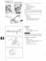
STEERING HEAD ADJUSTMENT
Steering
.........
......
.......
Head Inspection
vate the front wheel.
2.
1. Check:
Placethe scooter on its centerstand, then eleoSteering assembly bearings
Grasp the bottom of the forks and gently
rock the fork assembly back and forth.
Looseness-_Adjust.
H
Steering head adjustment steps:
eRemove the steering nut cover (_.
oLoosen the upper ring nut (_ completely, using the Ring Nut Wrench (YU-01268).
NOTE:
Set the Torque Wrench to the Ring Nut
Wrench so that they form a right angle.
oTighten the lower ring nut _) using the Ring
Nut Wrench (YU-33975).
"_
Ring Nut (_ (Initial Tightening):
30 Nm (3.0 mokg, 22 ftolb)
oLoosen the lower ring nut _
completely
and retighten it to specification,
Do not over=tightening.
3 Nm
mokg, Tightening):
2.2 ftolb)
Ring
Nut(0.3
_)(Final
eCheck the front fork by turning it lock to lock.
If there is any binding, remove the front fork
assembly and inspect the steering boll bearings and boll races.
Refer to "CHAPTER 5. FRONT FORK" for
more detaills.
2=20
ADJ I
INSPLI
REAR SHOCK
ABSORBER
ADJUSTMENT
STEERING
HEAD
ADJUSTMENT/
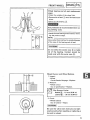
eHold the lower ring nut _'_ and tighten
the
upper ring nut (_-_using the Ring Nut Wrench
(YU-33975)
..........
__
kg; 22ft
l eTighten
_b/
ttie har, d,ebar securing bo,t
g,4s
_7
ft
e Reinstall
the steering
nut cover
_),
N
REAR
SHOCK
ABSORBER
ADJUSTMENT
1. Adiust:
®Spring
NOTE:
_.
preJoad
-
-- _
-
The spring pr@oad of the rear shock absorber can
be adjusted to suit dder's preferance, weight, and
the course conditions.
Spring pre_oad adjustment
steps:
oAdjust the sprinq prebad with the spring sea_
A _
h
A
_
r.
J
Stiffer
_
*_ncrease
the spring
Softer
_b_Decrease the spring preload.
(Turn
the _pr,n_
spring sea, seatC'ookw'se.,
counter°
_,Turn
the
c_ockwise.
Standard Position: B
Softest Position (Minimum
Stiffest Position (Ma×imum
#reload
Position}: A
Position_: E
Never attemp_ to turn the spring
yond the maximum
or minimum
2_21
seat beo
setting.
....
CONTROLANO
METEROABLESLUBR
BRAKEPEO
l I
LUBRICATION/CENTERSTAND
AND SIDESTAND LUBRICATION/FRONT
SHOCK ABSORBER
LOWER PIVOT LUBRICATION/COMPRESSION
ARM PIVOTS LUBRICATION/
FRONT AXLE AND
ENGINE
PIVOT
SHAFT
LUBRICATION
_NSP
ADJ
CONTROL AND METER CABLES
LUBRICATION
Lubricate the inner cable and cable end.
[_]
SAE 10W30 Motor Oil
amaha Chain and Cable Lube or
BRAKE LEVER AND BRAKE PEDAL SHAFT
LUBRICATmON
Lubricate the pivoting parts of the brake lever and
pedal shaft.
SAE 10W30 Motor Oil
.......
_
YamahaChainandCabieLubeor
CENTERSTAND AND SiDESTAND
LUBRICATION
Lubricate the centerstand and sidestand at their
pivot points.
SAE 10W30 Motor Oil
Yamaha Chain and Cable Lube or
.......
........
FRONT SHOCK ABSORBER LOWER PIVOT
LUBRICATION
Apply the grease from nipple on the compresion
arm until new grease comes out.
_
Lithium Soap Base Grease
COMPRESSION ARM PIVOTS
LUBRICATION
Lubricate the pivoting parts of the compression
arm.
_
Lithium Soap Base Grease
FRONT AXLE AND ENGINE PIVOT SHAFT
LUBRICATION
Lubricate the front axle and engine pivot shaft.
I_
Lithium
Soap Base Grease
2-22
_
IGNIT{ON TmMING CHECK
ELECTRICAL
i
/
/
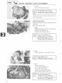
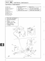
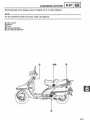
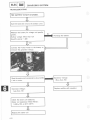
_GNITIION TIMING CHECK
1, Remove:
eFront cover k_i_)
*Side cover (Left and right} _2_)
o Footrest board
Refer to "REMOVING THE COVERS AND
PANELS" section.
2, Remove:
aPassenger footrest (Right} _,)
3, Remove:
oSocket bolts (Exhaust pipe}
oF_ange bolts (Muffler) (_21}
eMuffler assembly
4, Remove:
®Screws lAir shroud I) _-}
Screws (Fancase cover}
_Air shroud 1 (_ with fancase cover @
5. Install:
Muffler assembly
When check{rig the ignition timing,
fief must be installed in placeo
2-23
the muf ....
UGNmONTiMiNGCHECK ImNsP
ADJ
]
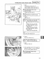
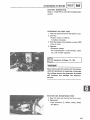
6. Check:
........
oIgnition timing
The ignition timing is adjusted for maximum
performance at the factory. DO NOT attempt
to change this setting,
ignition timing check steps:
®Connect the Timing Light (_ (YU-33277) to
.....
®Warm up the engine, and keep the engine
the spark plug wire.
running at the specified idle speed of 1,300
r/min.
Use the Inductive Tachometer
(YU-08036) to check the engine speed.
oVisually check the stationary pointer (_) on
the crankcase to verify it is within the required
firing range (_) indicated on the flywheel.
Incorrect firing range-* Check flywheel and/or
pickup assembly (tightness and/or damage).
Refer to "CHAPTER 6. ELECTRICAL" for further information.
.....
7. Remove:
eMuffler assembly
8. Install:
oComponents in above list (step "4-1")
9. Tighten:
oComponents in above list (step "3 and 2")
25 NmBolt
(2.5(Muffler):
mokg, 18 ftoib)
Flange
Socket Bolt (Exhaust Pipe)
30 Nm (3.0 m,kg, 22 ft=lb)
Bolt (Passenger Footrest):
25 Nm (2.5 m okg, 18 ftolb)
2-24
___
JNSP
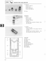
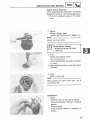
BATTERY
NSPECT ON
BAKERY
INSPECTHON
1. Inspect:
_Battery
fluid level
Battery fluid Jevel Iow-_Fill°
Fluid level should be between
lower level marks.
upper and
(_'_ Upper leveJ
Lower level
Refill
with
contains
water
minerals
Battery
sulfuric
highly
distilled
onmy; tap water
harmful
to a battryo
e_ectroiyte
is dangerous;
it contains
acid and therefore
is poisonous
and
caustic.
AJways
follow
these
preventive
measures:
oAvoid bodiay contact
with electroUyte
can cause severe burns or permanent
....
as it
eye
injury.
®Wear protective
working
Antidote
eye gear when
with
®EYES--Flush
with
water.
water
for 15 minutes
get immeditate
medical
Antidote
(iNTERNAL}:
large quantities
tow with
milk
vegetabJe
tention.
oil
Batteries
of water
of magnesia
Get
_Charge
batteries
e Keep batteries
lighted
flames
away
{e,go,
2.-25
medicaJ
explosive
SMOKE
from
at o
hydrogen
always
fire,
welding
follow
area.
sparks,
or
equipment,
etco}
when
d_ing batteries .......
KEEP BATTERIES
AND
OF REACH
egg, or
in a weH-ventiHated
cigarettes,
®DO NOT
or mimk foF
beaten
immediate
also generate
and
attention°
gas, therefore
you shouH
these preventive
measures:
open
or
near batteries,
(EXTERNAL):
®SKmN--Nush
eDrink
handling
charging
or han.o
ELECTROLYTE
OF CHILDREN,
OUT
BATTERY iNSPECTION I INSPI
ADJ
1
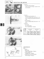
2. Remove:
............
oBattery
NOTE:
Disconnect the negative lead farst.
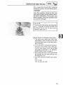
3. Inspect:
oBattery fluid specific gravity
Out of specification-_ Charge.
Always charge a new battery before using
it to ensure maximum performance.
Charging Current: 1.0 amps/10 hrs
Specific Gravity: 1.280 at 20°C (68°F)
4. Install:
e Battery
NOTE:
Connect the positive lead farst.
5. Inspect:
o Breather hose
Obstruction _ Remove.
Damage-+ Replace.
6. Connect:
eBreather hose
........
Be sure the hose is properly attached and
__
Whenrouted.
inspecting
the battery,
be sure the
breather hose touches the frame or exits in
such a way as to cause battery electroRyte
or gas to exit onto the frame, structural and
cosmetic damage to the scooter can occur.
(_ Battery
(_) Clamp
(_) Breather hose
2-26
[uNsP
] SPARK
PLUG mNSPECTmON
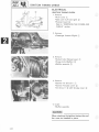
SPARK PLUG WNSPECTION
1. Inspect:
_Spark pkJg type
lncorrect-_ Replace.
.....
Standard Spark Ptug:
DPR7EAo9 {NGK}
X22EPRoU9 {NOD,}
2. Inspect:
o Electrode _'}
olnsuJator color _)
Normal
condition Replace.
ksa medium to tight tan
Wear/Damage-_
color.
Distinctly different color -_ Check the engine
('_
conditions
3. Clean:
eSpark plug
CIeanthe spark plug with a spark plug clean-.
er or wire brush.
4. Measure:
_Spark pkJg gap (a}
Out of specification-_Regap.
Use a wffe gauge.
E_
0,8--0o9 mm {0,031-_,0°035 in)
spark P'ug Gap /ka_:
1
5 Tighten:
eSpark Plug
.....
NOTE:
Before installing a spark plug, clean the gasket
surface and plug surface.
17.5 P_ug:
Nm {1.75 mokg, 12.5 fto_b)
Spark
]
NOTE:
If a torque wrench is not available when you are
installing a spark plug, a good estimate of the cor o
rect torque is 1/4 to 1/2 turns part finger tight.
Have the spark plug torqued to the correct value
as soon as possible with a torque wrench.
2-27
HEADLIGHT
BULB ADJUSTMENT/
REPLACEMENT
BRAKE
LIGHT SWITCH
ADJ
[INSPI_
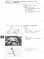
BRAKE LIGHT SWBTCH ADJUSTMENT
..........
1. Adjust:
®Brake light operating timing
Hold the main body (_ of the switch with
your hand so that it does not rotate, and turn
the adjuster (_) until the operating timing is
correct.
HEADLIGHT
1. Remove:
BULB REPLACEMENT
®Bolts (Headlight unit) (_)
2. Remove:
®Headlight unit (_)
3. Disconnect:
®Connecter (Headlight lead) (_)
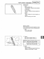
4. Remove:
oRubber cover (Headlight bulb)
oBulb holder (_
While pushing the bulb holder (_, turn it
counterclockwise
5. Remove:
o Bulb (_
Do not touch headlight bulb when it is on as
the bulb generates enormous heat; keep
flammable objects away.
2-28
[[_SP
]-_---]
HEADUGHT
BULB REPLACEMENT/HEADLIGHT
BEAM ADJUSTMENT/FUSE
INSPECTION
6. Insta!k
®Bulb (New)
NOTE:
(_}
Make sure the projections
_-2.._
on the bulb flange
are meshed with the slots _3} on the bulb case
@.
7. tnstalk
®Components
above list (Step "4--1")
& Adjust:
o Headlight
beam
Refer to following
HEADLIGHT
BEAM
section.
ADJUSTMENT
1o Adjust:
®Headlight
beam (Horizontally)
HorizontaJ
Ii Right
I Turn .....
Adjustment
screw(_
c-iockwise
e
2. Adjust:
oHeadlight
beam (Vertically)
Vertica_ Adjustment
.igher[ 7urno¢osting
sc-;ew
® clookwise
Lower
|
....
_un_ercBocKwlse
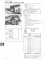
FUSE
INSPECTRON
1. Open the seat
2. Remove:
o Battery
cover
3. Inspect:
e Fuse (i_
Defective-_ Rep!ace,
Blow fuse (new)_-_ Inspect circuit.
(_) Spare fuse
2-29
....
FUSE INSPECTmON I INSP
ADJ
NOTE:
........
Install new fuses of proper amperage.
Description
IVlain
Reserve
Amperage
20A
20A
Quantity
1
1
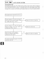
Blown fuse replacement steps:
eTurn off ignition and the circuit.
olnstall a new fuse of proper amperage.
®Turnon the switches and see if the electrical
®Fuse interrupts the circuit again-* Check elecdevicesystem.
operates.
trical
Refer to "CHAPTER 6. ELECTRICAL" for further information.
2-30
i_i_i_i
__i/_
_i__i_ii_i_ii_
_
2_31
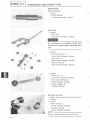
CHAPTER 3
ENGINE OVERHAUL
........
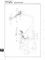
ENGINE REMOVAL ...............................................
PREPARATION FOR REMOVAL ..................................
BATTERY LEAD ................................................
AIR CLEANER CASE ............................................
CARBURETOR HOSES ..........................................
CONNECTORS ..................................................
CONTROL CABLES .............................................
ENGINE ........................................................
CARBURETOR AND INTAKE MANIFOLD .........................
MUFFLER ......................................................
FANCASE COVER AND AIR SHROUD ...........................
3-1
3-1
3-2
3-2
3-3
3-3
3-3
3-4
3-5
3-5
3-5
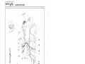
ENGINE DISASSEMBLY ...........................................
CYLINDER HEAD COVER AND CYLINDER HEAD .................
3-6
3-6
CYLINDER AND PISTON ........................................
PRIMARY SHEAVE AND V-BELT ................................
CLUTCH HOUSING AND SECONDARY SHEAVE ..................
FLYWHEEL MAGNETO AND STARTER MOTOR .................
REAR WHEEL AND MAINSTAND ...............................
STARTER CLUTCH AND CAMSHAFT ...........................
TRANSMISSION ...............................................
OIL PUMP ....................................................
CRANKCASE AND CRANKSHAFT ..............................
INSPECTION AND REPAIR ......................................
CYLINDER HEAD COVER, ROCKER ARMS AND ROCKER
ARM SHAFTS .................................................
PUSH RODS ..................................................
CYLINDER HEAD ..............................................
VALVE, VALVE GUIDE AND VALVE SEAT ......................
CYLINDER ....................................................
PISTON, PISTON RING AND PISTON PIN ......................
HYDRAULIC VALVE LIFTER ....................................
PRIMARY SHEAVE ............................................
SECONDARY SHEAVE .........................................
V-BELT .......................................................
STARTER CLUTCH AND IDLE GEAR ...........................
CAMSHAFT ...................................................
TRANSMISSION ...............................................
OIL PUMP ....................................................
BALANCER WEIGHT ..........................................
CRANKSHAFT,
CONNECTING ROD AND CRANKCASE ..........
3-7
3-8
3-9
3-10
3-10
3-11
3-12
3-12
3-13
3-14
3-14
3-17
3-17
3-18
3-26
3-26
3-28
3-32
3-34
3-38
3-38
3-40
3-41
3-42
3-43
3-44
__
IE"GI%
ENGINE ASSEMBLY
AND ADJUSTMENT
........................
CRANKSHAFT AND CRANKCASE .............................
TRANSMISSION ...............................................
CAMSHAFT AND STARTER CLUTCH ...........................
MAINSTAND AND REAR WHEEL ...............................
STARTER MOTOR AND FLYWHEEL MAGNETO .................
SECONDARY AND PRIMARY SHEAVES ........................
CYLINDER AND PISTON ......................................
CYLINDER HEAD AND CYLINDER HEAD COVER ................
ENGINE MOUNTING ...........................................
3-50
3-50
3°51
3-55
3-57
3458
3-59
3-.62
3-*63
3-67
i
....
_i!iiiiiiiiiJ>
ENG
ENGINE
REMOVAL
ENGmNE OVERHAUL
ENGmNE REMOVAL
NOTE:
it is not necessary to remove the engine in order
to remove the following
components.
oPdmary
_Clutch
sheeve
and secondary
o Flywheel magneto
_OH pump
e Starter motor
®Carburetor
oOil filter
oV--Bett
e Starter
clutch
eTransmission
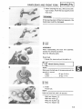
PREPARATION
t. Remove
matedat
FOR REMOVAL
all dirt,
mud,
before removal
2. Use proper
dust,
and disassembly,
tools and cleaning
Refer to CHAPTER
and foreign
equipment.
1, "SPECIALTOOL,"
NOTE:
When disassembling the engine, keep mated parts
together.
This includes gears, cylinders,
pistons,
and other parts that have been "mated"
through
normal wear, Mated parts must be reused as an
r_)
,
-<_
assembly
or replaced o
3, During the engine disassembly,
clean all parts
and place them in trays in the order of disas-_
sembly. This will speed up assembly time and
help assure that all parts are correctly
stalled in the engine,
3_1
rein--
E°O,OE
°EOOVAL
I0°Oi .l
4. Remove:
oFront cover (_
®Side covers (Left and right) (_
COVERS AND PANELS" section.
Refer to "CHAPTER 2 REMOVING THE
......
5. Remove:
oDipstick (Crankcase) (_)
®Drain bolt (Crankcase) (_
Drain the engine oil completely.
Refer to "CHAPTER 2. ENGINE OIL
REPLACEMENT" section.
H
6. Remove:
eDipstick (Transmission case) (_
oDrain bolt (Transmission case) (_
Drain the transmission oil completely.
Refer to "CHAPTER 2. TRANSMISSION
OIL REPLACEMENT" section.
.....
BATTERY LEAD
1. Remove:
oBridge plate (_
eCover (_)
2. Disconnect:
eBattely leads
NOTE:
Disconnect the negative lead (_ first.
AiR CLEANER CASE
1. Remove:
®Screws (Air cleaner case) (_
oBreather hose (Crankcase) (_
3-2
t
ENGL%_ ENG_NEREMOVAL
2. Loosen:
3
*Screw (Carburetor-clamp)
Remove:
_)
*Air
_
cleaner case assembly
CARBURETOR
HOSES
1. Dbconnect:
* Fuel feed hose _'}
*Vacuum hose (_$}
From fuel cock side.
CONNECTORS
1 Remove:
*Starter
motor
lead (Positive)
®Starter
motor
lead (Negative)
o Band
".2-}
"3"}
2o Disconnect:
_AC magneto
lead connecter
_Pickup
coil lead connecter
*Choke
unit lead coupler
®Oil level switch
CONTROL
(.!}
{_
{3"}
lead couple_
_4_
CABLES
1. Loosen:
Looknut
2. Remove:
f Throttle
cable adjuster}
*Throttle
came {_
From carburetor side,
*Spark
3_3
plug cap {3".
0_'}
E°O,OE.EMOV
[EO0
oCotter pin
4. Loosen:
eNut (Rear wheel axle) (_)
3. Remove:
NOTE:
Whileapplying
therearbrake,
fully
loosentheaxle
nut.
5. Remove:
oAdjuster (Rear brake) (_
oPivot pin (_)
oBolt (Rear brake cable-clamp) _)
6. Loosen:
®Bolt (Rear brake cable-clamp) (_
7. Remove:
oBolt (Rear brake cable-guide) (_
®Rear brake cable (_ with guide _)
ENGINE
1. Remove:
oBolt (Shock absorber-lower) _)
®Pivot shaft (Engine) _)
2. Remove:
®Frame assembly (_
From the engine assembly
3. Place the frame assembly (_ on a suitable
stand (_).
3-4
E_--_
ENGINE
REMOVAL
CARBURETOR AND iNTAKE MANIFOLD
1, Loosen:
*Screw (Carburetor_ctamp)@
2, Remove:
*Carburetor assemby _)
3. Remove:
*Clamp plate (Heat protecter) _}
* Heat protecter (2}
4. Remove:
_lntake manifold _i_ with O-ring _
MUFFLER
1 Remove:
*Socket boJts (Exhaust pipe) _
*Flange bolts (Muffler)
-Muffler assembly (_ with gasket
FANCASE COVER AND AmR SHROUD
1. Remove:
Fancase cover _1_
*Air shroud 1 F2
*Air shroud 2 _3"_
3_5
ENGINE
REMOVAL//ENGINE
DISASSEMBLY
I ENG
_J
2. Remove:
oOil level switch lead (_
From the lead guide
oAir shroud 3 (_
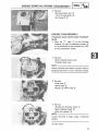
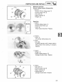
ENGINE DISASSEMBLY
CYLINDER HEAD COVER AND CYLINDER
HEAD
1. Align the "T" mark (_ on the flywheel
magneto (_ with the stationary pointer _)
on the crankcaseso that the pistonisat TDC
on the compression stroke.
2. Remove:
oBolts (Cylinder head cover)
oCylinder head cover
NOTE:
Follow numerical order shown in photo. Start by
looseningeach bolt 1/2 turn until all are loose.
3. Remove:
e Push rods (_
o Dowel pins (_)
o Nozzle (_) with O-ring _)
J
4. Remove:
.......
oSocket bolt (Cylinder head) (_)
oBolts (Cylinder head) (_)
oStay (Air shroud) (_)
NOTE:
Loosen the bolts in stage, using a crisscross
....
pattern.
i
(_ With washer
3-6
ENG
ENGINE
DmSASSEMBL¥
5_ Remove:
.....
_cylinder head assembly _,
Tap tightiy the cylinder head sOiid points with
a soft.head hammer to remove the cylinder
head°
NOTE:
if it is necessary to pry the cyJinder head loose
from the gasket, carefully use a broad, flat,-Made
screw driver atthe reinforced points _), shown.
_.
....
& Remove:
....
_Gasket (Cylinder head} @
"Dowei pins 0_)
_NoZZle {_) with oil seal ":"
.......
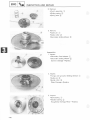
CYUNDER
AND P_STON
I, RemOve:
Socket bolts (Cy!inder) _{19_
,Cy!in_er _) with O_r '_g _
Tap !ightly the cylinder Solid points with a
soft--head hammer tO remove the cylinder.
2, Remove:
ePiston pin clip (_!_}
NOTE:
Before removing the piston pin clip, cover the
crankcase with asCleanrag Soyou will not acciden_
tally drop _he Nip into the crankcase°
3_7
....
Eoo,°0
o,sAssEooLy
[E°o
"*'1
3. Remove:
......
oPiston pin (_
oPiston (_)
NOTE:
Before removing the piston pin, deburr the clip
groove and pin holearea. If the piston pin groove
is deburred and piston pin is still difficult to remove, use Piston Pin Puller (YU-01304).
Do not use a hammer to drive the piston pin
out.
4. Remove:
oDowel pins (_
oNozzle (_) with O-ring (_
eGasket (Cylinder) (_)
5. Remove:
.........
oValve lifter (Intake _
NOTE:
and Exhaust (_)
Put marks on them so that they can be identified
as "intake" and "exhaust".
.....
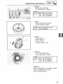
PRIMARY SHEAVE AND V=BELT
1. Remove:
oSheave case cover (_
NOTE:
Working in a crisscross pattern, loosen screw 1/4
turn each. Remove them after all are loosened.
3-8
E o,oE
O,SASSEMOL
2.Remove:
oDowel pins (_
* Gasket (Sheave case cover) (_2
_)
......
3, Straighten:
*Tab (Lockwasher)@
4. Remove:
*Nut (Primary sheave assembly} _2)
Use the Roter Holder (YU@1235) @_
* Lock washer {_)
*Primary fixed sheave (_}
* V-.belt @
5_ Remove:
*Primary slidhlg sheave (_-'1}
with collar _2_
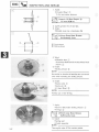
CLUTCH HOUSING
AND SECONDARY
SHEAVE
1: RemoVe:
_Nut (Secondary sheave} ,_!)
Use the Sheave Holder (YS-01880) [)}.
oCnteh
ho_sing
@
2. Remove:
*Secondary sheave assembly (,!"_
3-9
....
ENGUNEDnSASSEMBLY
ENG
......
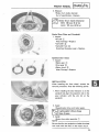
FLYWHEEL MAGNETO
MOTOR
1. Remove:
AND STARTER
_Cooling fan
oFlange bolt (Flywheel magneto) (_
Use the Roter Holder (YU-01235) _.
2. Remove:
eFlywheel magneto (_
Use the Rotor Holder (YU-01235) (_ and
Flywheel Magneto Puller (YU-01080) (_).
3. Remove:
oStator assembly (_
oWoodruff key (_
eStarter motor (_)
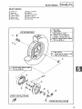
REAR WHEEL AND IV]AINSTAND
1. Unhook:
eSpring (Mainstand) (_
2. Loosen:
®Bolts (Mainstand) (_)
NOTE:
Do not remove the bolts (Mainstand) yet.
3. Remove:
eNut (Rear wheel axle)
oRear wheel (_
oThrust washer (_
3-10
E°o
I,..l0°o,,0
o,sAssEooL
4. Remove:
_Brake shoes _}
..-.
eBolts (Brake shoe ptate} (.2)
...........
eBrake shoe plate {_
o Bolts (Mainstand)
e Mainstand
.... .....
i ;}}!3nii!_
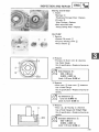
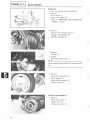
STARTER
CLUTCH
t. Remove:
_Starter
NOTE:
AND
CAMSHAFT
gear case cover @
_ _...........
Working in a crisscross pattern, loosen screw 1/4
turn each, Remove them after all are ioosened_
(_
o Dowet pins (._'_
_Gasket
(3!)
2, Remove:
eStarter
clutch
assembly
idler gea r (Starter
eShaft
{i.}
motor)
_}
(Idler gear) (.3
3. Remove:
®Camshaft
NOTE:
When removing
assembly
_)
o
the camshaft
knock pin _2) to the camshaft
3-11
assembly,
fit the
driven gear @}
ENGgNE D SASSEMBLY
ENG I
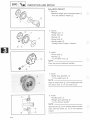
4. Remove:
+O-ring (Crankshaft) (_)
oDrive gear (Camshaft) (_
+Woodruff key (_
TRANSMISSION
1. Remove:
....
......
oTransmission case cover (_ with primary
drive axle (_
oDowel pins
oGasket
NOTE:
Working in a crisscross pattern, loosen screw 1/4
turn each. Remove them after all are loosened.
2. Remove:
oThrust washer (_
,Main axle (_
eThrust washer (_
3. Remove:
oDrive axle (_
NOTE:
Take care not to damage the oil seal.
OIL PUMP
1. Remove:
+Oil pump assembly (_
+O-rings (_)
3-12
EN__@_
ENGINE
DMSASSEMBLY
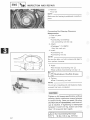
CRANKCASE
1. Remove:
AND CRANKSHAFT
+Botts (Oit filier case) (_)
+Guard (Oit revel switch lead)
+0[t filler case (3.)
2. Remove:
+Oit level switch (1_
3. Remove:
+OiLfilter C0ver (!-_
+oil
4. Remove:
+Screws {Crankcase) _++_
NOTE:
............
RemoVethe screws staging with the highest numbered one, in two steps,
(_)
@
_@
3+13
+
[_
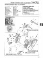
F_] R+GHT
LEFT
ENGmNE
DISASSEMBLY/INSPECTION
AND
REPAIR
_._
_J
6. Separate:
oCrankcase 1 (_ and 2 (_)
While tapping the crankcase 2 with a softhead hammer.
7. Remove:
eSpacer collar
8. Remove:
,
_;
eBalancer weight assembly
oCrankshaft assembly (_)
e Dowel pins (_)
oNozzle (_ with O-ring (_
E]i
9. Remove:
®Oil strainer (_
oRelief valve (_)
INSPECTHON
AND REPAUR
CYLINDER HEAD COVER, ROCKER ARMS
AND ROCKER ARM SHAFTS
1. Remove:
eRocker arm shafts (_
Use the Slide Hammer Set (YU-01083) (_)
and (_).
_'>
ii.
cRocker arms @
eWave washers (_
ePlate washers (_)
NOTE:
Identify each rocker arm and rocker arm shaft position very carefully so that it can be reinstalled
in its original position.
3-14
_N__®_
INSPECTION
AND
REPAIR
2. Inspect:
oCytinder head cover warpage
Use a surface plateo
Warp-+ Resurface,
Place a 400,--600 grit wet sandpaper on the
surface plate, and resurface the head using
a figureoeight sanding pattern,
NOTE:
Rotate the head several times to avoid removing
too much materiat from one side.
3. Inspect:
®Rocker arms
o Rocker arm shafts
Wear/Damage-....v+
Replace o
.......
_
Rocker arm shaft and arm inspection
steps:
®Inspect the two areas on the rocker arm for
1) Rocker arm shaft hole (-i._
signs of unusual wear.
2) Camqobe_contact surface (2-_
Excessive wear_e Replace,
®Inspect the surface condition of the rocker
arm shaft
....
_
_
Pitting/Scratches/Blue
discoBoration-* Re_
pJace/Check lubrication.
®Inspect the oil passages of the rocker arm
shaft,
Ctogged / Damage-+ Clean or replace
NOTE:
Always use a new O_ring, If rocker arm shaft
is removed°
oMeasure the inside diameter (_(_of the rock_
er arm holeo Use the Bore Gauge.
Out of specification---_Replace.
[_
12,000
Rocker
Arm_ 12,018
Inside mm
Diameter
{0,472 _ 0,473 in)
®Measure the outside diameter _ of the rocker arm shaft, where the rocker arm rides.
Use the Micrometer.
Out of specification -_Reptace,
Arrn Shaft Outside
Diameter
11,976 _ 11,991 mm
{0,471 _ 0,472 in}
3.-15
,OSPEOT,O°
AO0
OEPA,°
I
oCalculate the clearance by subtracting the
rocker-arm-shaft outside diameter from the
rocker-arm inside diameter.
.......
Out of specification _ Replace either or both
parts.
(Standard):
Arm=to-shaft Clearance
0.009 - 0.042 m m
(0.0004- 0.0017 in)
4. Apply:
®Rocker arm inner surfaces
oRocker arm shaft outer surfaces
oWave wahsers
®Plate washers
5. Install:
__
_
*Wave
washers (_)
@
ePlate washers
e Rocker arm shafts (_
_(___._
.Rocker arms @
NOTE:
The rocker arms are consist of intake (_ and exhaust (_) parts. Make sure they are installed to
correct positions.
........
!//_iii
....
NOTE:
oThe rocker arm shaft should be installed so that
the threaded portion faces outward.
.... .......
......
......
eThe hole @ in the rocker arm shaft should be
aligned with the hole (_) in the cylinder head
cover.
*Be careful not to damage the O-ring @ during
the installation of rocker arm shaft.
3-16
ENG
INSPECTION
AND
REPAIR
PUSH
RODS
1° Inspect:
oPush rod end
___
Damage/Uneven
wear -+ RepLace.
P
2o Measure:
,Push
rod runout
Out of specification
--_Replace.
0.3 Rod
mm {0.012
Push
Runout in)Limit:
_
CYLINDER
1, Attach:
,Valve
q
HEAD
Spring
Compressor
(YU-04019)
kl/rW_
Depress the valve springs.
2. Remove:
J"
_
---(_!
,Valve
_/_"
(i}
-VaLve spring seat (Upper)
.........
_)
,VaLve spring
"0ii
--
retainers
{7_0
_)--_§}
...........
@
....../
_
(Outer)
(2_
[3_}
seal (_}
-Valve
spring seat (Lower)
,Valve (_}
,Valve spring
NOTE:
(Inner)
If any deformation
is occurred
@
(]_
on the valve stem
end, deburr before pulting out the valve from the
valve guide on the cylinder head. Use an oil stone
to srnooth the stem end.
/
_
3-17
Deburr
Valve stem
,°s o°Ao°°EPA,°
[
3. Eliminate:
oCarbon deposit
Use rounded scraper, and wire brush.
NOTE:
.....
Do not a sharp instrument and avoid damaging
or scratching"
oSpark plug threads
eExhaust port
oCombustion chamber
.......
4. Measure:
eCylinder head warpage
Use a Straightedge (_ and Feeler Gauge
®.
Under specification--, Resurface.
Outer specification--, Replace.
.....
[_
Less than 0,025 rnm (0,001 in)
Cylinder Head Warp Limit:
VALVE, VALVE GUIDE AND VALVE SEAT
(_
1. Eliminate:
__
T_]_(_j
--_ (_ I"_-
I_-
r-
®Carbon
deposit
Valve
Inspection
Use a 400-600
2. Check:
_
grit wet sandpaper.
.Valve end
oStem
face
:_ 45°
Wear/Pitting / Out of specification--, Replace.
Margin Thickness (Service limit)
intake
0.7 mrn (0,028 in)
Exhaust 0.7 mm (0.028 in)
(_):
Beveled (_): 0.50 mm (0.020 in)
Minimum Length (Service lirnit)
®:
4,0 rnrn (0,157 in)
3. Inspect:
oValve stem end
Mushroom shape/Larger diameter than rest
of stem-* Replace valve, valve guide, and oil
seal.
3-18
ENOI,osOOAOOOOPA,O
I
4. Measure:
Out of specification
imum
"
o--_
Replace.
Runout:
oValve stem runout
1
_i} Dial gauge
6) V-block
5. Measure:
q!J
eVatve stem outside
diameter
Use the Micrometer
Out of specificatien-_
LA]
(1_o
Replace the valve and
valve guide as a set.
_Valve
Stem Outside
_amat_r
,
L_J
. _ 5.963 _-5.975 m m
5.920 m m
! {0.2348-o_0.2352 in)
{0.233 in}
=xnaust
\
....
6_ Measher:
_Valve guide inside diameter
_
Use the Bore Gauge (_}.
Out of specification-_Reptace
the
valve
guide and valve as a seL
_VaDve
Diameter [_]
Guide _nside
Intake/
Exhaust
Limit
[
&000.._&012 mm i
{0..2362_-_
0.2387 in) i
&05 mm
{0.238 in}
(_&)Valve
(4_ Valve guide
Valve
Guide
Inspection
Inspect:
eValve guides
Wear/Oil
NOTE:
leakage into cylinder-_Reptace.
®Always replace valve guide if valve is replaced,
oAlways replace
removed.
3-19
valve
stem
seal
if valve
is
......
INSPECTION
....
AND
REPAIR
Valve Guide
1. Remove:
........
I ENG
_tJ
Removal
oValve guide
Use the Valve Guide Remover
(YM-01225)
NOTE:
Heat the head in an oven to 100°C (212°F) to ease
guide removal
.....
correct
Valve
and installation
interference
Guide
and to maintain
fit.
installation
1. Install:
eO-ring (New)
(_
eValve guide (Oversize) (_
Use the Valve Guide Remover (YM-01225)
with Valve Guide Installer (YM-04017)
®.
NOTE:
®Always use a new O-ring when valve guide is
replaced.
oAfter
installing
the valve guide in the cylinder
head, cut the valve guide with the Valve Guide
Reamer (YM-01227) to the specified clearance
limit.
®After replacing the valve guide, relap the valve.
2, Measure:
Y
oValve stem to valve guide clearance
Subtracting the valve stem outside diameter
[]
from the valve guide inside diameter [_.
Less than Limit-_Cut
ameter).
__
_)
(Valve guide inside di-
Refer to next step.
Refer to "Valve Inspection"
Guide Clearance
_=_
Valve Stem to Valve
0.010-0.034 mm
Intake
(0.0004-0.0013 in)
Exhaust
0.025-0.049 mm
(0,0010-0,0019 in)
section.
Limit
0.08 mm
(0.0031 in)
0.10 mm
(0,0039 in)
(_ Valve guide
(_) Valve stem
3-20
LENG 1%®_
INSPECTIONAND REPAmR
(_}.....
3_Cut:
®Valve guide inside diameter {_}
Use the Valve Guide Reame_ (YM@1227)
{!/.
NOTE:
_Valve guide reamer must be turned
when inserting
clockwise
or drawing,
@
_a}
{_} Valve guide
Vahze Seat
1, Eliminate:
eCarbon
deposit
From valve seat and valve face (,_},
2, AppEy:
_Mechanics
Ob
,/
bluing dye (Dykem)
To contact
surface
_)
of valve face,
3, Position:
oVatves (Intake
Into cyfinder
and exhaust)
head,
Spin the vatve quickly back and forth with
a Lapping Stick £_i},then putl out the valves,
/
}
4,, Measure:
_Valve seat width
....
The valve seat and vatve face will have removed bluing wherever they contacted each
other,
Out of specification/Pitting/Variation
of
valve seat width-*Cut
vatve seat further,
a t Width
andard:
0,9_ 1.1 mm
(&035
L
3_21
Wear
limit:
0°043 in)
2.0 mm
{0.080 in}
.......
.... ,oso°A°o°EPA,°
6, Resu rface:
oValve Seats
....
Use a 30 °, 45 ° and 60 ° Valve
ter(YM-91043)
When
....
............
twisting
cutter,
ward pressure
marks.
Valve
seat
Seat Cut-
(_.
(4-5
keep an even down
kg) to prevent
recutting
chatter
steps:
oValve seat is uniform around perimeter
valve face but too wide or not centered
valve face.
Selection
DI
EI
of
on
of cutter:
Section
Cutter
A
30 °
B
450
Valve Seat Cutter Set
Desired Result
600
oValve faceCindicates that valve seat
is centered
diagram).
!....
......,-..:--..._
It
t
/
Use
30 ° cutter
To
reduce
valve
width
to 1.0
mm seat
lightly
60 ° cutter
(0.039 in)
oValve seat is in the middle of the valve face
bu, too narrow
(See "[_"
I
I
.......
!,..,:
I "
i
i
diagram).
To achieve a uniform
Use
45 ° cutter
valve
width
1.0 mmseat
(0.039
in) of
oValve seat is too narrow and right
valve margin (see "[_'
diagram).
Valve Seat Cutter Set
Use
30° cutter, first
45o cutter
near
Desired Result
To center the seat an¢
to achieve its width o_
1.0 turn (0.039 in)
.........................................
o.
_,om
oValve seat is too narrow and is located down
near the bottom
diagram
edge of the valve face (see
"[_").
Valve Seat Cutter Set
Use
Desired Result
60° cutter, first To center the seat and
to achieve its width ot
450 cutter
1.0 mm (0.039 in)
3-22
ENG
mNSPECTMON AND
REPAIR
Valve/VaJve
_M_._ _
Seat AssemMy
Lapping
. Coarse
To valve,appk_g
face. compour, d (Sma,, amount)
....
II
....
disulfide oil
1. eMotybdenum
Apply:
i:
iii?
Be sure
compound
enters into the gap beTo no
valve
stem.
tween the valve stem and guide.
2. Position:
oValves
Incylinder
head°
3. Rotate:
®Valve
Turn until valve and valve seat are evenly
polished, then clean off all compound.
NOTE:
valve seat while rotating the valve back and forth
To
obtain your
the best
lapping results, lightly tap the
between
hands.
4. Apply:
Fine lapping compound (SrnaJl amount)
To vaive face.
5o Repeat steps 2 and 3.
NOTE:
Be sure to dean off all compound from valve face
after every lapping operation.
6. lnspect:
®Valve face
Not yet uniformly smooth-* Repeat proce_
dure from step 1.
7. Apply-:
_Mechanics bluing dye (Dykem)
To valve face and seat
8. Lap:
eValve
9o Inspect:
_Vatve face
Valve must make full seat contact indicated by gray surface all around. The valve face
where bluing was removed.
Faultycontact--_ Replace.
See procedure below
3_23
......
,o+ooA°°°EPA,°
lEN°
"+]
10. Clean/Assembly:
+All cylinder head parts.
11. Apply:
.....
+Solvent (_
Into each intake and exhaust port.
NOTE:
Pour solvent into intake and exhaust ports only
after completion of all valve work and assembly
of all head parts.
12. Check:
eValve seat to valve face seal (_
Leakage past valve seat_Relap.
(See procedure below)
Relapping steps:
oDisassemble head parts.
eRepeat lapping steps using fine lapping
+Clean all parts thoroughly.
+Reassemble
compound. and check for leakage again using solvent.
oRepeat steps as often as necessary to achieve
a satisfactory seal.
_
i
,.
1. Measure:
Valve
Spring
+Spring
free length
Out of specification-_Replace.
_
Inner Spring:
(in)
35.5 mm (1.4 in)
Minimum
(Exh) 35.5
Free
mm
Length:
(1.4 in)
Outer Spring:
(In)
37.2 mm (1.46 in)
(Exh) 37.2 mm (1.46 in)
3-24
ENG
"_®_1
INSPECTMON AND
REPAmR
2. Measure:
®Spring force (Installed
length)
Out of specification-*
Replace°
Compression
Force
{Vanve Closed)
_nner Spring:
8°4- 10.2 kg {18°5--22.5
at 30_5 mm {1o201 in}
Outer
Ib)
Spring:
1&6-20.4
kg {36.6-45.0
at 32.0 mm {1o260 in)
_')
<%_
•
Valve
Jb}
Installation
1. Lubricate:
<_}
®Oil seat
®Valve stem
_}
......................
(_
Motor Oil or Molybdenum
High-Quality
MoJybdenum
Grease
F_
_f
_,_,f
_
.................................
(_
a
.....--....
_._
_
'
_
2. ,Valve
lnstatk d>
®Valve spring seat (Lower)
®Valve stem seat (New)
,Valve
spring
(Inner)
Disumfide
Disulfide
<2)
(4)
®Valve spring seat (Upper)
,Valve
<_}
,Valve spring
retainers(Outer)
<_
....
.....
_6}
NOTE:
All valve springs must be installed with larger pitch
upword
asshown.
@ Larger pitch
@")Smaller pitch
NOTE:
After installing the valve assembt'y, tap on the
stem end with a softohead hammer so that the
valve and valve retainer are seated snugly.
3_25
,osooAoo°EoA,°
lEooI'.]
CYLINDER
1. Inspect:
®Cylinder wall
Wear/Scratches--,Rebore or replace.
2. Measure:
oCylinder bore "C"
Use a Cylinder Bore Gauge _.
Out of specification--,Rebore.
Cylinder
D2D4 D6
D1D3 E)s
__
Dl
D2
Ds
D6
D4_
D3
4ram
....
(0.16
in)
i
...............
Standard
67.98-68.03 mm
Wear Limit
68.04 mm
Cylinder
_
Taper "'T":
C=Maximum D
T=Maximum (D] or D2)
Bore
"C":
(2.6764in)
-- Minimum
(Ds or 2.8783
D6)
0.05 mm
(0,002 in)
(2.6787 in)
PISTON, PISTON RiNG AND PISTON PiN
Piston
1. Inspect:
ePiston wall
Wear/Scratches/Damage_
Replace.
2. Measure:
oPiston outside diameter "P"
Use Micrometer.
Out of specification-_ Replace.
NOTE:
Measurement should be made at a point 4.0 mm
(0.16 in) below the bottom edge of the piston.
Standard
Oversize
Oversize
Size
67.95- 68.00 mm
(2.675- 2.677 in)
68.5 mm (2.70 in)
69.0 mm (2.72 in)
3-26
ENG
_®_1 iNSPECTIONAND REPAIR
3, Measure:
o Piston clearance
Out of specification-+Rebore
replace piston,
Piston
Clearance=C
cytinder
--
or
P:
0o020 -- 0,040 m m
(OoOOOI= 0,0011
C: Cylinder
Piston
boreP:Piston
in)
outside
diameter
Ring
The oversize top and 2nd ring sizes are stamped
on top of the ring°
Oversize
Oversize
4
2
1,00 mm
(0,0394 in)
0,_
rnm (0.0197
in}
The expander spacer of the bottom
ring (ot con-
mark is painted on the expander spacer,
trot dng) is color-coded to identify sizes, The color
I_l
Size
Color
Oversize 2
Blue
Oversize 4
Yellow
........
1, Measure:
Side clearance
Use a Feeler Gauge (1_'
Out of specification-_ Reptace piston and/or
rings,
i-.......
3-27
Standard -_,
............
[i_;t................
-i
Ring
2nd
0,03--.0,07
[ 0.12 mm
Side mm
Clearance
(0,0012--0,0028
in) i (0.0047 in)
_
0,02--0.06 mm
_ 0,12 mm
Ring
i
{0°0008---0,0024 in)
i (0.0047 in)
,°soo
A°o
°EPA,°
[E°ol" .I
..........
.........
.....
3. Measure:
eEnd gap
Insert a ring into the cylinder, and push it
approximately 20 mm (0.80 in) into the
cylinder with the piston crown.
Use Feeler Gauge (_).
Out of specification_Replace rings as set.
Top Ring
2rid Ring
Oil Control
(Rails)
........
Standard
Limit
0.30-0.45 mm
(0.0118-0.0177 in)
0.30-0.45 mm
(0.0118-0.0177 in)
0.20-0.70 mm
(0.0079-0.0276 in)
0.70 rum
(0.0276 in)
0.80 mm
(0.0315 in)
Piston Pin
1. Lubricate:
oPiston pin (lightly)
2. Install:
....
\
ePiston pin
Into small end of connecting rod.
\
_
......
oFree play
3. Check:
Free play--Inspect connecting
piston pin for wear.
4. Position:
rod and
®Piston pin
Into piston.
5. Check:
'/
/
......
®Free play
When pin is in place in piston.
Free play--, Replace piston pin and/or piston.
HYDRAULIC VALVE LIFTER
Disassernbay
1. Remove:
oCirclip (_
Hold down the push rod seat with a push
rod (_.
3-28
E_
"_®l__]
INSPECTION
AND
REPAIR
2:. Remove:
oPush rod seat _
*Plunger _
®Return spring (*_
.....
oValve lifter body@
_6_ Circfip
inspection
1, Inspect:
o Push rod seat
®Return spring
Damage--.-_Reptace_
o Plunger _i_/
Damage/Wear/Scratches-_
Replace
valve
lifter assemMyo
H
2_ Inspect:
oVatve lifter body
Contact
surface
of the plunger
camshaft°
Damage/wear/scratches_*
lifter assembly
,
and camshaft
with
Replace
the
vatve
as a set.
Assembly
(_!_,Circlip
_') Push rod seat
(.9 Plunger
_4_)Retainer
_ Return spring
_ Valve Hfter body
Check
High pressure
bali spring
chamber
_ Check ball
@) Oil reservoir
_1) Oil inlet hole
/¸¸¸¸¸¸¸¸¸
3-29
.oso°Aoo,EPA.°
IE°o
i'.l
When reassembling the valve lifter, reverse the
disassembly procedure. Note the following points.
Valve lifter assembiy should be filled with
clean engine oil into the high pressure chamber before reinstallation, if the empty valve
lifter is installed, it will create excessive noise
and couBd be damaged.
How to filh
....
.....
....
Pump the valve lifter plunger with using push
rod (_ in the clean oil (engine oil) bath until
the plunger locks so that the high pressure
chamber is filled with oil.
Service Points for Hydraulic Valve Lifter
1. This engine may create some valve noise
when started. After few seconds, the noise
will be eliminated when the valve lifter assembly is lubricated.
2. As the valve lifter is composed of high precision parts, oil and oil filter mast be kept clean
at all the time. Replace the oil and oil filter
periodically as described in the PERIODIC
MAINTENANCE chart in chapter 2.
3. If any component part of valve lifter should
get damaged, the Valve lifter assembly must
be replaced as a set.
4. Valve lifter should be handled with extreme
care.
oDo not drop.
oDo not wipe with cloth.
3-30
E°o
I...l,oso
ooAoooEPA,o
Troubleshooting
This troubleshooting
table describes
abnormal
noises caused by the valve lifter(s)o
NOTE:
This engine may create some valve noise when started,
ed when the valve lifter
assembly
PROBABLE CAUSE
Deterioration of engine oil,
After few seconds, the noise will be eliminat-
is lubricated,
DESCRIPTION
Oi! leak from hydraulic valve lifter
becomes greater due to low viscosity of
engine oil,
This causes plunger to move
excessively in lifter body, making
excesive noise.
Block of oil gallery.
Lack of oil supply" to hydraulic valve
lifter causes excessive movement of
plunger in hydraulic valve tifter,
REMEDY
Replace engine oil,
Replace oil filter as required,
_................
Repiaoe engh}e oiJ and oil
filter: Check and clean oil
passages,
....
NOTE: Oil is supplied to valve lifter throu! h Small orifice 2 mm (0.08 in)
_nsufficient sealing in valve
lifter°
Therefore, if oil filter is damaged, this orifice can be easily
blocked by foreign particles,
in oil filter chamber,
_f check ball or ball seat is damaged oil
Check hydraulic valve lifter
leak from high pressure chamber
and replace as required°
I becomes greater. This causes excessive
] movement of plunger in hydraulic valve
lifter.
If inner spring(s) is broken, valve lifter
.....j does not operate properly,
i__ii_/I_i;_
!
_ii_iiii_iii
i!_i_ii_
3_3t
'OSPEOT'OO
AOO
°EPA,°
IE°O
"*'l
PRIMARY
__--
SHEAVE
Primary
Sliding Sheave Disassembly
1. Remove:
ePrimary sheave cap (_
oCam plate (_
eSlider bushings (_
eWeights (_
oScrews (Primary sheave cap) (_
....
Inspection
1. Inspect:
®Primary sliding sheave (_)
oPrimary fixed sheave (_)
oCollar _)
Wear/Cracks/Scratches_
Replace.
.....
_vJ
2. Position:
eCollar (_
Into primary sliding sheave (_.
3. Check:
...............
o Free play
Excessivefree play or stiff-_ Inspect collar or
sliding sheave inner bushing, if necessary
replaced.
4. Inspect:
oWeight (_
®Ramps (Sliding sheave) (_
Damage/Scratch/Wear _ Replace.
5. Inspect:
_
/
_
eCam
plate
(_ cap (_)
ePrimary
sheave
oSlider bushings (_
o Holding plate (_
Damage/Cracks/Wear _ Replace.
3-32
E°G
I ,os000AOOOEOA,O
Primary
Sliding
Sheave
Assembly
When reassemblk_g the primary sliding sheave,
reverse the disassembly procedure. Note the foF
_I_
/_
lowing
points.
1. Install:
oOii seals (New)
NOTE:
Always
.
, :!i :
(]}
use a new oil seal.
-:2 ::,
:J:!:
•
,:CAUTI:ONi;
The oi_ seaJ should
er's
mark
be installed
and size
with
No, facing
the rnak-
outward
2, Apply:
eOit seat tip (lightly)
3, Apptv:
®Weights
_Ramps
olnner
1
(Sliding
bushing
sheave)
(Sliding
*Stide_ bushings
_2}
sheave)
_
(Cam plate) __4}
:T-Uthium--Soap
Base t Grease
1
4, Install
oO_ring (New)
NOTE:
Always
(1)
use a new Oo,ring_
5, Apply:
oO--ring (Lightly)
[_
Molybdenum
Be sure to remove
from the primary
thinner.
3_33
Disulfide
Grease
]
the anv oH and or grease
sheaves
and collar
with
a
.OOPEOT.O°
A°O
°EPA.°
IE°O
r'.l
SECONDARY SHEAVE
Disassembly
1. Attach:
oClutch Compressor Holder (YM-33285-1)
(_, Hexagon Wrench (YM-01307) (_) or
suitable collar and plate washer
2. Loosen:
P
eLocknut (Clutch assembly)
Use the Locknut Wrench(YM-04045-A)(_
and Primary Sheave Holder (YS-01880) (_).
Do not remove the clutch
Uocknut at this
stage yet.
3. Remove:
®Clutch compressor
Holder (YM-33285-1)
@, Hexagon Wrench (YM-01307) (_) or
suitable collar and plate washer
4. Attach:
oSecondary Sheave Compressor (YS-28891)
5. Remove:
oLocknut (Clutch assembly) (_)
6. Loosen:
oNut (Secondary Sheave Compressor) (_
Until the sliding spring gets free.
7. Remove:
o Secondary Sheave Compressor (YS-28891)
3-34
INSPECTION AND REPAIR
8, Remove:
®Clutch assembb_'
®Sliding
spring _ (1_
®Spring seat _
9. Remove:
@
_Guide pin (!}
_Guide co/tar {_
_Secondary sliding sheave _}
anspection
/(2_
1, l[_spect:
_Secondarv
oSecondary
fixed sheave _i}
sliding sheave _2}
Scratch / Damage_-+ Replace.
2, Inspect:
oTorque
cars grooves
(Sliding
sheave)
oGuide pin (_
oGuide collar _'}
Wear/Damage
3, inspect:
eBall bearing
Needb
_ RepEace.
(._
bearing
{_'}
Roughness/Damage/wear°
3°35
_Replace,
_1}
INSPECTIONANDREPAIR
[ENG
4. Measure:
....
®Sliding spring free length
Out of specification-* Replace.
Sliding Spring Free Length:
STD:
96,7 mm (3.81 in)
Limit: 93.7 mm (3.69 in)
5. Inspect:
eClutch housing (Inner surfaces)
Scratch/Damage-* Replace.
I_
136 mm
(5.35 in)
Clutch
Housing
Wear Limit:
.I
6. Inspect:
oClutch body (_
....
oClutch shoe (_
)
®Clutch spring (_
Damage-*Replace as set.
(__
7. Measure:
oClutch shoe thickness (_
Out of specification-* Replace.
_
New: 4.0 mm (0.157 in)
Limit: 2.0 mm (0.079 in)
Clutch Shoe Thickness (_:
Assembly
When reassembling the secondary
reverse the disassembly procedure.
Note the following points.
sheave,
3-36
, sPEcT,oo
Aoo
OEPA,O
1o Install:
A I
cOil seals (New) _
To the secondary sheaves.
_
(_)
Press-in
_
OH Seam Depth
1.5 mm
_:
(&06 in}
2, Lightly grease the oil seal lips,
3. Apply:
eShaded
areas (as a illustration
Lithium-Soap
Base Grease
SufficientUy
__
_)
Coat.
I_] Fixed sheave
[_] Sliding sheave
4, Wh_d o
oAdhesive tape @
Around the shaft end of the secondary fixed
sheave
5, Install:
oStidinq
NOTE:
_
sheave _:3_
Be carefult so that the oil seal lips are not turned
over when installing
the sliding
sheave,
6. Install:
®Guide collar _
®Guide pin (.2_
eO_rings (New)
NOTE:
Always
_3-_
_
_
use a new O-ring,
7_ Apply:
*Groove
(Secondary
cO-rings
#_
Sufficientmy
[_
Lithiumosoap
8. Instal J:
sliding sheave)
Coat, Grease
Base
®Spring seat
o Clutch assembly
NOTE:
3_37
Thoroughly
wipe off .the excess grease,
_i_
INSPECTION AND REPAIR IENG
9, Tighten:
oLocknut (Clutch assembly)
90 Nm (Clutch
(9,0 mokg,
65 ft°lb)
Locknut
Assembly):
[_
Be sure to remove the any oil and or grease
from the secondary sheaves with a thinner.
V-BELT
1. Inspect:
oV-belt
Crack/Wear/Scaling/Chipping-_
Replace.
Oil or grease adhered to the V-belt_Check
the primary and secondary sheaves.
2. Measure:
(_)
oV-belt width (_)
Out V-belt
ofSTD:Limit:Width:20.0
specification
22.6 mm
--, Replace.
(0.787(0"890
in)in)
]
Replace at 11,000 km (6,900 mi) irrespective
at limit.
STARTER CLUTCH AND iDLE GEAR
Starter Clutch Disassembly
1. Remove:
oStarter clutch gear
NOTE:
While pulling the starter clutch gear, turn it to
cou nterclockwise,
3-38
ENG
INSPECTION AND REPAMR
2o Remove:
@Screws (Starter wheel)
Use the #40 Torx Driver
/;_-_
wheel
L_J
(YU_29843_7)(_1-}.
@Starter
....
3. Remove:
o Rollers {i}
oSpdng caps {8}
oSprings
(_
_nspeetion
1, Inspect:
(_-}._
o Roller {]i)
._)
*Spring
cap (2_
@
Spring (_)
@Cfutch housing _)
Deform/Wear/Damage
.......
.............
RepJace°
2. inspect:
-_}
oBushing/Roller
contact
clutch .gear L1/)
/-_
surfaces
(Starter
.........
....
@Bushing contact surfaces (Starter wheel _,})
Scratches/Heat
damage/Wear-_
Replace.
@Starter cJutch gear _}
@Idle gears _!!}
@Idle gear shaft @
Scratches/Wear/Damage
3_39
-o_RepLace.
BNSPECTUON
ANDREPAIRENGI
Starter Clutch AssernbBy
When reassembling the starter clutch, reversethe
disassembly procedure. Note the following points.
1. Oil the all component parts of the starter
clutch.
......
2. Tighten:
oScrews (Starter wheel)
Use the #40 Torx Driver (YU-29843-7) (_.
NOTE:
JY_
Always use a new screw.
[_
_,_
Screw
30 Nrn
(Starter
(3.0 m*kg,
Wheel):
22 ft-lb)
1
LOCTiTE®
3. Clinch:
eScrew head (Starter wheel)
Use a center punch.
Screw head flattens in the recess in the starter wheel.
4. After installing the rollers, check the smooth
movement.
5. Install:
oStarter clutch gear.
NOTE:
While pushing the starter clutch gear, turn it
counterclockwise.
CAMSHAFT
1. Inspect:
oCamshaft zero-rash gear spring damper
Looseness/Damage-* Replace camshaft
assemly.
o Camshaft gears
Cracks/Damage-,Replace
camshaft assembly.
3-40
ENG
INSPECTION AND REPAIR
2, Inspect:
oCamshaft
holder surfaces
Pitting/ Scratches/ Damage-+ Replace crankcase assembty.
3, Inspect:
oCamshaft journal surfaces _
Pitting / Scratches/Blue
discoloradon----_ Replace camshaft
and crankcase
a set,
eCam lobes _}
Pitting/Scratches/Blue
place.
assembly as
d scolorat
on--_ R@
®Cam lobes
Use a Micrometer.
4. Measure:
Out of specification-->Reptace.
intake
Exhaust
Cam Lobe
"A ....
Cam Lobe
B"
32o37,-32,49 mm
25,9g-_26.01 mm
1.2744-1.2791 in !1.0232- 1o0240 in)
32.37_32,4g mm
25 ,99 _ 26,01 mm
(1o2744-_1o2791 in} {1,0232 _ 1,0240 in)
TRANSMISSION
Gear
_}}
i"
1. Inspect:
®Gear teeth
Pitting/Galling/Wea
r-_eReplace.
eThrust washers _'i}
Damage/Wear ._- place,
_,,i},
o Primary
drive/Drive
Wear/Damage
3-41
axle splines
_--+
Replace,
INSPECTBON
ANDEPAIR[ ENG
Bearing and Oil Seal
1. Inspect:
oBearings
Roughness/Damage/Wear-_
°Oil seals
Wear/Damage-, Replace.
®Main axle shaft holes
....
Pitting/Galling/Wear-,
Replace.
Replace.
OnL PUMP
1. Remove:
°Screws
lOllpumpl
°Oil pump housing cover
i
eThrust washer
;_
i!iiii,ii!i_!ii_!i_i_
__......
_
_i_!ii_i,_i_
_
2. Measure:
:_
®Housing (_/Outer rotor (_ clearance
Use Feeler Gauge.
Out of specification-, Replace oil pump assembly.
0.03-0.08 mm
(0.0012-0.0031 in)
Limit: 0.15 mm (0.006 in)
p
Side CUearane (_:
3. Measure:
eOuter rotor (_)/Inner rotor _ clearance
Use a Feeler Gauge.
Out of specification--,Replace oil pump assembly.
mm (0.0(_7
Tip0.12
Clearance
@: in)
Limit: 0.2 mm (0.008 in)
_
4. Measure:
oRotor (_, Q/Housing
_ clearance
Use a Feeler Gauge and Straight Edge.
Out of specification-,Replace oil pump assembly.
[_
0.03-0.08Clearance
mm
Standard
(_:
(0.0012-0.0031 in)
Limit: 0.15 mm (0.006 in)
3-42
ENG
ID]
INSPECTION AND REPAIR
--
BALANCER
WEIGHT
1. Remow_:
!
_'
a galancer weight gear component
parts @
/
From the baiancer weight (_2"}_
2. Inspect:
oWeight
_
oBuffer boss
eSpdngs _33"}
,j_}
,
,,/
i
gear (I}
_Dowe!
pins {_8.
_)
o Holding plate @
Damage/Wear/Fatigue-_*
..-
U
Replace.
3. Install:
®Dowel pins ({!.}
eSprings
_hx
(_8_}
To the buffer boss {8} ....
NOTE:
Place the pins as iJtustrated position,
4, Install °
oBuffer boss assembly _i}
To the weight gear _2}
NOTE:
Align tile match mark {$}_on the weight gear with
the match mark _} on the buffer boss_
5. Install:
(_---
®Holding plate _1_
_Weight gear assembly
To the balancer
NOTE:
(_2}_
weight.
Align the hole {3} on the holding plate and buffer
boss with the dowel pin (_} on the balancer
weight°
(4.7
3-43
'OSPECT'OO
A°O
°EPA'°
1Eoo
CRANKSHAFT,
CRANKCASE
_
CONNECTING
ROE) AND
1. Thoroughly clean all parts.
o_:_
Crankshaft
1. Remove:
®Nuts (Rod cap) (_
®Rod cap (_
oConnecting rod
_
2. Inspect:
®Drive gear teeth (Balancer) (_
Pitting/Galling/Wear-_ Replace crankshaft
assembly.
oCrankshaft splines (_
Wear/Damage-_ Replace.
oCrankshaft journals
Pitting / Scratches--> Replace.
NI
3. Measure:
.....
I(_)
._
)(_
oRounout:
Use the V-Blocks (_ and Dial Gauge (_.
Out of specification-_Replace.
\
II
®
,
_
0.02 rnm (0.0_8
RounoutLirnit:
in)
]
®
Crankshaft Main Bearing Clearance
Measurement
1. Measher:
oMain bearing clearance
3-44
ENG
11t I INSPECTJONANDREPAJR
Crankshaft
main
urement
steps:
bearing
clearance
meas-
eMeasure the journal outside diameter _, at
two different positions, if it is out of specification limit, replace the crankshaft.
o Measure the main bearing inside diameter _}
at two different positions, photo the read out
down.
®Calculate
the oil clearance,
specifications,
Subtracting
_a_ from
if it is out of
replace the main bearings.
the journal
the main
Journal
outside
bearing
inside
diameter
diameter
Oil Clearance:
........
0.02 -
......
(0.0008 - 0;0020 in)
On the journal, the larger measurement
used as a basis for calculation
of the
clearance,
smaller
_(4-_)
and on the
value
main
bearing,
is
oim
the
is used.
Main Bearing
Remova_
1, Remove:
oMain bearing (i_
and Selection
Use a Plain Bearing Handle (YU,-04058) (3,
Plain Bearing Installer/Remover
(YU-04095)
i
......._
TTx*
_-_
and Haydraulic
Press (4}.
_} Crankcase
2o Select:
®Main bearing
Main bearing selection
steps:
o Clean the counterbore in the crankcase where
the main bearing is fitted,
and measure the
diameter of the counterbore,
By referring to
the table below, choose the proper over-size
main bearing_
3-45
,° PEOT,O°A°O°EP
IE°O
The diameter
of counterbore
should be
measured at two places, and the average
of the two measurements should be used
to choose the bearing.
Diameter of counterbore
in crankcase
34.000-34.010 mm
(1.3385-1.3389 in)
34.011-34.020 mm
(1.3390- 1.3393 in)
.....
Color code
Red
Black
NOTE:
If the diameter of the counterbore in the crankcase exceeds 34.020 mm (1.3393 in), the crankcase should be replaced with a new one. The
ings,
and their isinside
diameters
aremain
normally
new crankcase
already
fitted with
bear30.000 to 30.020 mm (1.1811-1.1818 in).
Main Bearing Installation
1. Position:
.....
(_
[;_
_Main bearing (Oversize) (_
To the Plain Bearing Installer/Remover
(YM-33297) (_).
_<_
NOTE:
,_,
i:_i
t I
to
bearing
(_),photo,
and align
the key
straight
cutaway
As the
shown
in the
fit the
_) vertically
@ of the plate (special tool) with the key (_),
_
(_
J
(_..._ _
[
1_
F
(_
_
then grip the bearing with the tool set.
2. Install:
_,_ --
oMain bearing with tool set
crankcase, and using a hydraulic press (_,
force-fit
Align thethe
key bearing.
(_ with the keyway (_ on the
3-46
___
I ENG
INSPECTNON AND REPAmR
3. Remove:
oTool
set
NOTE:
Make sure tile bearing is positioned
correctly
in
place.
Connect#_g
Measurement
Rod Bearing
Clearance
1, Clean alt parts.
2, Instafl:
®Connecting
rod bearings
Into connecting
3. Attach:
rod and cap.
....
®Plasdgage ® (Y U-33210)
4. Install:
®Connecting
rod pin.
Onto the crank
oConnecting rod cap
Be sure the letter on both components
NOTE:
form perfect character,
align to
5. Apply:
3
®Bolt threads (Connecting rod) _
oNuts surfaces (Connecting rod cap) _!9F_
Molybdenum
Disulfide
Grease
6. Tighten:
eNuts (Connecting
NOTE:
rod cap)
Do not turn connecting
rod until clearance meas°
urement
has been completed.
Tighten
to fun torque
specification
1
without
pausing.
Apply continuous
torque between
1.0 and 1.8 m,kg.
Once you reach 1.0 m,kg,
DO NOT STOP TIGHTENING
until final torque is reached.
If tightening
is interrupted
between 1.0 and 1.8 m okg, _oosen nut to _ess
than
3-47
[_
1.0 m,kg
and start
again.
-
18 Nm {1.8 m okg, 13 ft-lb)
Nut {Connecting
Rod Cap}
]
,OSOEOT,O°
A°O
°EPA,°
[E°O
7. Remove:
...........
oConnecting rod cap
Use care in removing.
8. Measure:
oWidth of Plastigage ® (_
Out of specification_Replace bearings
and/or replace crankshaft if necessary.
Clearance:
Connecting Rod Bearing
0.021- 0.045 mm
(0.0008- 0.0018 in)
Rod Bearing Selection
catedconnecting
by 3 or 4 and
marked
in ink
onindithe
®The
rodare
size
numbers
are
connecting rods and caps.
oThe rod bearing journal size numbers is indicated by 0.1 or 2 and are stamped on the
left end of the crank web.
Example selection of the connecting rod
bearing:
olf the connecting rod size is No. 4 and crankshaft size is No. 2, respectively, the bearing
size No. is:
Bearing Size No. =
Connecting rod No.
4-2=2
(Black)
Crankshaft
No. =
BEARING COLOR CODE
No. 1
Blue
No. 2
Black
No. 3
Brown
No. 4
Green
3-48
I ENG
mNSPECTmON
AND REPAmR
Connecting
Rod
mnstaHation
1, Insta!l:
e Connect!ng rod bearings _1-}
To the connecting rod and rod cap,
NOTE: _
Aligh the tab {_'} with
.....
w
the sl0t _3_-
2, Apply:
oBearing
contact
surfaces
Lightly
Coat, Disulfide
Molybdenum
I_
Grease
]
3, Install:
®Connecting
NOTE:
rod _!}
The stamped "Y"
mark _2
_) on the connecting
..
rod
should face towards the primary sheave side (Left
side of the crankshaft}
4. Install:
oConnecting
+Bolts
NOTE:
/
rod cap _}
{Connecting
rod cap)
...._
,_2_
..
®Be sure the letters on both components
to form a perfect character,
oApply
Molybdenum
cap bolt threads
disulfide
grease to the rod
and nut surfaces,
5, Tighten:
-Nuts (Connecting
I_
align
rod capl
Nm {1.8 mokg,Rod13Capk
ftoJb)
Nut18 IConnectinq
]
CAUT!_QN:_
AppWy even tightening
in two or [hree steps.
3-49
torque
to both
nuts
ENGINE ASSEMBLY
.........
CRANKSHAFT
(_ Buffer boss
AND
(_) Weight gear
weight
_(_)Balancer
Crankshaft
(_) Plain bearing
_) Connecting rod
Connecting rod cap
(_) Oil pump
(_) Crankcase 2.
(_ Collar
(_ Breather hose
AUGN
PUNCH
A==E=°LY
A°o
AoJo=T===T
I==0
I',.I
AND ADJUSTMENT
CRANKCASE
(_ Crankcase 1
CRANKSHAFT RUNOUT
0.02 mm (0.0008 in)
(_ Dipstick
Drain bolt
@
JOURNAL
(_
(_
(_
(_
(_
(_
(_
(_)
0.02-0.05 mm (0.6008-0.0020 in)
CONNECTING ROD BEARING CLEARANCE:
0.021-0.045 turn (0.0008-0.0018 in)
ENGINE OiL:
TOTAL AMOUNT:
1.3 L (1.2 Imp qt, 1.4 US qt)
Dipstick
Oil filler case
Oil level switch guard
Oil strainer
Relief valve
Oil filter
Oil filter cover
Air bleed bolt
LIMIT:
OiL CLEARANCE:
MARKS
18 Nm (1.8 m®kg, 13 ftolb) I
3-50
ENG
ENGINE
ASSEMBLY
AND
ADJUSTMENT
TRANSMISS_ON
Fh/wheei magneto
_ Stator assembly
_{_,Woodruff key
(_') Camshaft drive gear
_ Camshaft
_) Bearing
Oil seat
_8_ Drive axle
_USE
ii!!i
3-51
(-_) Thrust washer
1_ Main axle
_ Primary drive axle
_ Gasket
@ Transmission case cover
_) Dowel pin
1_,_Starter gear case cover
_ Gasket
A NEW ONE
_ Starter wheel
_) Roller
_ Spring cap
_ Spring
_1_ Cluch housing
@ Starter clutch gear
@ Starter- Idle gear
_) Idle gear shaft
E°0,OE
ASSEMOLY
A°O
AOJOSTMEO
I0°01" '1
C
CRANKSHAFT AND CRANKCASE
Oil Strainer and Relief Valve
1. Install:
®O-ring (New) (_
To the relief valve _).
NOTE:
oAIways use a new O-ring.
®Before installing the relief valve, grease the Oring sparingly.
2. Install"
eRelief valve _)
oOil strainer (_
NOTE:
Before installing the oil strainer thorough wash
the oil strainer in a solvent.
°
H
Crankshaft and Balancer Weight
1. Apply:
oCrankshaft jounals
oMain bearings
oBalancer shaft jounals
o Balancer shaft jounal bearings
Molybdenum
Disulfide Grease
2. Install:
oCrankshaft (_
=Balancer weight (_
To the crankcase 1 _.
_Be careful not to damage the main bearing
when installing the crankshaft.
oAlign the punch marks _) on the drive and
driven gear.
3-52
ENG NE ASSEMBLY
AND
ADJUSTMENT
Crankcase
1. Clean:
oCrankcase
thinner.
mating
2. Apply:
®Quick Gasket ®
surfaces with
a lacquer
(ACC-11001-.05-01/
To the mating surfaces of both case halves.
3. install:
®Nozzle
_![
oO_[ing (New)
o Dowel
pins _3-_
®Spacer collar _z_
To the crankcase 1
4. Fit the crankcase 2 onto the crankcase 1. Tap
lightly the crankcase 2 with a soft-head
hammer°
5. Check:
,_Crankshaft
smooth
Not smooth-_
6o Tighten:
_Screws
movement
Reset.
(Crankcase)
(_-
_-_
NOTE:
_ __
Tighten the screws starting with the lowest numi
bered one, in two or three steps,
®
Screw
®,
i_
3-53
RIGHT
LEFT
{Cran
ENGmNE
ASSEMBLYAND
ADJUSTMENT
f ENG
_-_1
7. Install:
........
oO-ring (New) (_
To the oil filter cover _.
®Oil filter (_ with filter cover (_
NOTE:
oInstall the oil filter _) with its projection _ facing towards the engine.
oBefore installing the oil filter cover apply the engine oil to the O-ring on the filter cover.
8. Tighten:
®Oil filter cover (_
Nm Cover
(1.0 mokg,
Oil10Filter
@: 7.2-1b)
1_
I
9. Install:
oOil level switch (_
....
10. Install:
®O-ring (New) (_
To the oil filler case (_.
®Oil filler case (_
oGuard (Oil level switch lead) _)
10 Nm (1.0 m,kg,
OilFiilerCase(_:
_
7.2 ft,lb)
_
I
NOTE:
.......
oApply the engine oil to the O-ring on the filler
case.
oBefore installing the guard _), through the oil
level switch lead between the guard and
crankcase.
Oil Pump
1. Install:
®Oil pump assembly
_O-rings (New)
3-54
IE.G/ 1E.O..E
ASSEMB.
A.O
AOJOST.E.T
"I:"I:T:I:I
::"i:?i:"i:::i:':i:::i:
_I,I:I:_,I::,I,_:I::,I.:
i,i,i:'_i_i
i:':i:i':,i':,!',,!':
EEI.::EIT::E
::EEE!EE_EEE,E:E_EEEEEE_:EE_E]E_EE]EEE]E:]]_EE]EE]]E:]]EEE]EE]]EE]]EE]]EE]]EE]]EE]]E]:
Apply a liberal amount of 4-stroke engine oil
to the oil pump passages
@.
TRANSMISSION
1. Install:
• Drive axle
NOTE:
• Oil the drive axle bearing and shaft.
• Grease the oil seal lip.
• Be careful not to damage the oil seal rip when
installing the drive axle.
2. Install:
• Thrust washer (_
• Main axle
=Thrust washer
NOTE:
Oil the main axle bearing, shaft and thrust
washers.
....
3. Install:
• Dowel pins
• Gasket (New)
• Transmission case cover _ with primary
drive axle (_
4. Tighten:
• Screws (Transmission case cover)
NOTE:
Tighten the screws in two stage, using a crisscross pattern.
CAMSHAFT
1. Install:
AND STARTER CLUTCH
• Woodruff key
*Drive gear (Camshaft)
3-55
E°°'°E
O°L+
A°°
A°J°++ME°+
IE°°
I'+l
2. Install:
oCamshaft assembly
+Be careful not to damage the jounal bearing, when installing the camshaft assembly.
®Aligh the punch marks on the drive (_ and
driven gear _.
carter installing the camshaft assembly remove the knock pin (_) from the driven
gear,
3. Install:
cO-ring (New) (_
NOTE:
Grease the O-ring.
4. Install:
+Shaft (Idler gear)
®Idler gear (Starter motor) (_
+Starter clutch assembly (_
NOTE:
Before installing the Idler gear shaft, grease the
Idler gear shaft bearing.
5. Install:
eDowel pins (_
eGasket (New) (_)
oStarter gear case cover (_
NOTE:
_
eBefore installing the starter gear case cover,
grease the oil seal rip.
eBe careful not to damage the oil seal rip, when
installing the case cover.
6. Tighten:
®Screws (Starter gear case cover)
NOTE:
Tighten the screws in two stage, using a acrisscross pattern.
3-56
_NG
%]DI
ENGENE
ASSEMBLY
AND
ADJUSTMENT
MAINBTAND
AND
REAR
WHEEL
1. Install
oMainstand _)
oBolts (Mainstand) _
NOTE:
Grease the mainstand bolts:
2. Hook:
oSpdng (Mainstand _1_
3. Tighten:
®Bolts (Mainstand) (2}
{_-----[-Bo_t
{Mlainstandl ¢:
30 Nm 13i0 m,kg; _ ft-lbl
I
4. Instatl'
eBrake shoe plate _.3}
oBolts (Brake shoe plate) _2}
Brake shoes {4}
NOTE:
Grease the cam and pivot pin on the brake shoe
plate,
5. Tighten:
®Boks (Brake shoe plate) _
18 {Brake
Nm (1,8Shoekg,
13 ftomb)
Bolt
Plate}
_:
LOCTITE ®
6. Install:
oThrust washer _)
®Rear wheel (j_
oNut (Rear wheel axle)
NOTE:
eGrease the thrust washer,
QDo not thighten the wheel axle nut at this point.
3°57
.... ....
.......
E°O,OE
A0SEMOLY
AO0
AOJ0STOEO
1
STARTER MOTOR AND FLYWHEEL
MAGNETO
1. Install:
oStarter motor (_)
oWoodruff key (_)
®Stator assembly (_
NOTE:
Grease the O-ring on the starter motor.
2. Tighten:
oScrews (Starter motor)
oScrews (Stator assembly)
......
Screw
7 Nm (Starter
(0.7 m okg,
Motor)
5.0 ft-lb)
Screw (Stator Assembly)
7 Nm (0.7 m ekg, 5.0 ftolb)
3. Install:
®Flywheel magento (_)
oFlange bolt (_
NOTE:
_1_
oWhen installingthe flywheel magneto make sure
the woodruff key is properly seated in the key
way of the flywheel magneto.
®Lightly grease the tapered portion of the
crankshaft.
....
4. Tighten:
eFlange bolt (Flywheel magneto) (_
Use the Rotor Holder (YU-01235) _).
Flange
®: Bolt (Flywheel Magneto)
35 Nm (3.5 rn=kg, 25 ft°lb)
5. Install:
eCooling fan
6. Tighten:
oScrews (Cooling far)
....
[_
7 Nm(Cooling
(0.7 mokg,
Screw
Fan)5.1 ft,lb)
3-58
I ENG
SECONDARY
ENGmNE ASSEMBLY
AND
PRIMARY
_i_ Spring seat
@ Spring
_3_ Clutch assembly
_} Lock nut
@ Clutch houshng
@ Secondary fixed sheave
V_-bett
Secondary sliding sheave
{_ O-ring
AND
ADJUSTMENT
SHEAVES
_.i_ Oil seat
Guide coHer
Guide pin
_:3_Holding plate
(1_ Primary sheave cap
_i_ Slider bushing
_ O--ring
@ Camplate
_ Weight
90 Nm {9.0 m,kg,
@ Primary sliding sheave
@ Collar
_ Primary fixed sheave
@ Lock washer
_ Dowel pin
_z_ Gasket
@ Sheave case cover
65 fto_b}
[
1
_
136 mm (5.35 in}
CLUTCH
WEAR LiMiT:
CLUTCH HOUSING
SHOE THICKNESS:
B_i LiMiT:
UMIT:
/
\\
_,
--,\.
USE A NEW ONE
[10 Nm {1.0 mokg,
3-59
7_2 fto_b)
2,0 mm {0.079 in)
2&0 mm {0.787 in}
SUD_NG SPRING FREE LENGTH:
UM_T: 93.7 mm (3,69 in}
........
E°o
oEMoLY
A°o
A0 0STMEO
[0°Ol''l
SECONDARY
AND PRIMARY
SHEAVES
Secondary Sheave and Clutch Housing
1. Install:
oSecondary sheave assembly
eBefore installing the secondary sheave, remove the any oil and grease from the contact surfaces of the sheaves with a thinner.
eBe careful not to damage the oil seal lip on
the secondary sheave, when installing the
secondary sheave.
2. Install:
oClutch housing
3. Tighten:
oNut (Secondary
.....
@
sheave)
(_)
Use the Sheave Holder (YS-01880) @.
............
50 Nm 15.0 m,kg,
36 ftolb)
i
Primary Sheave and V-belt
1. Install:
.........
.....
eHolding plate
eCollar (_
To the primary sliding sheave (_.
oPrimary sliding sheave (_
Remove the any oil and grease from the contact surfaces of sliding sheave collar and
holding plate with a thinner.
3-60
ENG
ENGINE ASSEMBLY
AND ADJUSTMENT
2. Install:
oprimary fixed sheave _
o Lock washer (New) {$}
oNut(Primary
sheave assembly)
{3)
...............
®Remove
contact
the any oil and g[ease from the
surfaces
of fi×ed sheave with a
thinner_
®Be sure that the projections
washer align with
sheave.
the slots
_)on
the Bock
_5_ on the fixed
_ _i_,
3. Tighten:
®Nut (Primary
sheave assembly)
Use the Rotor Holder
(YU-01235)
._
_
4. Bend the lock washer tab
5. Install:
®V_belt :1_
Place the V--belt
around
[he secondary
sheave and compress the secondary sheave
spring hard so that the V_belt moves toward
the clutch hub. And hook onto the primary
sheave.
NOTE:
- __
®The V-bek
.-..
,
must be installed
with
the arrow
marks _2_ facing tl_e direction of travel _.
,,Be sure to remove the any oil and o_ grease,
6. Install:
"Dowel
_Gasket
3-61
pins
(New)
1-_
_)
ENGINE
..........
ASSEMBLY
AND
ADJUSTMENT
7. Install:
[ ENG
_-_1
,Sheave case cover (_)
8. Tighten:
,Bolts (sheave case cover)
==_
10 Nm
(1.0 m*kg,
7.2 ft+lb)
Bolts
(Sheave
Case Cover):
NOTE:
Thighten the boltsin two stage, usinga crisscross
pattern.
CYLINDER AND PISTON
1. Install:
,Valve lifters (Intake _
NOTE:
and Exhaust (_)
Liberally coat the valve lifters with a engine oil.
2. Install:
.....
,Dowel pins (_
®Nozzle (_
cO-ring (New) (_
eGasket (New) @
3-62
LENG
CYUNDER,
_ _®_
ENGINE
PISTON
AND
ASSEMBLY
CYUNDER
COVER
_1} Rocker arm shaft
@ O-ring
_ Wave washer
{3} Rocker arm
Plate washer
_!_Air bleed bolt
@ Cylinder head cover
_7} O.-ring
Nozzle
(_) Cylinder head
_ Gasket
@ Dowel pin
@ Cylinder
@
@
@
@
@
@
@
@
@
@
@
AND
ADJUSTMENT
HEAD
PISTON CLEARANCE:
0,020 _-,0,040 mm {0_0008-0,0016
Gasket
Top ring
2nd ring
Oil dng
Circlip
Piston pin
Piston
Valve lifter
Push rod
Oil ring (lower rail)
Oit ring (Upper rail)
in)
SIDE CLEARANCE UMIT:
TOP RING: 0_12 mm (0:0047 hrl}
2ND RING: 0,12 mm (0i0047 in)
END GAP L_MIT:
TOP RING: 0;80 mm {0i0315 in}
2ND RING: 0:80 mm {0_0315 in}
ARM_TOoSHAFT CLEARANCE:
STANDARD:
0,009-0°042 mm (0.0004-- 0,0017 in)
PUSH ROD RUNOUT
0.3 mm {0,012 in)
LIMIT:
P STON
R NG
NSTALLAT O
t
i
[_
3-63
Nm {2.2 mokg,
16 ftolb)
.....
EOO,°E
ASSEOOLY
A°O
AOJOSTME°
IE°OI .}
3. Install:
.......
o Piston (_
oPiston pin (_)
oPiston pin clip (New)
NOTE:
(_
oThe
mark on
piston
crown
must side).
point
to theUPupward
(Exthemark
faces
exhaust
®Before installing
the piston pin clip, cover the
crankcase with a clean towel or rag so you will
not accidentally drop the pin clip and material
into the crankcase.
eAIways
use a new piston pin clip.
4. Install:
o Piston rings
NOTE:
_--_-__
Be sure to install rings so that Manufacturer's
marks or numbers are located on the top side of
the rings.
5. Oil liberally:
o Pistons
......
o Rings
e Cylinders
6. Set:
o Piston ring ends
iVlake
sure
the
ends
of
the
oil
ring
expanders
do not overlap.
___)
X
-I
7_
_ OIL RING (LOWER RAIL)
(_ TOP
t
_
'__
@(_2NDOIL
RING (UPPER RAIL)
3-64
ENG
ENGmNE
ASSEMBLYAND ADJUSTMENT
7o Install:
_O_dng (New) {_
To the cylinder skirt.
_CyIlnder {_}_
_Socket bolts (cylinder) \lx/a-_
NOTE:
......
olnstatl the cylinder with one hand while compressing the piston nngs with the other hand,
eDo not thighten the socket boks ,_ at this
point. Finger-tighten the bolts.
(_ki!k x _,'
cf }k
CYUNDER
COVER
1, Install:
.........
HEAD AND
CYLINDER
HEAD
_Nozzie (--_.)
_0[t seal
_Oowel pins (2_)
_Gasket (New} ,(_)
......
2_ ff_stalk
!
Cylinder head assembly (5_',
oStay (Air shrond) (_;
_Bolts (Cylinder head) ({_p
eSocket bolt (Cylinder head) 0:[)
.... ....
(4} With washer
......
3_Tighten:
eBotts (Cylinder head) _.2}
_Socket bolts {Cylinder) (§_"_
_Socket bolt (CyJ[nder head) (.i-)
This tightening squence is [mportanto
Jow this steps°
3-65
So foF
E°O,OE
MOLY
A°O
AOJ0STOEO
[E°O
]
.....
Bolts
22 Nm
(Cylinder
(2.2 rn,kg,
Head):
16 ft,lb)
Socket Bolt (Cylinder):
10 Nrn (1.0 m,kg, 7.2 ft_lb)
Socket Bolt (Cylinder Head):
22 Nm (2.2 mokg, 16 ft°lb)
NOTE:
Thightenthe boltsin two stage, usinga crisscross
pattern.
4. Align the "T'" wark (_ on the flywheel
magneto (_ with the stationary pointer (_)
on the crankcase so that the piston is at TDC
on the compression stroke.
......
5. Install:
oNozzle
eO-ring (New) @
oDowel pins (_)
oPush rods (_
NOTE:
........
Oil the push rod ends.
i!
6. Apply:
eQuick Gasket® (ACC=11001-05-01)
To the cylinder head cover mating surface.
............
i
_
i _
_ i _i_i
__i
ii_!_ii_ _i_/_i
7. Install:
oCylinder head cover
NOTE: '
Make sure the push rod has correctly seated into
the rocker arm.
3-66
ENG
_1
ENGmNE ASSEMBLY
AND
ADJUSTMENT
8. Tighten:
_Bolts (Cylinder head cover}
BoJt {Cylinder Head Cover):
20 Nm (2.0 m okg, 14 ftolb)
NOYE:
]
....
Tighten the bolt in numerical order as shown, in
two or three steps,
ENGINE MOUNTING
When remounting the engine, reverse the removal
procedure.
Note the following points.
1. Instafl:
_Maffler assembly _ with new gasket (_4]
eFJange bolts (Muffler)_2_
eSocket bolts (Exhaust pipe) (._
_
......
....
F,angeBo,t(Muff,er)
25 Nm {2,5 mokg, 18_2_:
ftoJb}
Socket Bolt (Exhaust pipe) (_1_:
30Nm (3°0 mokg, _ ftolb)
2. Instatl:
olntake manifold _1_)with new O_ring _2_}
.....
Moo ,o,
2 ft orob)
1
3. tnstalk
eEngine assembly _0_
To the frame assembly _
ePivot shaft (Engine) _3-_
Grease the pivot shaft surfaceo
eBolt (Shock absorberqower) @
80 Nm (8.0 m kg, 56ftoJb}
e_l®:l
50 Nm (5.0 m kg; 36 ftolb)
3-67
t
.........
ENGINE ASSEMBLY
AND ADJUSTMENT
ENG
Nut (Rear wheel axle) (_
4. Tighten:100 Nm (10.0 m°kg, 72 ft,lb)
i_
Nut (Rear wheel A×le) _):
l
5. Install:
oCotter pin (New)
6. Adjust:
oThrottle cable free plays
Refer to "CHAPTER 2. THROTTLE CABLE
ADJUSTMENT" section.
........
.....
.......
oRear brake pedal free play
Refer to "CHAPTER 2. FRONT AND REAR
BRAKE INSPECTION" section.
7. Add:
oEngine oil
Refer to "CHAPTER 2. ENGINE OIL AND
OIL FILTER REPLACEMENT" section.
8. Add:
Transmission oil
Refer to "CHAPTER 2. TRANSMISSION OIL
REPLACEMENT" section.
3-68
_i_il
ii!i
_i_il_ !_i
3-69
IoAooI
]
.......
CHAPTER 4
CAP,BURETmON
CARBURETOR ....................................................
SECTION VIEW .................................................
FUEL FLOW DIAGRAMS ........................................
AUTO CHOKE SYSTEM .........................................
REMOVAL .....................................................
DISASSEMBLY .................................................
INSPECTION ...................................................
ASSEMBLY ...................................................
INSTALLATION ................................................
ADJUSTMENT ................................................
4-1
4-2
4-3
4-4
4-7
4-8
4-9
4-11
4-12
4-12
E/
IoAooI
4 cAooooEToo
CARBURETION
CARBURETOR
_) Vacuum chamber cover
6} Vacuum piston spring
Jet needle holder
@ Spring seat
(_ Spring
_) Jetneedle
Vacuum piston
Throttle stop screw
_9_ Spring
_ Main jet
@) Needle valve
_ Gasket
_1")Float pin
_} Needle jet
@ Pilot jet
_._)Rubber cap
@ Float
@ Cable homer
(1_ Float chamber
(_ Spring
_ Drain screw'
_ Starter ptunger assembly
SPECIFICATIONS
MAIN JET
# 128
MAIN AtR JET
@1,5
JET NEEDLE
5C1&3/5
NEEDLE JET
#95
PILOT JET
#36
PILOT AIR JET
@0,8
PILOT OUTLET
@0.8
BYPASS 1 (B.P.t)
@0,8
BYPASS 2 (B,P_2}
@0,8
FUEL LEVEL
4.5_5,5 mm
(0.177_0.217 in)
FLOAT HEIGHT
26-_28 mm
(1,024_ 1,102 in)
PILOT SCREW
2,0 turns out
FLOAT VALVE SEAT @2.0
_
STARTER JET
@
O-ring
Gasket
_
Pilot screw
Starter choke unit
ENGINE IDLE SPEED
;_//,.-_
D
A_
C_2:4
@._.....(>)
........
G,S,I: #48
G.S.2:@0.8
1,250_ 1,350 r/rain
FUEL LEVEL
....
CA"OO"0TO
[OAO0
1
SECTION
..........
(_
(_)
(_
(_)
(_
(_
(_)
(_
ViEW
Starter plunger assembly
Cold starter nozzle
Cold starter jet
Vacuum piston
Spring
Jet needle
Valve seat
Needle valve
(_)
(_
(_
(_)
(_)
(_
(_
Needle jet
Float
Main jet
Rubber cap
Rubber gasket
Throttle valve
Pilot jet
4-2
CARBURETOR
FUEL FLOW
DIAGRAM
Pilot outlet
Bypass holes
(_,33_
Pilot air jet
@ Air jet (Coasting enricher)
_ Diaphram (Coasting enricher)
_') Pilot jet
_ Throttel vaJve
___Vacuum piston
_ Main air jet
1_(_Needle jet
@ Main jet
(I_ Jet needle
Fuel
M ixtu re
SLOW METE.,.G
SYSTEM I
D
_
MAIN
METER3NG SYSTEM ]
i
4-3
CA°00°ETO°
IOA°0I
]
AUTO
..........
(_
(_
(_
(_
(_)
(_
(_
CHOKE
SYSTEM
Choke unit
Cam
Starter plunger
Starter outlet
Starter air inlet
Cold starter outlet
Starter nozzle
(_) Starter jet
(_ Cold starter
plunger
(_ Cold starter
(_ Cold starter
(_) Cold starter
nozzle
nozzle
jet
air jet
A
<_
Air
B
_
Fuel
C
_
Mixture
E/
Construction
1. Choke unit
....
;.......
_i :
heater, controls the plunger
the engine is started.
.......
_;
assembly after
Heat generated in the heater due to an elec=
The current
choke unit
is composed
and
tric
flowwhich
causes
the wax of
to wax
expand
and push the cam which
controls
the plun=
ger assembly.
4-4
[CAR
CARBURETOR
2, Plunger assembly
The plunger assembly is composed
of the
starterplungerand coldstarterplunger.The
starter
plungerprovidesair-,fuel
an mixturefor
startingand idling,
the cold starterplunger
providesa cold engine with a richfuelmix.°
ture for smooth acceleration,
_
_
_
_
_
_
_ ............
..........
3. Choke relay
The choke relay provides electric current from
..........
the
battery
to the heater,
rpm reaches 600 r/mkl,
tivated.
When
the engine
the choke relay is ac,-
Operation
_}._.
_
]_
_[_
When the starter plunger is fully open due to
1, With a cold engine
unexpanded wax in the choke unit, a rich mix-
ture isunit
provided
[17 Choke
for starting
the engine.
_=_Starter
plunger
_ Cam
{_b Starter outlet
_-'_\\
2. With
_\
_
_
a slightly
warm
engine
with a heat insulating material, thus a leaner
The
wax than
contracts
slowly since
is covered
mixture
that produced
for aitcold
engine
is provided,
_s
z22
_I_Choke unit
_ll _1f .... ""X
L_
\
_'} Starter
Cam
_}
plunger
(,4_Starter outlet
3. With
a warm
engine
The plunger is fully dosed since the wax has
expanded
mixture
The engine starts with
produced
_} Choke unit
_2} Cam
Starter plunger
_4} Starter outlet
4_5
only the
by the main bore.
.....
CA°00°ETO°
IOA°
4. Accelerating
.......
with
a cold engine
When an engine is not warmed-up sufficiently, the mixture will be lean during accelera-
(_
A
<:_
Air
tion.
B
_
Fuel
provides a rich mixture for smooth accelera-
The
Cold
Engine
C
_
Mixture
tion
engine Plunger
is cold, is because
Cold when
Enginethe
Starting
open duethe
to
the cold wax in the choke unit. However, fuel
will not be supplied
celerated.
Starting
System
unless the engine is ac-
When the engine warms up suffi-
ciently, the plunger will close due to the
warmed wax in the choke unit.
(_ Starter plunger
Cold starter nozzle plunger
(_ Cold starter nozzle
(_ Cold starter jet
(_) Cold starter air jet
starter plunger
/
/
/
-
IBIcLOSE
]
L_
....
|._ J Starter plunger I L_[A-iOI_.E_.N.I]CLOSE
[G I Engine temperature
J
H
4
Fuel is supplied i
!i
of
:
/ `'/
4
I CIFuel
issupplied
I
t
,
I
g
I 5 i Scooter
in motion- !
,
[_
E/G STOP j
4-6
[CA_I_
CARBURETOR
REMOVAL
I
1. Remove:
®Front cover F_-._+U
+Side covers (Left and right) _2-_
Refer to "REMOVING THE COVERS AND
PANELS", page 2-13.
2+ Remove:
+Air cleaner case _1_}
Refer to "ENGINE REMOVAL-AIR CLEAN+
ER CASE", page 3°2.
3. Disconnect:
.............
-
+Fuel feed hose @
+Vacuum hose @
From carburetor
side.
+Choke unit lead coupler @
4+ Remove:
+Throttle cable (_
From carburetor side
Refer to '+ENGINE REMOVAL CONTROL
CABLES", page 3+3.
5+ Loosen:
®Screw (Carburetor+clamp) _)
6+ Remove:
+Carburetor assembly @
4+7
...........
CA"OO"ETO
]
DISASSEMBLY
Never attempt to disassemble the following
parts.
oThrottne vaave
eThrottle shaft
1. Remove:
oStarter choke unit
eStarter plunger assembly
2. Remove:
oVacuum chamber cover (_
oSpring (_
%
._
_J_
®Vacuum piston (_
eScrew (Jet needle holder) @
oJet needle holder (_
oJet needle (_
NOTE:
When removing the jet needlebe sure not ot loose
the small spring that may fall out. This spring
holds the jet needle.
......
3. Remove:
oFloat chamber
oFIoat pin (_
• Float _)
oFloat valve
4. Remove:
oMain jet @
oNeedle jet @
®Pilot jet (_)
®Rubber cap @
4-8
CARBURETOR
,5, Remove:
oldie adjusting
eCoasting
oSpring
screw
enricher
L#i_
cover {2}
{3.}
®Diaphragm
_4}
/
INSPECTION
1, Inspect:
e Carburetor
body
Contamination
_ Ciean o
NOTE:
-
,
oUse a petroleum based solvent for cleaning,
®Blow out all passages and jets with compressed
air°
2. inspect:
Damage-_ Replace,
o Gasket/O--rings
Damage-+ Replace.
3, Inspect:
oNeedle valve _!_
eVaIve seat _'_
Wear/Contamination-+
Replace (Carburetor
Assembly)
4. Inspect
®Vacuum piston {1}
Scratches / Cracks/Damage-*
Diaphragm
Damge/Torn
4_9
_2}
_ Replace.
Replace.
'
......
CA"OO°ETO
ICA°OI
J
5. Check:
• Free movement
Stick-* Replace.
Isnert the vacuum piston into the carburetor body, and check for free movement.
6. Inspect:
oThrottle valve
Wear/Damage-* Replace.
7. Check:
oVlave free movement
Stick-* Replace carburetor assembly.
....
8. Inspect:
®Jet needle
Bends/Wear-* Replace.
.....
......
9. Inspect:
oNeedle jet (_
®Pilot jet (_
Damage/Contamination-*
Replace.
10. Inspect:
-,Starter plunger
Damage/Wear-_ Replace.
11. Install the starter pluger into the carburetor
body and check for smooth movement with
finger.
Not smooth-* Replace plunger assembly and
carburetor body as a set.
4-10
[cAoot
1cAoouo0Too
............
12. Inspect:
eDiaphragm
(Coasting
Damge/Torn-*
endcher}
Reptace_
13. Check:
oChoke unit operation
Refer to "CHAPTER 6. AUTO CHOKE UNF
TEST" section.
ASSEMBLY
To assemble the carburetors,
sembty procedures.
e Before
reverse the disas_
Note the following
reassembling,
points.
wash aimparts in cmean
gasoBineo
eA_ways
use a new
gasket°
1. Measure:
®Float height
Out of specification-*
26-_28 mm
FJoat Height:
Float height
........
Adjust.
{1.024_- 1.102 in)
measurement
and adjustment
steps:
®Hotd the carburetor
__
in an upside down
po--
sit,on.
o Measure the distance between the mating surface of the float chamber and top of the float
using a guage.
{_ Float height
NOTE;
The float arm should be resting on the needle
vatve, but not compressing
4-.11
the needle valve.
CA°OO°ETO
JOAOO
]
oIf the float height is not within specification,
inspect the valve seat and needle valve.
elf eifher is worn, replace them both.
oil both are fine, adjust the float height by
bending the float tang (_ on the float.
oRecheck the float height.
2. Install:
eCoasting enricher (_
oVacuum piston (_)
NOTE:
There is a tab on the rubber diaphragm and a
matching recess in the carburetor body to accept
the diaphragm tab.
3. Install:
oChoke unit (_
Apply LOCTITE® to the choke unit securing screws.
CI
iNSTALLATiON
1. Install:
oCarburetor assembly
Reverse the removal steps.
ADJ USTM ENT
NOTE:
Before adjusting the fuel level, the float height
should be adjusted.
1. Measure:
o Fuel level
Out of specification-*Adjust.
....
_
4.5-5.5
Fuel
Level: rnm (0.177-0.217 in)
Below the Carburetor Body
Edge.
4-12
leA°°ICAOOOO TO0
FueJ Uevemmeasurement steps:
®Place the scooter on a level pJace.
®Use a garage jack under the engk_e to ensure
that the carburetor is positioned vertically.
eAttach the Fuel Level Gauge G} (YM-01312A) to the float chamber nozzle,
to the float chamber nozzle,
.......
®Loosen the drain screw (_) and start the
engine.
_Measure the fuet level _,} vvkh gauge.
®If the fueElevel is incorrect adjust the fue! level,
(
3-_-_7mm
2. Adjust:
®Throttle cable free play
Refer to "CHAPTER 2_THROTTLE CABLE
ADJUSTMENT" section,
D
__iii!!il
ii_i_i_/i:
_
_iii_!i_
__(_ii_i!
i_i
_
¢-13
.....
CHAPTER 5
CHASSIS
FRONT WHEEL ....................................................
REMOVAL .....................................................
INSPECTION ...................................................
INSTALLATION .................................................
lo.Asl ol
5-1
5-2
5-3
5-6
REAR WHEEL .....................................................
REMOVAL .....................................................
BRAKE DISASSEMBLY ..........................................
INSPECTION ..................................................
INSTALLATION ................................................
5-8
5-9
5-9
5-10
5-11
HANDLEBAR AND FRONT FORK .................................
REMOVAL ....................................................
INSPECTION ..................................................
ASSEMBLY ...................................................
5-13
5-14
5-17
5-18
REAR SHOCK ABSORBER .......................................
REMOVAL ....................................................
INSPECTION ..................................................
INSTALLATION ................................................
5-21
5-21
5-22
5-22
CH__®
FRONT WHEEL
CHASSIS
FRONT WH ELL
TWRE
AiR PRESSURE
(_ Spacer collar
@ Tension bar
COLD TIRE
FRONT
REAR
(_ Oil seal
_ Cotter pin
PRESStON:
Bearing
_5_ Oil seal
147 kPa
196 kPa
@ Spacer
@ Bushing
UP TO 90 kg
(1.5 kg/cm 2, (2.0 kg/cm 2,
@ Spacer flange
_ Washer
(198 ]b) LOAD*
21 psi)
28 psi)
(_@Ckclip
@ Speedometer driven gear BASIC WEIGHT:
Washer
(.I
2 O-ring
WITH OIL AND
128 kg (282 Ib)
Meter clutch
_ Dust cover
FULL FUEL TANK
_ Speedometer drive gear_} Return spring
_ Brake shoe
@ Wear indicator plate
MAXIMUM LOAD*
156 kg: (343 lb)
(I1} Brake cam shaft
@ Cam lever
_ Brake shoe plate
_Load is the total weight of cargo, rider, passenger,
and accessories.
A
TmRE SNZE:
--B mMRuNOuT
uMm
Radial: 1.0 mm (0;04 in)
Lateral:
_
1.0 mm {0,04 in)
4.00-10
4PR
C
BRAKE DRUM WEAR L_MIT:
131 mm (5,61 in)
2.0 mm {0.08 in)
_
BRAKE SHOE WEAR LIMIT:
m
|
70 Nm (7.0 m.kg,
5_1
50 ft.lb)
//
,_/J
f
45 Nm (4.5 m.kg,
32 ft,Rb) !
USE NEW ONE ]
.............
oo°T
w.EEL 1
REMOVAL
1, Placea suitablestand underthe footrest boad,
then elevate the front wheel,
2, Remove:
o Brake cable
oSpeedometer cable
3. Remove:
®Cotter pin
oNut (Tension bar) (_
®Plain washer (_
oBolt (Tension bar)
4. Remove:
.....
®Cotter pin (_
®Nut (Front wheel axle) (_
oFront wheel axle
eFront wheel
Brake Shoe Plate Disassembly
1. Remove:
oBrake shoes (_
olnner collar (_
It]
2. Remove:
oCirclip (_
oWasher (_
oMeter clutch _)
oDrive gear (Speedometer cable)
eWasher
5-2
IC"ASt
FOOOTW.EOL
]
3. Remove:
*Brake cam lever (1_
®Wear indicator plate _
®Return spring (3_
*CamShaft (4_
NOTE:
....
Put mark (5_)on the camshaft lever before tern,ving out so that it can be reinstalled in the original
position.
J
4. Remove:
*Bushing _
*Washer (_
*Driven gear (Speedometer cable) (3_
Use the Meter Gear Bush Driver:
........
INSPECTION
AxRe Shaft
1, tnspect:
__
*Front axle shaft _i_
Bends--,_R°tl
the Replace,aXle
on a Flat Surface,
Do not attempt
/
5_3
j_
to straighten
a bent axme°
1. Inspect:
Wheel
Bearing
and (i_OimSeal
*Wheel
bearing
Bearings aIIow play in the wheel hub or
wheel turns roughly_Replace,
*Oil seal_2_
Wear/Damage_ Replace.
F°OOT
W.EEL
C"AI
Wheel bearing and oil seal replacement
steps:
®Clean the outside of the wheel hub.
eRemove the oil seal _
driver.
use a flat-head screw
eDrive out the bearing (_.
Eye protection is recommended when using striking tools.
olnstall the new bearing and oil seal by reversNOTE:
(_
_
Use
socket
that matches
ing athe
previous
steps. the outside diameter
of the race of the bearing and oil seal.
!
Do not strike the center race (_) or balls
of the bearing. Contact should be
made only with the outer race (_).
_
_==_[]
17
......
!iii
j_i_
iiiiiiiiiiiiiiiiiiiii!iil
_i] i t_
_
Wheel
Runout and Wheel Balance
1. Inspect:
oWheel
Cracks/Bends/flarpage-,
_r_
Replace.
2. Measure:
Radial
[] : Limits:
1.0 rnrn (0.04 in)
_Out
Rim°f
specification-*
Replace.Runout
Lateral [] : 1.0 rnrn (0.04 in)
3. Check:
oWheel balance
Out of balance-*Adjust.
Be sure the valve stern Iocknuts are tightened securely after repairing or replacing a
tire and/or wheel
5-4
[CHASinG
1 FRONTWHEEL
allow
rim.
_
the tire to seat itself
on the
Batance weight
Brake
@
correctly
Shoe
1. inspect:
o Glazed
Brake shoes
parts --_Sand with coarse sand-paper,
oBrake shoe (Thickness) (&L_'
Out of specification-_Reptace.
,
.........
2, Measure:
....
STD: Shoe
4.0 mm
{0o16 in)
Brake
Thickness:
Limit:
2,0 mm {0.08 in)
_
*Shoe springs
3. Inspect:
Wear/Damage-*
4o Measure:
.....
Replace°
oShoe spring free tength
Out of specification
_4Replace,
Limit:
3&5 mm {1,44 in)
Shoe Spring Free Length:
...............
Brake
Drum
I, Inspect:
®Brake drum (inner
Oi!brake drum with
in lacquer thinner or solvent,
rag soaked
Scracthes,-,_+Polish
tightly
evenly with
5%
surface)
brake drum
emery cloth,
and
.....
F°OOT
W.EEL
[C"AS
I
2. Measure:
oBrake drum inside diameter
Out of specification-* Replace.
STD: Drum
138 mm
(5=12
in)
Brake
inside
Diameter:
Limit: 131 mm (5.18 in)
Brake Shoe Plate and Camshaft
1. Inspect:
eOil seal (_
Wear/Damage-* Replace
oCamshaft (_)
eCamshaft hole _)
i
J_
Scratches/Excessive wear--, Replace.
Speedometer
_
Gears
1. Inspect:
oMeter gear (_
oDrive gear (_
oMeter clutch (_
Wear/Damage-* Replace.
When installing the front wheel, reverse the
INSTALLATION
removal
procedure. Note the following points.
1. When installingthe wear indicator (_ to the
camshaft (_) align the projection (_ on the
wear indicator with the slot (_) on the
camshaft.
2. Apply:
eSpeedometer drive and meter gears.
...........
Base Grease
[_
Lightweight Lithium-Soap
3. Install:
1
e Brake shoe plate assembly (_
NOTE:
Be sure that the two projections inside the wheel
hub mesh with the slots on the meter clutch.
5-6
Ic. o] FRONTW.EEL
4. Apply:
®O[I seals (_ (Lips)
oCam shaft (_] (Shaft and cam)
oPivot pin (Brake shoe) q_
/
,
_:_F
Lightweight
Lithium-soap
oO_ring (New) @
oCoJiar (_5_(Insides and outside)
oOlt seat _ (Lips)
eAxte shaft LK_
®Collar (_8_)
(Inside and outside)
!_
--q
MoJybdenumD'suff'deGrease
l
5, Tig hten:
,Brake cam lever _
eNut (Axle shaft) _
_Nut (Tension bar)
Brake
10 Nm
Cam
(1,0Lever
mokg,_9):7,2 ftolb)
Nut (Axte Shaft) Q:_:
70 N m (7,0 m, kg, 50 ft oJb)
Nut (Tension Bar) @:
45 Nrn {4,5 m,kg, 32 ftolb)
NOTE:
_Thoroughly wipe off the excess grease,
___
oAIways use a new O_ring and cotter pin,
5_7
....
.....
°EA.
W.EEL
[O°ASI
1
REAR WHEEL
........
(_)
(_)
(_
(_
(_)
(_
Cotter pin
Axle nut
Plate washer
Thrust washer
Brake shoe
Return spring
(_
(_)
_
(_
_)
(_
(_
Brake camshaft
Washer
Brake shoe plate
Return spring
Wear indicator plate
Cam lever
USE NEW ONE
A
]
TIRE SIZE:
RIM
RUNOUT
LiMiT:
4.00-10
4PR
_
B
C
Radial:
Lateral: 1.0
1.0 mm
mm (0.04
(0.04 in)
in)
BRAKE DRUM WEAR LIMIT:
151 rnrn (5.94 in)
AiR VALVE:
install the air valve on the
right of the scooter
......
2.0 mm (0.08 in)
i18Nm(1.8
m.kg.
13fto,b
I
.._
_
y
/
x
5-8
._
REAR WHEEL
............
REMOVAL
1. Place the scooter
I}.
on its centerstand.
2, Remove:
®Front cover {_}
®Side cover (Right) {_)
Refer to "REMOVING
THE COVERS AND
PANELS"
section,
,\
3, Remove:
*Socket bolts {Exhaust
*Flange
*Muffler
bolts (Muffler)
assembly _)
pipe) \[/
@
4. Remove:
e Cotter
pin
5, Loosen:
*Nut
(Rear wheet axle) {_
NOTE:
'*:
While applying the rear brake, fully to,sen the axle
nut,
e Nut (Rear "wheel axle} (,]_)
®Plate washer _
6. Remove:
*Rear wheel assembly _.3}}
*Thrust
BRAKE
washer
{@
DISASSEMBLY
1. Remove:
*Rear
eBrake
:[
5_9
brake cable _'_1/"_--_
shoes _8}
eBrake shoe ptate _}
°EA°
W.EEL
JO"A ]
2. Remove:
eBrake cam lever (_
oWear indicator plate _)
oReturn spring (_)
NOTE:
Put mark (_ on the camshaft lever before removing out so that it can be reinstalled in the original
position.
_2)
_
oCamshaft (_)
3. Remove:
oPiate washer (_
INSPECTION
(_1_
1. Inspect:
oCamshaft (_)
®Camshaft hole (_)
Scratches/Excessive wear-* Replace.
oSplines (Rear wheel) (_
2. Inspect:
oSplines (Drive axle) (_
Wear/Damage-* Replace.
3. Inspect:
Brake shoes
oShoe springs
eBrake drum (Inner surface)
Refer to "FRONT WHEEL-INSPECTION"
section.
5-10
C-HAS
REAR WHEEL
4. Measure:
®Brake shoe (Thickness}
®Shoe spring free tengh
ngh:
:0mmi2'6a
1
eBrake drum inside diameter
STD: 150 mm (5o91 in)
Limit: 151 mm (5og4 in)
Brake Drum Inside Diameter:
Refer to "FRONT
section.
WHEELqNSPECTION"
INSTALLATION
When installing the rear wheel, reverse the
removaJ procedure. Note the following points.
1. When installing the wear indicator _ to the
camshaft _), align the projection _ on the
wear indicator with the stot _4") on the
camshaft°
*Camshaft (1_'_(Shaft and cam)
ePivot pin _ (Brake shoe)
eThrust washer (._
2. AppJy:
Lithium_soap
li "Jj__'}
3_ Tighten:
oBrake cam lever (.__
oBotts (Brake shoe plate)
oNut (Rear wheel axle) {5}
/
_}
_4_
_'_
Brake Cam Lever _4_:
10 BJm {1o0 mokg, 7.2 ftomb)
Bo_ts (Brake Shoe P_ate):
18 Nm {1o8 mokg, 13 fto_b)
LOCT_TE¢_
Rear Wheel Axle _5_:
100 Nm t10.0 mokg, 72 ftoUb)
5-11
....
°EA°
W°EEL
NOTE:
.......
oThoroughly wipe off the excess grease.
oAIways use a new cotter pin.
4. Adjust:
oRear brake pedal free play
Refer to "CHAPTER 2. REAR BRAKE INSEPCTION" section.
5-12
CH_I_®I
HANDLEBAR
HANDLEBAR AND FRONT FORK
AND FRONT FORK
S
Ring nut
nut (Lower)
(Upper)
Ring
_ Collar
Compression arm
_(_
_}
__
_}
_8}
Bearing
Ball
race (Upper)
cover
Bearing (Lower)
Front fork
Shock absorber
Nipple
_ Bushing
Dust seat
_ Dust cover
_) Side caps
(_ Side cap stay
_}_)Cable clamp
5-13
°AOOLEOA°
A°O
F.OOT
FO°K
iO"A1
.........
i
REMOVAL
Handlebar
1. Place the scooter on its centerstand.
2. Remove:
eRear view mirrors (_
®Bolts (Headlight)
=Headlight unit (_)
....
3. Remove:
oScrew (Handlebar cover-upper) (_
4. Loosen:
eBolts (Handlebar cover=upper) (_
5. Remove:
eSpeedometer cable
eAudio pilot @
From upper handlebar cover (_
6. Disconnect:
®Speedometer lead connecters
7. Remove:
oUpper handlebar cover (_
.......
_
.Diode (_
oFlasher relay unit (_
9. Disconnect
®Front brake cable _)
From brake lever
_
_
__:_
eHandlebar switch connecters _)
8. Remove:
.Brake switch connecter(Front)
(_)
10. Remove:
oThrottle cable (_
From throttle cable holder (_)
5-14
[CHAS__
1 HANDLEBAR
AND FRONT FORK
.
11_ Remove:
®Flange bolt (Handlebar) _})
eHandlebar assemble
Shock
(_J}
[
,
/'
Absorber
and Front Fork
1, Remove:
eFront Cover [_
oSide cover (Left and right) (_2-_
_
®Footrest board _
Front trunk @
Scooter panel @
Refer to "REMOVING THE COVERS AND
PANELS" section.
2. Remove:
o Front wheel _1_]
o Brake cable _'_
eSpeedometer cable
oCable damp _-_ with cables
3. Remove:
4. Remove:
oS[de caps (_
....())
5q5
_goks (Shock absorber-Upper) _
Bolts (Shock absorber Lower) (3_/
_Shock absorbers @
I
_
[]
_
8
4. Remove:
®Bolts (Compression arm-Fork) (_
eStay (Side cap) (_
oCompression arms (_)
NOTE:
Put mark _ on the compression arms before
removing out so that it can be reinstalled in the
original position.
[]
_2___
_
_1_)
_
Left
5. Remove:
[]
Right
®Cotter pin (_
oBolt (_)
®Washer (_)
omension arm (_
(_
oWasher (_
-@1
I
6. Remove:
*Ring nuts (Upper and Lower) @
Use the Ring Nut Wrench (YU-012681 or
(YU-33975) (_).
oFront fork assembly (_
NOTE:
Support the front fork not to drop the ball
bearings.
®Ball race cover (_
7. Remove:
oBall race (Upper) (_
oBall bearings (Upper/22 pcs) _)
8. Remove:
J
_.
oBall bearings (Lower/19 pcs) @
5-16
INSPECT_ON
Shock
Absorber
1_ b_spect:
_Shock absorber
Oil bakage/Damage-_
Front
RepLace.
Fork
1, Inspect:
o Front fork
Crack/Bend/Damage
Do not
fork this
fork,
}
(:_
_2:
_<_5_
_
_
to straighten
may dangerously
2, Inspect:
oCompression
arm _
Crack/Bend/Damage-*
£2}
U
attempt
_2_
-_ Replace.
a bent
weaken
RepLace.
olnner collar _}
Wear/Pitting/Damage-+
RepLace.
eLnner busMng (_
Wear/Pitting/Damage,--*
RepLace.
eTension arm _}
3_ Inspect:
Crack/Bend/Damage-+
oLnner collar/bushing
Rubber bushing
Pitting/Damage-+
Damage
.-
front
the front
RepLace.
@_
_}
Replace,
BaH Race and BaH
1, Wash the ball bearings
s@vent_
and baLL races in a
2, Inspect:
oBall bearings _1_}
Pittin 9/ Dama ge-._ Re pl ace.
*Bearin9 races _$}
Pitting/Damage-+
Replace.
NOTE:
..........
Always
5-17
replace bearing and race as a set,
HANDLEBAR
[]
AND
_
FRONT
FORK
1
3. When removing the race, drive out by striking it in steps. And fit the race squarely in the
head pipe.
if the bearing race is fitted not squarely, the
head pipe could be damaged.
[]
[]
[]
Lower
Upper
ASSEM BLY
When reassembling the front fork assembly,
reverse the removal procedure.
Note the following poits.
!
ifl
_,_
_
Front: Fork
_'°;_
1. Grease the races and put the balls in it.
_
Wheel Bearing Grease
NOTE:
Make suretheballs
areofthesame sizeand the
quantityiscorrect.
Upper .............
22 pcs 3/16 in
Lower .............
19 pcs I/4 in
[]
[]
Upper
Lower
2. Install:
oFront fork
NOTE:
Hold the front fork until it is secured.
®Ball race
oBall race
eRing nut
oRing nut
(Upper)
cover (_
(Lower) _)
(Upper) (_
5-18
__®
HANDLEBAR
AND
FRONT FORK
3. Tighten:
®Ring nuts (Lower and upper}
.......
Ring nuts tightening
NOTE:
....
steps:
Set the Torque Wrench to the Ring Nut
Wrench so that they form a right angle.
,Tighten the lower nut (!_ using the Ring Nut
Wrench (YU_.33975} _.
30 Nm
mokg, Tightening}:
22 ftolb}
Ring
Nut (&0
{1-_{Bnitial
oLoosen the lower dng nut (1_ completeiy and
retighten it to specification,
Do not over-tightening.
.ot¢/ ioo,
. 0.too,n0,:
kg, 2°2 ftolb}
....
,
...........
oCheck the front fork by turning it lock to lock.
Jf there is any binding, remove the front fork
assembly and inspect the steering boll bearings and boll races.
®Hold the lower ring nut t#_!i)and tighten the
upper ring nut _'_ using the Ring Nut Wrench
(YU-33975) _2_o
_g,
22 ft_lb)
Shock Absorber
I. The compression arms should be installed
with the identified mark (L} (R) _ face lefb
side of scooter:
........
5q9
.........
°AOO'EOA.
A°O
F°OOT
FO°K
IO"ASL
1
1. Apply:
..........
oCompresion arm-Front fork (_
oShock absorber (Upper)-Front fork (_
oShock absorber (Lower)-Front fork _)
Base Grease
Lightweight Lithium-soap
[_
]
oTension arm-Front fork (_
Molybdenum
Disulfide Grease
1
2. Tighten:
oBolts and nuts
Bolt (Tension arm-Front fork) (_):
40 Nm (4.0 m-kg, 29 ft-lb)
Nut (Compresion arm-Front fork)
®:
45 Nm (4.5 m okg, 32 ftoUb)
Nut (Shock absorber (Lower)Front fork) (_:
20 Nm (2.0 mokg, 14 ft,lb)
Bolt (Shock absorber (Upper)Front fork) ®:
35 Nm (3.5 mokg, 25 ftolb)
NOTE:
Always use a new cotter pin (_.
....
oNut (Front wheel axle) (_
3. Tighten:
[_
H
70 (Front
Nm (7.0
m okg,
50 ftolb)
Nut
Wheel
A×le)
_:
4. Install:
oCotter pin (New) (_
5. After assembling the front fork apply the
grease from nipple (_ on the compresion
arm _ until new grease comes out.
......
[_
BaseLightweightGrease
Lithium-soap
]
5-20
I ABSORBER°AOOLO
AND
FRONT
FOOKJOEA
S°OOK
6. Check:
oElectrical component operations.
7. Adjust:
®Throttle cable free plays
Refer to "CHAPTER 2. THROTTLE CABLE
ADJUSTMENT", section.
e Front brake lever free play
Refer to "CHAPTER 2o FRONT AND REAR
BRAKE INSPECTION" section.
REAR SHOCK ABSORBER
(_)
I
REMOVAL
1. Remove:
®Front cover
®Side cover (Left) (;2}
Refer to "CHAPTER 2. REMOVING THE
COVERS AND PANELS" section.
/
®Air cleaner case (_1_
2. Remove:
Refer to "CHAPTER
CASE" section.
3. AIR CLEANER
3. Remove:
eBok (Shock absorberoUpper) _
oBolt (Shock absorber--Lower) (_
®Rear shock absorber _._)
5-21
....
°EA°
S.OOKOO00°
[O"AS[
I
INSPECTION
1. Inspect:
oShock absorber rod
.....
Bends/Damage-_ Replace the shock absorber assembly.
®Shock absorber
Oil leakes-_ Replace the shock absorber assembly.
®Spring
Fatigue_Replace the shock absorber assembly.
Move the spring up and down.
INSTALLATION
When installing the rear shock absorber, reverse
the removal procedure. Note the following points.
1. Apply:
eLithium base grease
To the pivot points.
.....
eBolt (Shock absorber-Upper) (_
eBolt (Shock absorber-Lower) (_)
___
.'
2. Tighten:
_
50 Nm (5.0 rn,kg, 36 ft,lb)
Bolt (Shock Absorber-Lower)
50 Nrn (5.0 mokg, 36 ft°lb)
(_:
3. Adjust:
oSpring preload
Refer to "CHAPTER 2. REAR SHOCK ABSORBER ADJUSTMENT" section.
5-22
CHAS _1
5-23
ELECI
CHAPTER 6
ELECTRUCAL
CIRCUIT
DIAGRAM
...............................................
ELECTRICAL COMPONENTS
.....
.......
......................................
6-3
ELECTRIC STARTING SYSTEM ....................................
TROUBLESHOOTING ............................................
STARTING CIRCUIT CUT-OFF SYSTEM ...........................
STARTER MOTOR .............................................
BATTERY INSPECTION .........................................
STARTER RELAY TEST ........................................
STARTING CIRCUIT CUT-OFF RELAY TEST ......................
DIODE UNIT TEST .............................................
SWITCHES TEST ..............................................
6-5
6-7
6-9
6-10
6-14
6-14
6-15
6-15
6-16
CHARGING SYSTEM .............................................
TROUBLESCHOOTING .........................................
BATTERY INSPECTION .........................................
CHARGING VOLTAGE TEST ....................................
STATOR COIL RESISTANCE TEST ..............................
RECTIFIER TEST ...............................................
6-19
6-21
6-22
6-22
6-22
6-23
IGNITaON SYSTEM ...............................................
TROUBLESHOOTING ...........................................
IGNITION SPARK GAP TEST ....................................
IGNITION COIL RESISTANCE TEST ..............................
PICKUP COIL RESISTANCE TEST ...............................
SPARK PLUG INSPECTION .....................................
6-25
6-27
6-29
6-29
6-30
6-30
LIGHTHNG SYSTEM ..............................................
LIGHTING TESTS AND CHECKS ................................
6-31
6-33
SIGNAL SYSTEM ................................................
TROUBLESHOOTING ...........................................
6-37
6-39
SWITCH ES TEST ..............................................
AUDIO PILOT TEST ............................................
...........
6-1
6-41
6-41
ACCESSORY SYSTEM ...........................................
MAIN SWITCH ILLUMINATION ..................................
TROUBLESHOOTING ...........................................
FUEL SENDER TEST ...........................................
OIL LEVEL SWITCH TEST ......................................
HORN TEST ...................................................
SWITCHES TEST ..............................................
6-43
6-45
6-45
6-49
6-49
6-50
6-50
AUTO CHOKE SYSTEM ..........................................
TROUBLESHOOTING ...........................................
CHOKE UNIT TEST ............................................
CHOKE RELAY TEST ...........................................
STATOR COIL RESISTANCE TEST ..............................
6-51
6-53
6-54
6-54
6-55
ELEC_ _
)CIRCUIT
DIAGFIAM
ELECTRNCAL
C! RCUIT DiAG RAM
64
CIRCUIT
...........
......
(_) "LIGHTS" (Dimmer) switch
(_) Front brake switch
(_) Tail/Brake light
(_ Rear brake switch
(_ Main switch illumination
(_ Main switch
(2_)"ENGINE STOP" switch
(_ Sidestand switch
(_ Ignition coil
(_ Spark plug
(_) Ignitor unit
(_) Pickup coil
(_ Choke unit
(_ Starter relay
(_ Starter motor
(_) Battery
(_ Oil level switch
(_ Main fuse
(_ Starting circuit cut-off relay
(_ Diode unit
_
(_
(_
(_
(_)
_)
(_)
(_
_)
_)
(_)
_)
(_
_)
_)
_)
_
_)
_)
_)
_)
DIAGRAM
[ ELECI
_
]
Front flasher light (Left)
Rear flasher light (Left)
"TURN" switch
Audio pilot
Flasher relay
Fuel sender
Fuel meter
Meter illumination
"TURN" indicator light (Left)
"OIL LEVEL" indicator light
"SIDESTAND" indicator light
"HIGH BEAM" indicator light
"TURN" indicator light (Right)
Headlight
"START" switch
Horn
Rectifier/Regulator
AC magneto generator
"HORN" switch
Choke relay
Rear
ront flasher
flasher light
light (Right)
(Right)
COLOR
B .....
L ......
O .....
G .....
R .....
Y .....
W .....
P .....
Sb ....
CODE
Black
Blue
Orange
Green
Red
Yellow
White
Pink
Sky blue
Br .....
Ch ....
Dg ....
W/B ..
W/R ..
R/G...
R/W ..
B/W ..
B/R ...
Brown
Chocolate
Dark green
White/Black
White/Red
Red/Green
Red/White
Black/White
Black/Red
L/W... Blue/White
L/B ... Blue/Black
L/G ... Blue/Green
G/W .. Green/White
W/G .. White/Green
G/R... Green/Red
G/Y... Green/Yellow
G/ L ... Green / Blue
Br/W.. Brown/White
Br/R . .Brown/Red
6-2
I ELEC
ELECTRICAL
ELECTRICALCOMPONENTS
COMPONENTS
@ Ignition coi!
_
Starter relay
Reserve fuse (20A x 1)
Fuel
_ Battery
Main sender
fuse (20Ax 1)
_) Rectifier/Regulator
Ignitor unit
Fuel Sender Resistance:
nition
Coik
t
Full position:
20[2± 10% at 20°C {68°F}
Primary winding resistance:
/2o7_
± 10% at 20°C {68°F)
236_±10%
at 20°C {68°F)
Empty
position:
I[13°2k_]±20%
Secondary
at 20°C
{68°F)
winding
resistance:
brake switch
switch
_ Rear
idestand
_1_Oil level switch
Starter Relay Coil Resistance:
A I &4£±10%
at 20°C {68°F}
{Red/Green-Red/White)
Battery:
B I Capacity: 12V 10AH
Specific gravity: t.280
Cl
6-3
VoJtage Regulator:
ReguRated Voltage:
14 - 15V
........
....
ELECTRICALCOMPONENTS [ ELEC
ELECTRICAL
.........
(_
(_)
(_)
(_)
(_)
(_
_
]
COMPONENTS
Diode unit
Audio pilot
Flasher relay
Handlebar switch (Left)
Horn
Choke relay
Starting
Main
swtich
circuit cut-off relay
_Main
switch illumination
brakeswitch
switch(Right)
O_ Front
Handlebar
[=_T Starting
Coil Resistance:
Circuit Cut-off Relay
75_+10% at 20°C (68°F)
(Blue/White-Red/Green)
6-4
@
6_5
ELECT°
CSTA.T
OO
SYSTEO
IELEO[
N
Aforementioned
circuit
diagram
shows electrical
starting
circuit
in wiring
diagram.
NOTE:
For the encirclednumbers and color codes, see page 6-2.
(_)
(_
(_
(_
(_
(_
(_
(_
(_
Front brake switch
Tail/Brake light
Rear brake switch
Main switch
"ENGINE STOP" switch
Sidestand switch
Starter relay
Starter motor
Battery
(_
(_
(_
_)
Main fuse
Starting circuit cut-off relay
Diode unit
"START" switch
6-6
[ELEC_]
ELECTRIC STARTING SYSTEM
TROUBLESHOOTING
THE STARTER
OPERATE°_
MOTOR
DOES
NOT
t;
Check the following parts,
_Battery and fuse
Refer to "CHAPTER 2, BATTERY and FUSE
INSPECTION" section,
_Main switch
oSidestand switch
o"ENGtNE STOP" switch
e Brake switch
e'START" switch
FAULTY
_m
Replace defective parts.
.......
Refer to "SW_TCHES TEST" page 6q6,
Connect the battery positive ( + ) lead @ and
starter motor lead {{_; use the heavy duty iumper lead _3}o _ _
_f the starter motor does not run, inspect and repair the starter motor,
NOTE:
Make sure that the battery
charged.
should be fully
This test shouW be performed within a few
seconds to prevent further damage, Also,
there should be no flammabJes close to the
starter re_a¥o
6-7
ELECT.,C
STA°T,°O
SYSTEM
lELEO
1
Disconnect the starter relay coupler, then connects the "Blue/White" lead (_ to the battery
positive (+) lead (_) and "RedGreen" lead
(_ to the body earth (_); use a jumper lead
(_.
....
i
__
_l
l
_
I
If
the starter
motor
does not run,
replace
the starter
relay.
__
Connect the "Red/White"
lead @ to the
"Yellow" lead (_) on the starting circuit cutoff relay coupler (_); use a jumper lead @.
If the starter motor does not run,
replace the starting circuit cut-off relay.
I;
i,fthe
stamotor
runs.
erre0.acethed,o0eun't.
U
Ni
6-8
ELECt
ELECTRIC
STARTmNG SYSTEM
STARTmNG
Engine
_
CmRCUIT CUT-OFF
Starting
m
" -
_
Operation
Turn main switch
Set "ENGINE
SYSTEM
to "ON",
STOP"
switch
to "RUN",
J
77
ttActivate
starting
start
the engine.
H
Fold sidestand
circuit
cut.ooff relay to
in (sidestand
switch
is
"ON").
.U.
Apply either front or rear brake.
(Brake switch is "ON").
|
1
NOTE:
The starting
--
circuit
cut-off
the starter from operating
t_
above conditions
relay
8_ Starter
"ENGINE
STOP" switch
_6_ Sidestand switch
6-9
when neither of
has been met.
_} Battery
_2_ Fuse
_} Main switch
_@ Front brake switch
_ Rear brake switch
_
_
repay prevents
Diode
tarting c_rcuit cut-off relay
"START" switch
ELECTRmC STARTING SYSTEM
__]
STARTER MOTOR
...........
(_)
(_
(_)
(_
(_)
(_)
(_)
Bracket
Brush holder assembly
Brush
Brush spring
O-ring
Housing
Armature
ALIGN MATCH
iViARK
A
MiNiMUM
BRUSH LENGTH:
5.0 mrn (0.20 in)
B COMMUTATOR
WEAR LliVlIT
22.0 mm (0.87 in)
C
MICA UNDERCUT:
0.8 mm (0.031 in)
6-10
I ELECTRIC STARTING
.........
SYSTEM
Removal
1. Remove:
/Front
cover _1_}
eSide cover (Right}
(2_
Footrest board '{;._
Refer to " CHAP T ER 2. REMOVING
COVERS
AND
PANELS"
THE
section,.
\,
2o Remove:
_Passenger
footrest
(Right}
_
3. Remove:
eSocket
bolts (Exhaust
pipe) (11-}}
®Flange bolts (Muffler)
eMuffler assembly (3_i
,
:,
4, Remove:
Screws
eScrews
_Fancase
{Air shroud 1) _}
(Faro_case cover) ($}
cover _3_)with
air shroud
(_}
5. Remove:
eCooling fan ',(1}
_Starter motor lead (Positive)
eStarter
motor
lead (Negative)
eStarter
motor
assembly
(_)
_}
(_4_
:t:;
6-11
ELECTRmC STARTING SYSTEM
Inspection and Repair
\..___
.....
_
//
,_
\Ylt_'-_
"-__(_),,-Jl/u
_ /_'(_
eCommutator
Dirty-_Clean (Outer
it with surface)
#600 grit sandpaper
Hold the armature in a vise (_ and copper
1. Inspect:
or aluminium plate (_.
NOTE:
Lightly
grip
the armature with a vise,
2. Measure:
eCommutator (Diameter)
Measure the diameter (_ of the commutator at which the brush contacts.
Out of specification_ Replace.
_
_
Commutator
Wear
22.0 mm (0.87
in) Limit (_:
1
3. Measure:
oMica undercut @
@
Out of specification -_ Scrape mica to proper
value.
(between commutator segments)
I
Use a hacksaw blade that is ground to fit.
0.8 mm (0.031 in)
Mica Undercut (_:
[_
.....
]
NOTE:
The mica insulation of the commutator must be
undercut to ensure proper operation of the commutator.
4. Measure:
eArmature
_-----_.or,
"
__
_r_'
_J
o
@.,£
__- _1.£z+<
J
_,J
coil resistance
(insulation/continuity)
Defect(s) _ Replace starter motor.
Armature
Coil Resistance:
Continuity Check _:
0.0149 4-6% at 20°0 (68°F)
Insulation Check (_:
IM9 or more at 20°C (68°F)
6-12
I ELECTRmCSTARTING SYSTEM
5. Inspect:
e Bearing
_)
®O°ring s _8}
eBushing (._
eThrust washer _
J'_' ................
6. Inspect:
................
_Commutator
brushes
Damage--_Replace.
7. Measure:
®Brush length
KL_
}
Out of specification--_
Replace,
Brush Length:
....
....
_
5,0 mm
{0,20 in)
8. Inspect:
eBrush springs
Compare
with
new spring.
Wear/Damage-_
....
....
Replace,
Installation
1_ Install:
eStarter
motor
NOTE:
Align the match marks _[!-#on the brackets with
the match marks
643
(_ on the housing.
ELECTRICSTARTINGSYSTEM
1
BATTERY INSPECTgON
.......
1. Inspect:
e Battery
Refer to "CHAPTER 2. BATTERY INSPECTION" section.
STARTER RELAY TEST
1. Inspect:
oStarter relay
Poor condition _ Replace.
Starter relay inspection steps:
oOpen the seat, and remove the front cover.
oDisconnect the starter motor lead _ from
the starter relay _.
oTurn main switch to "ON", engine "STOP"
switch to "RUN" and applyeitherfront or rear
brake and sidestand to up.
ePush the starter switch and check to see if
the starter relay clicks.
Starter relay clicking-* Starter relay OK.
Starter relay not clicking_Measure
coil
resistance.
2, Measure:
L/W
R/G
1
oStarter
Out of specification---,
relay resistanceReplace.
Starter relay resistance measurement steps:
....
oDisconnect
starter relay the
(_. 2-pin connector (_ from
oConnect the Pocket Tester (YU-03112) leads
to "Blue/White"
and "RedGreen" leads.
oMeasure the coil resistance.
3.4G± Relay
10% atResistance:
20°C (68°F)
Starter
.......
eIf the resistanceisout of specification,replace
the starter relay.
6-14
ELEC
I ELECTRICSTARTmNG
SYSTEM
STARTING
CIRCU_T
CUT-OFF
RELAY
TEST
1. Remove:
®Scooter panel
Refer to "CHAPTER
COVERS AND
2. REMOVING
PANELS"
oRelay assembly
2. Disconnect:
®Relay assembly
THE
section.
_')
connector
@}
3o Measure:
oStarting circuit out, off relay resistance
Use the Pocket Tester {_ (YU.o03112).
Out of specification
I O _@
-°-_Rep[ace,
Starti_
Resistance:
[
at20o
_
68OF)
.........
J
Red/White
Yei[ow
4. Check:
eStarting
circuit
cut-off
relay contacts
Use 12V battery (_i_}and the Pocket Tester
i.2) (YU@3112).
Out of specification .->Replace.
Battery
Battery
Disconnected
_: co
Connected
_: 0__
1
_5} Black
(_ Red/Green
Yellow
(._ Red/White
DIODE
UNiT
......
TEST
I_ Remove:
o Headlight unit
Refer to "CHAPTER
REPLACEMENT"
o Diode unit (!i}/
.......
6-15
2, HEADLIGHT
section.
BULB
ELECTRmCSTARTING SYSTEM I__
]
2. Check:
.............
e Diode continuity/discontinuity
Defective
Sb
G
r//
B/R
G
L/W
Y
W
Y
_
Checking
element
Sb W/G
_o,l
2
Replace the unit.
Pocket tester
B/R
I_ I
......
element(s)--*
W
connecting
(+ )
Good
D1
B/R
L/W
x
D2
Sb
L/W
(red)
Y
Y
B/R
(black)
Sb
©
©
×
R
B/R
G
8.29
J
3_
.........
point
(_ )
©: Continuity (09)
w(Scale _×IK)
W/G
x : Discontinuity (co) (ScaJe 9 x 1)
O
NOTE:
The results "©"
or "×"
should be reversed ac-
cording to the pocket tester polarity.
SWITCHES
Sidestand
TEST
Switch
1. Remove:
e Scooter panel
Refer to "CHAPTER
COVERS AND
2. REMOVING
PANELS"
THE
section.
2. Disconnect:
o3-pin connector
Green/Blue)
(Brown,
Brown/Red
and
3. Check:
oSidestand switch contacts
Out of specification-_Replace
Sidestand
position
Up
Down
.....
Pocket tester
connecting point
®-®
®-®
®-®
®-®
switch
Good
o
x
0
x
O: Continuity (09) (_
x: Discontinuity (co)
....
_) Brown
(_) Brown/Red
(_ Green/Blue
6-16
ELEC
ELECTRIC STARTING
SYSTEM
Front Brake Switch
t. Remove:
Headlight unit
Refer to "CHAPTER 2. HEADLIGHT BULB
REPLACEMENT" section.
2. Disconnect:
.....
o2-pin connector (Green/Yellow, Brown) _)
3. Check:
Front brake switch contact
Out of specification-_Replace
Tester
d}
switch,
0£_
a rOW[_
@_Green/Yellow
Rear Brake Switch
1, Remove:
oScooter panel
Refer to "CHAPTER 2. REMOVING THE
COVERS AND PANELS" section.
2. Disconnect:
e2@in connector _.} (Green/Yellow, Brown)
3, Check:
oRear brake switch contact
Out of specification _-+Replace switch,
Brake
Tester
pedal
Depress
0B
T_/] Free
oo
1
_/ Green/Yellow
_.} Brown
"ENGINE
switch
STOP"
switch
1o RemoVe:
_Headlight unit
Refer to _ CHAPTER
2
and
"'START"
. HEADUGHT BULB
REPLACE MENT'! section.
2. Disconnect:
o6:p n Connector _ (Blue/White,
Brown_ Blue/Black_
Red/White
Brown/Red)
6-17
Black,
and
ELECT°,C
STA°T,°O
S STEO
JELEOI
]
I(_)
Br
L/B
R/W
Br/R
o"ENGINE
_
STOP"
switch
contact
Out
of specification-_Replace
3. Check:
"ENGINE STOP'"
switch
RUN
Tester
switch.
O FF
0n
co
(_ Red
(_ Brown/White
4. Check:
o"START"
switch contact
Out of specification_Replace
.........
"START" switch
position
Pocket tester
connecting point
Good
oN
® - ®
©
(Push)
_) = _)
x
®=®
o
(_ = ®
X
OFF
(Free)
©: Continuity {0n) (_)
×: Discontinuity (oo) ®
....
(_
®
_)
®
Blue/White
Black
Brown
Blue/Black
Main
Switch
1. Remove:
oScooter panel
Refer to "CHAPTER
COVERS AND
2. Disconnect:
o6-pin
connector
Blue/Green,
2. REMOVING
PANELS"
(_
(Green,
switch.
Pocket tester
connecting point
Good
OFF
®- ®
®-®
®- ®
o
x
o
(LOCK)
® - ®
x
oN
..........
Brown,
Black and Red).
o IVlain switch contacts
3. Check:
Out of specification-_Replace
Main switch
position
THE
section.
O: Continuity (0n) (_
× : Discontinuity (oo) ®
(_ Brown ®
Red
(_ Blue/Green
6-18
ELEC _ ] CHARGING
SYSTEM
CHAnGiNGSYSTEM
u//o'
6-19
ELECI _
CHARGING
SYSTEM
TROUBLESHOOTING
[
THE
BAKERY
NS NOT CHARGED°
1
g.
Measure the battery
for voltage
gravity_
Battery vokage:
More than 12V
Specific
1.280
gravity:
and specific
Recharge
the battery.
..........
ES
....
_Y
tot Vottage:
_Start the engine and accelerate to about 2,000
More than 15V
.
g
Generator
Vo!tage:
Less than 14V
I Replace rectifier
check
the
Stator
stator
I
coil resistance_
coil resistance
0.44[_±15%
g--(White._White):
at 20°C (68°F)
Replace the stator coil.
6--21
1
with
regulatoro
' ELEC
BATTERY INSPECTION
Referto "CHAPTER 2. BATi-ERY INSPECTION"
section.
CHARGnNG VOLTAGE TEST
..........
1. Open the seatand remove the battery cover.
2. Connect:
o Pocket Tester (¥U-03112)
To battery terminals.
3. Start the engineand accelerateto about2,000
r/min or more.
4. Measure:
oGenerator voltage
Out of specification-_ Check battery, stator
coil, and rectifier regulator.
....
Generator
1
Voltage: 14- 15V
_:iiii:.z:.i::ii
::i!;!ii;i;i;i;i
.....
Never disconnect the wires from the battery
while the generator is operating, otherwise
the voltage across the generator terminals
will increase and damage the semiconductors.
STATOR COnL RESISTANCE TEST
1. Open the seat and remove the front cover.
2. Disconnect:
o4-pin connector (_ (White, White, White
and Black)
6-22
I ELECI _
CHARGINGSYSTEM
3, Connect:
®Pocket Tester (YU-03112)
4. Measure:
eStator
coil resistance
Out of specification-_
Replace stator coiJs.
0,449 Coil
± 15%
at 20°C {68°F)
Stator
Resistance:
{White--White)
_
White
RECTIFIER
TEST
1, Remove:
e Front cover
eSide cover (Left)
Refer to "CHAPTER
COVERS AND
2o REMOVING
PANELS"
THE
section,
2, Disconnect:
o6-pin connector (1_ (White,
Red, Brown and Black).
White,
White,
_) Rectifier/Regulator
3. Check:
r
[B_
o_
®o',
D !_D_ID
3
': ;[
_ i
®Defective
C2
_} White
[B] Brown
_
[C] Rectifier
White
White
® Bl_0k
:
tester
point
Jf D4- D5 D6
@ L.....
element--_ Replace rectifier.
_.,
O: Continuity
{OI)
x : Discontinuity
(_)
....
NOTE:
The results !'o"0r!!×
cording
6-23
should beieversed
to the Pocket Tester polarity.
ac-,
CHARGINGSYSTEM ELEC _
]
Do not overcharge rectifier or damage may
result.
Avoid:
eA short circuit.
olnverting + and -- battery Ueads.
oDirect connection of rectifier to battery.
6-24
ELECI _
mGN_TION
SYSTEM
IGNIT_ON
SYSTEM
_ii_!!_i_
!i_!_!_
_
6_25
IGNrNON
Aforementioned
circuit
diagram
shows ignition
circuit
in wiring
SYSTEM
[ELEC
_
]
diagram.
NOTE:
For the encircled
(_
(_
(_)
(_
(_
(_)
(_
(_)
(_
numbers
and color codes, see page 6-2.
Main switch
"ENGINE STOP" switch
Sidestand switch
Ignition coil
Spark plug
Ignitor unit
Pickup coil
Battery
Main fuse
6-26
ELEC
IGNmONSYSTEM
TROUBLESHOOTING
The entire ignition system can be checked for misfire and weak spark by using the Electro Tester,
1, Warm up the engine so that all of the electrical components
are at operating temperature.
2. Connect:
o Electro Tester (YU-33260)
(,,_
3, Start the engine, and increase the spark gap
until misfire occurs. (Test at various r/min beO
G
tween
....
-
_
idle and red line,)
Spark
Spark p_ug
p_ug lead
Do not run the engine in neutral above
r/min for more than 1 or 2 seconds.
_
6 mm
Minimum
6,000
(0.24 in}
Spark Gap:
Faulty ignition system operation
]
(at the minimum
spark gap or smaller}-_ Follow the troubleshooting chart
located o
until
the source
of the
problem
is
,i ¸Iiii
6-27
ELEC]
nGNmON SYSTEM
Troubleshooting
Chart
i
ignition
Check
the
Measure
entire
the
battery
for
connections"
voltage
and
_
I
COrrect"
I
specific
0rav,t .
Battery voltage: More than 12V
Specific gravity: 1,280
Recharge
the battery.
i
Set the main and "ENGINE STOP" switches
.......
tage
(12V)and
on the
"Red/White"
lead atfor
the volig- _..............................
to "ON",
sidestand
to up. Check
__>1Check the main fuse and wiring circuit. ]
nitor unit and ignition coil.
Measure the pickup coil for resistance.
Pickup coil: 114.5f_4-15% at 20°C (68°F
(WhiteRed--WhiteBlack)
NO
4 Replace the pickup coil assembly.
l
Check the ignition coil for resistance (primary and secondary).
Primary: 2.7f_+10%
at 20°C (68°F)
Secondary:
2 7_
13.2 kf_+20%
at 20°C (68°F)
13 2 k_Q
OK
TCI unit is faulty, replace the unit.
NO
I
Replace the ignition coil(s).
I
6-28
m
,O°,T,O°
s o
_
iGNiTiON
SPARK GAP TEST
1_Open the seat and remove the front cover.
2, Disconnect:
olgnition coit connector
oSpark plug leads
3. Connect:
o Electro Tester (YU-33260).
NOTE:
Be sure to use a fully charged 12V battery _i}.
4_Turn the spark plug gap adiuster and increase
the gap to the maximum limit unless misfire
occurs first.
_
A_
Minimum
....
Spark Gap:
mGNiTION
1. Connect:COiL RESISTANCE
1
TEST
2. Measure:
2' 7_'_
[_
®Pocket Tester (YU-03112)
*Secondary
resistance
®Primary coilcoil
resistance
[_] [_
Out of specification-* ReplaCe,
__]
x _2
@
.o
o
tance:
I
13,2 k_2
x 1 k_
@
o_.
+o
C_
6_29
13.2 k[_±20%
at 20°C {68°F)
iGNiTiON
SYSTEM
ELEC
PICKUP COiL RESISTANCE
1. Remove:
®Front cover
J
TEST
®Side cover (Right)
Refer to "REMOVING THE COVERS AND
PANELS" section.
2. Disconnect:
®2-pin connecter (White/Red, White/Black)
3. Measure:
oPickup coil resistance
Use a Pocket Tester. (YU-03112)
Out of specification_ Replace.
...........
_
114.5_3±15%
at 20°C (68°F)
Pickup
Coil Resistance:
(White/Red-- White/B0ack)
SPARK PLUG iNSPECTiON
Refer to "CHAPTER 2. SPARK PLUG INSPECTION" section.
6-30
LIGHTINGSYSTEM ELECI _
Aforementioned
circuit diagram shows lighting circuit in wiring diagram.
NOTE:
For the encircled numbers and color codes, see page 6-2.
(_
(_)
(_
(_
(_
(_
_)
®
(_)
"LIGHTS" (Dimmer) switch
Tail/Brake light
Main switch
Battery
Main fuse
Meter illumination
"HIGH BEAM" indicator light
Headlight
"START" switch
® @®C)® ®
®®
®
6-32
ELEC
I LIGHTINGSYSTEM
LIGHTING
TESTS
AND
CHECKS
The battery
provides power for operation
of the
headlight, taillight, and meter illumination, if none
of the above fail to operate proceed further. Low
battery
voltage indicates
low battery
fluid
either a faulty
level, or a defective
battery,
charging
system.
Also check fuse condition.
fuses. There are individual
cuits (see complete
Circuit
Replace any "open"
fuses for various cirDiagram).
NOTE:
Check each bulb first before performing
lowing
6-33
check.
the fol-
LIGHTINGSYSTEM I ELEC _
1
Headlight Troubleshooting
ON.
HEADLIGHT
,
DOES NOT COME
t;
Check
main
fuse.
_i
[c_eck
_e_O,,O_t
_u,_.
_
....
mainMeasure
batterY'switch
v°ltage
("ON"(12V)
position),
°n Br°wn lead fr°m
•q
,_OK
sition) and "Green" ("Lo" position)leads from
Measurevoltage(12V)
on"Yellow"("Hi"po-_1
"LIGHTS" (Dimmer) switch.
....
1
_eo,ace.
j
Check main switch and
i
Check ,,START,, switch"
[
NO
VOLTAGE
_i
NO
VOLTAGE
from
"START" switch ("Free
(OFF)" position). j_l_!
Measurevoltage(12V)
on"Blue/Black"lead
.....
aepJace.
NO
Check "LIGHTS"
(Dimmer) switch.
1
_OK
Poor ground or poor connection of headlight
wiring.
6-34
I
Taillight
oos sTEM
Troubleshooting
COME ON.
Check main fuse.
Replace.
Check taillight bulbs.
Replace.
,_OK
"
i
NO
Measure voltage (12V) on "Brown"
main switch ("ON" position).
lead from
Poor ground or poor connection
wiring.
of taillight
6-35
Check main switch and battery.
t
LJGHTINGSYSTEM
EL_
MEMO
_
1
6-36
I ELEC _
SIGNAL
6-37
I
SYSTEM
SIGNAL
SYSTEM
SmGNAL
Aforementioned
circuit
diagram
shows
signal circuit
in wiring
SVS'rEM
ELECI
_
]
diagram.
NOTE:
For the encirclednumbers and color codes, see page 6-2.
(_
®
@
®
(_
@
.....
(_
(_)
(_
_)
_)
_)
(_
Front brake switch
Tail/Brake light
Rear brake switch
Main switch
Battery
Main fuse
Front flasher light (Right)
Rear flasher light (Right)
Front flasher light (Left)
Rear flasher light (Left)
"TURN" switch
Audio pilot
Flasher relay
"TURN" indicator light (Left)
"TURN" indicator light (Right)
®8 @
®@®
®®®
®@
®@@
6-38
ELEC _
1 SIGNALSYSTEM
TROUBLESHOOTmNG
{1)
[
FLASHER UGHTS DOES NOT COME ON
]
...
........
Check main fuse.
Replace.
Check
flasher
lightbulbsand"TURN"
indica-____1_
tor light bulbs.
_OK
I,
J
f Replace.
N0
Measure voltage (12V) on "Brown"
main switch ("ON" position),
lead from
_OK
Check main switch and battery.
NO
Measure voltage (12V)on "Brown/Whke"
from flasher relay,
VOLTAGE[
lead _|
Replace flasher relay.
v[
K
DOES NOT
_0
toTUrn"TURN"switcht°"L"°r"R'"andcheCksee
if the flasher lights come on.
COMES ON
Poor ground or poor connection of flasher light
wiring.
I11
6-39
_[Replace"TURN"switch.
I
TROUBLESHOOTING
S,OOALSYS
[ELEOI
1
(2)
COME ON.
.......
i BRAKE LIGHT DOES NOT
HCheck
ma'n' he
se. M eo'ace.
1
,FAULTY,
Check the brake light bulbs.
_1
I
J_OK
....
R
Replace.
NO
Measure voltage (12V) on "Brown"
main switch ("ON" position).
Apply the front and/or
switch is "ON".)
"
lead from
Check main switch and battery.
1
rear brake. (Brake
J_
NO
Measure voltage 112V) on "'GreenYellow"
_1
leads from front and/or rear brake switches. _1
Poor ground or poor connection
wiring.
Replace front and/or rear brake
switches.
of brake light
6-40
ELEC__
SIGNAL
SYSTEM
AUDIO P|LOT TEST
t, Remove:
®Headlight unit
Refer to "CHAPTER 2. HEADLIGHT BULB
REPLACEMENT" section.
2. Remove:
®Audio pilot
3. Measure:
oAudio pilot resistance
Use the Pocket Tester (YU-03112)
Out of specification-_Reptace.
,o0,o
oo.,.toooo
]
PHot
40ft ± 10% at 20°C (68°F}
.....
SWITCHES TEST
"TURN" Switch
Switches may be checked for continuity with a
Pocket Tester (YU-03112) on the "Ohm x 1" position.
Lead color
Switch position
D_
g
N
k
Ch
] B_r/W
-_
Front and Rear Brake Switch
Refer to "SWITCHES TEST" page 6_16.
6-41
......
[ ELEC _
ACCESSORY
643
I ACCESSORY
SYSTEM
SYSTEM
ACCESSORY
Aforementioned
circuit
diagram
shows accessory
circuit
SYSTEM
in wiring
ELECI
_
]
diagram.
NOTE:
For the encircled numbers and color codes, see page 6-2,
(_)
_)
(_
(_)
(_)
(_
_)
_)
_)
_)
_)
Main switch illumination
Main switch
Battery
Oil level switch
Main fuse
Diode unit
Fuel sender
Fuel meter
"OIL LEVEL" indicator light
Horn
"HORN" switch
6-44
ELEC _
1 ACCESSORYSYSTEM
MAMN SW_TCH ILLUMiNATiON
Operation
With the main switch turned "off" or set in the "lock" position, pushing the horn button causes the
main switch illumination light to come on, The light illuminates the green letters on the main swkch
panel so that the key hole can be seen even in the dark,
TROUBLESHOOTING
MAIN
NOT
SWITCH
(1}
ILLUM_NATmON
DOES
COME ON.
,_
FA ULTY
Check main fuse.
Replace,
-'------_K
.......
Turn main switch to "OFF" and/or "LOCK",
I
VOLTAGE
Measure voltage (12V) on "BlueGreen"
from main switch.
_OK
'
lead
Check main switch and battery,
..............
Measure voltage (12V} on "Blue/Green"
@
lead from "HORN" switch, while pushing the
"HORN" switch. (Switch is "ON"
NO
VOLTAGE
Replace "HORN"
switch,
NO
VOLTAGE
OK
lead
_'Green/White"
I main switch illumination, and measure voltage
Check condition of "GreenWhite"
lead between "HORN" switch and
t (12V).
switch illumination,
.....................
coo ,o om
Replace main switch illumination.
6-45
........
ACCESSORY SYSTEM
TROUBLESHOOTING
(2)
....i
FUEL METER DOES NOT OPERATE.
n
Check main fuse.
_OK
main
switch
("ON"
position).
Measure
v°ltage
(12V)
°n "Br°wn"
.......
ELEC
Replace.
I,
Check main switch and battery.
i
J
NO
lead fr°m
_i
_OK
Disconnect fuel sender connector, and meas- IVOLTAGE _ Check for an open or poor connection
harness,
sender.
ure voltage (12V)on "Green" lead from wire _lil_lbetween
Connect "Green"
"Ground"
the main switch and fuel
lead from wire harness to
on frame; use a jumper lead (_.
_ue
_eternee0e_
s_n0'r°_
_"'°"_"
'_'"_1
_e0ace'ue
_e_er i
_Y_S
Replace fuel sender.
I
6-46
_
'__
ACCESSORY SYSTEM
TROUBLESHOOTING
(3}
OiL LEVEL _NDICATOR LIGHT DOES NOT
COME ON,
] FAUkTY
_OK
main switch ("ON"
_
NO
position).
Check main switch and battery.
Disconnect oil level switch coupler, and corn
nect "Black/Red" lead _ from diode unit (_
to "Ground"
on frame; use a jumper lead _.
LIGHT DOES
NOT COME ON
B/R
LtGHT COMES ON
IReptace oil level switch.
1
x
6-47
TROUBLESHOOTING
m
AOOESSO°Y
SYSTEM
ELEC
(4)
i
HORN DOES NOT OPERATE.
g
_
_o
VOLTAGE
main
switch
("ON"
position).
Measure
v°ltage
(12V)
°n "Br°wn"
....
lead fr°m
II_l_l
Check main switch and battery"
I
_OK
Disconnect "Pink" lead coupler (_) and connect horn terminal (_) at "Pink" lead side to
"Ground" on frame; use a jumper lead (_)
NOT
_[
.
tween main switch and horn.
Check condition of "Brown" lead be-
I
IIOK
[_
I Replace horn.
SOUNDS
Disconnect 4-pin connector at "HORN" switch,
and connect "Pink" lead (_ from horn [] to
"Ground" on frame; use a jumper lead.
SOUND
NOT
.....
Check condition of "'Pink" lead between horn and "HORN" switch.
SOUNDS
i Replace ''HORN'' switch
I
6-48
IELEC
_]
ACCESSORYSYSTEM
FUEL SENDER TEST
1. Open the seat.
2. Disconnect:
®Fuel sender connector
3. Remove:
®Fuel sender assembly
4. Measure:
eFuet sender resistance
Use the Pocket Tester (YU-03112).
Out of specification-_Replace.
Fuel Sender Resistance:
FulmPosition _:
20_ ± 10% at 20°C (68°F}
Empty Position _:
236_ ± 10% at 20°C (68°F}
Black
@ Green
OIL LEVEL SW_TCH TEST
1o Drain:
i
®Engine oil
2. Remove:
oOit level switch
3. Measure:
.......
Use the Pocket Tester (YU_03t12),
"Oil level switch resistance
Out of specifiCation-_ Replace.
Leve
loat_sao__0a
..CBlack/Red
Ground
Lj
6-49
!
___J
......
AOOESOO.Y
i
YS
4. Install:
oOil level switch
5. Connect:
®Leads
6. Fill:
®Crankcase
..........
........
Refer to "CHAPTER
2 ENGINE
REPLACEMENT" section.
OIL
HORN TEST
1. Measure:
(_
....
O_O_
_
Out of specification-_ Replace.
Tester's lead wire
Standard
Red
lead
Black
lead
resistance
(+)
(-)
eHorn resistance
Brown lead Pink lead
terminal
terminal 1.05_±10%
®
.........
Rx 1
eVolume
2. Adjust:
Turn the adjuster (_ in and out so that the
(__o
[__
®
Tester's
range
_
volumeismaximumatthemaximumam-perage.
_
Horn2.sAMaximumAmperage:
]
® Battery (12V)
SWITCHES
TEST
Switches may be checked for continuity with a
Pocket Tester (YU-03112) on the "Ohm x 1" position.
Lead color
L/G
R
Br
O-_-----O
O---- --©
O------O
Main
Switch
Switch position
LOCK
OFF
ON
"HORN" Switch
Switch
position
OFF
ON
p
C>-----O
Lead color
B
L/G
L/G
O_- ---O
6-50
LELECI _
AUTOCHOKE
SYSTEM
AUTOCHOKE
SYSTEM
_,i_i_
_i_il
_i!i
_!i_
_ili
'I_
x x
6--51
AUTO
Aforementioned
circuit
diagram
CHOKE
shows auto choke circuit
$YSTEiVl
in wiring
I ELEC
_
]
diagram.
NOTE:
For the encircled
numbers and color codes, see page 6-2.
(_) Main switch
(_) Choke unit
Battery
Rectifier/Regulator
Mainmagneto
AC
fuse
generator
_) Choke relay
@
®
@ ®@
®
6-52
{ELEC[
I
AUTO CHOKE SYSTEM
TROUBLESHOOTING
After starting the engine, the AUTO CHOKE system provides a leaner fueFair mixture according to
the increased engine temparature. Thus, if the cold engine is hard to start, the carburetor unit is defective
and an overhaul of the unit is necessary. An electrical trouble in the AUTO CHOKE system causes
the engine to be a trouble or hard to start when the engine is warmed up. Check the engine as follows:
The engine shows a trouble after warmed up. ]
The
cam in
the unittomust
activated.
(Refer[
Connect
batteries
the be
choke
unit directlyq
to "CHOKE UNG TEST" section_)
]
NO
_ [ Replace the choke unit assembly ......
NO
Check for voltage of the re_ay, (Refer to
Connect
to the
relay unit directly.
"CHOKE batteries
UNIT TEST"
section°)
Check the stator coil for resistance.
Stator coil resistance (White-White):
0.44[tit5%
at 20°C (68°F)
No trouble in the electrical operation, check the
carburetor main unit°
6-53
_
NO
I
Replace the choke relay,
r
_
L
Replace the stator coil assembly.
1
1
/
J
AUTO CHOKE SYSTEM
IELE
]
CHOKE UNBT TEST
1. Remove:
oCarburetor assembly
oChoke unit
From carburetor body.
Referto "CHAPTER 4. REMOVAL" section.
2. Measure:
eChoke unit resistance
Use the Pocket Tester (YU-03112).
Out of specification_
Replace.
Choke Unit Resistance:
3.0±1.0_ at 25°C (77°F)
3. Connect:
e12V Battery (_
4. Check:
oCam movement
.....
Incorrect movement_ Replace.
[]
BATTERY IS NOT CONNECTED
(WAX IS COLD)
[] BATTERY IS CONNECTED
(WAX IS WARM)
__,-_
CHOKE RELAY TEST
1. Remove:
eScooter panel
Refer to "REMOVING THE COVERS AND
PANELS" section.
2. Remove:
eChoke relay unit (_
6-54
ELECI
]
AUTO CHOKE SYSTEM
3. Inspect:
oChoke
relay unit
Choke unit inspection
steps:
,Connect batteries by which the applied voF
tage is 18V between
DC20V
the white
_
and the
Black {_}, terminals.
NOTE:
O
The relay unit needs at least 13.5V to be activated.
o Set the tester selector to "DC2OV"
®Measurement
6VBattery
of the voltage
between
Green/Red {3} and the Black _
should be S2V:
12VBattery
position.
the
terminals
is
olf less than 12V, replace the choke unit.
(@ Brown terminaJ
STATOR
COiL
RESISTANCE
TEST
1. Measure:
oStator
coil resistance
Out of specification-*
E
Stator
Coil
Replace.
Resistance
{WhiteoWhite):
0.44[_ ± 15% at 20°C (68°F}
Refer to "STATOR
page 6_22o
6-55
COIL RESISTANCE
TEST"
...........
CHAPTER 7
APPENDmCE$
.......
SPECIFICATIONS .................................................
GENERAL SPECIFICATIONS .....................................
MAINTENANCE SPECIFICATIONS ................................
GENERAL TORQUE SPECIFICATIONS
7-17
DEFINITnON OF UNITS ..........................................
7-17
LUBRICATION
7-18
DIAGRAMS
CABLE ROUTING
.........
...........................
7-1
7-1
7-4
XC2OOT WIRING
......................................
...............................................
DHAGRAM
7-19
IAP---
SPEO.F.OAT.O.S
APPENDICES
S PEC!FICATi 0 NS
GENERAL SPECIFICATIONS
Model
XC200T
Model Code Number:
1YA
Engine serial Number
IYA-000101
Vehicle Identification Number
JYA1YA00_HA000101
Dimensions:
Overall Length
Overall Width
Overall Height
Seat Height
Wheelbase
Minimum Ground Clearance
1,920
715
1,135
775
1,290
133
mm
mm
mm
mm
mm
mm
(75.6 in)
(28.1 in)
(44.7 in)
(30.5 in)
(50°8 in)
(5.2 in)
Basic Weight:
With Oil and Full Fuel Tank
128 kg (282 lb)
Minimum Turning Radius:
1,900 mm (75 in)
Engine:
Engine Type
Air cooled 4-stroke, gasoline, OHV
Cylinder Arrangement
Displacement
Bore x Stroke
Compression Ratio
Compression Pressure
Starting System
Single, Forward Inclined
200 cm 3
68.0 x 55.0 mm (2.677 x 2.165 in)
9.5" 1
1,177 kPa (12.0 kg/cm z, 171 psi)
Electric starter
Lubrication System:
Wet Sump (Pressure Lubricated)
Oil Type or Grade:
Engine Oil/Transmission
30
oil
40
60
60°F
II
i
'
0
_
10 15,'c
Oil Capacity:
Engine Oil:
Periodic Oil Change:
Total Amount
Transmission
oil Replacement
With Oil Fi!ter
Total Amount
Air Filter
7,_1
SAE 20W40 type SE motor oil
(If temperature does not go below 5°C (40°F))
SAE 10W30 type SE motor oil
(if temperature does not go above 15°C (60°F))
1.0 L (0_88 Imp qt, 1.I US qt)
1.3 L (t,14 Imp qt, 1,37 US qt)
1.1 L (0_97 Imp qt, 1.16 US qt)
0.2 L (0,18 Imp qt, 0,21 US qt)
Wet Type Element
.......
Model
XC200T
!
Brake:
Front Brake Type
Operation
Rear Brake Type
Operation
Drum
Right
Drum
Right
Brake
Hand Operation
Brake
Foot Operation
Suspension:
Front Suspension
Rear Suspension
Bottom Link Fork
Unit Swing
Shock Absorber:
Front Shock Absorber
Rear Shock Absorber
Coil Spring, Oil Damper
Coil Spring, Oil Damper
Wheel Travel:
Front Wheel Travel
Rear Wheel Travel
76 mm (2,99 in)
70 mm (2.76 in)
.........
....
......
Electrical:
Ignition System
Generator System
Battery Type or Model
Battery Capacity
T.C.M,
A.C. Magneto Generator
YB10L
12V 10AH
Headlight Type:
Bulb
Bulb Wattage Quantity:
Headlight
Tail/Brake Light
Flasher Light
License Light
Meter Light
45W/40W
8W/27W
27W x 4
8W x 2
3o4Wx 3
Indicator Light Wattage/Quantity:
"HIGH BEAM"
"OIL LEVEL"
"TURN"
"SIDESTAND"
3,4W
3,4W
3.4W
3.4W
U
7-3
....
x 1
x 1
×2
x 1
......
SPECiFmCATmONS
APP×
MAINTENANCE
SPECIFICATIONS
Engine
Model
Cylinder Head:
Warp Limit
XC200T
_
<0.025 mm (0.001 in)>
_Lines indicate straightedge measurement.
_"
Cylinder:
Bore Size
Taper Limit
Out-of-round
67.98-68.03 mm (2.6764-2.6783
<0.05 mm (0.002 in)>
<0.01 mm (0.0004 in)>
Limit
Camshaft:
Drive Method
Cam Holder Inside Diameter
Gear Drive
(L) 33.00-33.025 mm (1.299-1.300 in)
(R) 7.000-17.018 mm (0.669-0.670 in)
(L) 32.959-32.975 mm (1.2976-1.2982 in)
(R) 16.967-16.980 mm (0.668-0.669 in)
(L) 0.025-0.066 mm (0.001-0.003 in)
(R) 0.020-0.051 mm (0.0008-0.0020 in)
Camshaft Outside Diameter
Shaft-to-holder
Clearance
"A"
< Limit>
Cam Dimensions:
Intake
Intake
_
32.37-32.49 mm (1.274-1.279
<32.33 mm (1.273 in)>
l
A
_
_
=
1
B
32.37-32.49 mm (1.274- 1.279 in)
<32.33 mm (1.273 in)>
25.99-26.01 mm (1.023- 1.024 in)
6.38-6.48 mm (0.2512-0.2551 in)
J_
Rocker Arm/Rocker Arm Shaft:
Bearing Inside Diateter
Shaft Outside Diameter
Arm-to-shaft Clearance
Valve, Valve Seat, Valve Guide:
Valve Clearance (Cold):
in)
25.99-26.01 mm (1.023- 1.024 in)
6.38-6.48 mm (0.2512-0.2551 in)
"'C"
Intake
"B"
Exhaust "A"
<Limit>
Exhaust "B"
Exhaust "C"
in)
12.000-12.018 mm (0.472-0.473 in)
11.976- 11.991 mm (0.472- 0.472 in)
0.009- 0.042 mm (0.0004- 0.0017 in)
IN.
EX.
Auto Adjustment
Valve Dimensions:
......
...........................................
1
seat ,Oth
ro,n ,c ne
_
7-4
SPEO,F,OAT,ONS
Model
XC200T
"A"
Head Dia.
IN.
EX.
30.9r-31,1
25.9-26.1
"B"
Face Width
IN.
EX.
1.7-2.9
1.7-2.9
"C" Seat Width
IN,
EX.
0.9-1.1 mm (0.035 - 0.043 in)
0.9- 1.1 mm (0.035- 0.043 in)
IN.
EX.
<1.4 mm (0.055 in)>
< 1.4 mm (0.055 in) >
IN.
EX.
0.8_ 1.2 mm (0.031-0.047 in)
0,8-1,2 mm (0.031 .-0,047 in)
IN.
EX,
<0,7 mm (0.028 in)>
<0.7 mm (0.028 in)>
IN.
EX.
5.978-5.990
5.963-5.975
IN.
EX.
<5.945 mm (0.234 in) >
<5.920 mm (0.233 in)>
IN.
EX.
6.000 - 6.012 mm (0.2362_0,2367
6.000 _ 6,012 mm (0.2362~0.2367
IN.
EX.
<6.05 mm (0.238 in)
<6.05 mm (0.238 in)>
IN.
EX.
0.010 _ 0.034 mm (0.0004_0.0013 in)
0.025 _ 0.049 mm (0,0010-0.0019 in)
IN.
EX.
<0.08 mm (0.0031 in)>
<0.10 mm (0,0039 in)>
<Limit>
"'D'" Margin Thickness
<Limit>
Stem Outside Dia.
< Limit>
Guide Inside Dia,
< Limit>
Stem-to-Guide Clearance
<Limit>
Stem Runout Limit
Valve Seat Width
Valve Spring:
Inner Spring:
Free Length
Set Length (Valve Closed)
mm (0.2354~0.2358 in)
mm (0,2348 - 0.2352 in)
IN,
EX.
0.9-1.1
0_9-1,1
IN.
EX.
35,50 mm (1.398 in)
35.50 mm (1,398 in)
IN.
EX.
30.5 mm (1.20 in)
30.5 mm (1.20 in)
EX.
.....
.......
mm (0,067 - 0.114 in)
mm (0,067-0.114 in)
<0.01 mm (0.0004 in)>
Compression Force (Valve Closed) IN.
H
mm (1.217-1.224 in)
mm (1.020 - 1.028 in)
8.4_10.2
mm (0.035 _ 0.043 in)
mm (0.035 _ 0.043 in)
kg (18,5_22,5
Ib)
8.4_ 10.2 kg (18.5_2_5
Ib)
in)
in)
SPEC, ,CAT,O
Model
XC200T
Tilt Limit*
.
IN.
EX.
2.5°/1.5
2.5°/1.5
mm (0.059 in)
mm (0.059 in)
IN.
EX.
Clockwise
Clockwise
I
,',,\\\\\\\\\\
Direction of Winding
.....
Outer Spring:
Free Length
IN.
EX.
Set Length (Valve Closed)
IN.
EX.
Compression Force (Valve Closed) IN.
EX.
Tilt Limit*
IN.
_EX.
37.20 mm (1.465 in)
37.20 mm (1.465 in)
32.0 mm (1.260 in)
32.0 mm (1.260 in)
16.6-20.4 kg (36.6-45.0
16.6-20.4 kg (36.6-45.0
2.5°/1.6 mm (0.063 in)
2.5°/1.6 mm (0.063 in)
Direction of Winding
Counterclockwise
Counterclockwise
IN.
EX.
Ib)
Ib)
Piston:
Piston Size "D"
_
67.95-68.00
mm (2.675-2.677
in)
(From bottom line of piston skirt)
H
Measuring
Point "H"
Piston
Clearance
Oversize
_l
_"-_j____
D
1st
2nd
4.0 mm (0.157
0.02-0.04
mm in)
(0.0008-0.0016
68.50 mm
69.00 mm
in)
7-6
SPECIF CATaONS
Model
XC200T
Piston Ring:
Top Ring:
............
Dimensions (B ×T)
1_0x2.6 mm (0.0394x 0.1024 in)
End Gap (Installed)
Type
_B
< Limit>
Side Clearance {Installed)
< Limit>
2nd Ring"
0.30-0.45
mm (0.0118-0_0177
Barrel
0.70 mm (0.0276 in)
0.03--0.07 mm (0.0012-0.0028
0.12 mm (0.0047 in)
in)
in)
Dimensions (B x T)
End Gap (Installed)
< Limit>
_
Side Clearance
[q_
0_02- 0.06 mm (0.0008- 0.0024 in)
_.__
0.12
(0.0047
in) x 0.0984 in)
2.0 x mm
2.5 mm
(0.0787
0.2_--0.7 mm (0°0079--0°0276 in)
Oil Ring:
< Limit>
Dimensions
(B x T)
End Gap (installed)
1.2 x 2.7 mm (0.0472 x 0_1063 in)
0.30-0.45 mm (0.0118 _-0.0177 in)
0.80 mm (0.0315 in)
T
......
Connecting Rod:
Oil Clearance
Bearing Color Code
0o021-.0.045 mm (0.0008_0o0018 in)
1. Blue
2. Black
3. Brown
Crankshaft:
Crank Width "A"
Runout Limit "B"
60.95 _ 61.00 mm (2A00_2°402
0.02 mm (0.0008 in)
4. Green
......
Big End Side Clearance "C"
Big End Radial Clearance "D" ±4,D
Journal Oil Clearance
B
in)
0.160_0.262 mm (0.0063 _ 0.0103 in)
0.021-_0.045 mm (0.0008_0.0018 in)
0.02_0.05 mm (0.0008_0.0020 in)
B
....
_C)!i!i _5i
A
Balancer:
Balancer
U
Drive Method
Gear
_iii_!III:L_
_i_:iiii_
_I!I!I,_
....
i
7°7
SPECUFiCATIONSAPPX
Model
XC200T
Clutch:
Clutch Shoe Thickness
Wear Limit
Clutch Shoe Spring Free Length
Sliding Spring Free Length
Clutch-In Revolution
-Stall Revolution
4.0 mm (0.157 in)
<2.0 mm (0.079 in)>
28.5 mm (1.12 in)
96.7 mm (3.81 in)
2,200- 2,600 r/min
3,450- 4,050 r/min
Transmission:
Main Axle Deflection Limit
Drive Axle Deflection Limit
<0.08 mm (0.003 in)>
<0.08 mm (0.003 in)>
Air Filter Oil Grade (Oiled Filter)
Yamalube 2-cycle oil or equivalent
Carburetor:
........
Type/Manufacturer/Quantity
I.D. Mark
Main Jet
(M.J.)
BS28/MIKUNI
1YA00
#128
(M.A.J.)
(J.N.)
(N.J.)
(P.J.)
(P.A.J.)
(P.O.)
(B.P.1)
(B.P.2)
(B.P.3)
(P.S.)
(V.S.)
_1.5
5C14-3/5
#95
#36
_0.8
q_0.8
_0.8
q_0.8
_0.8
2.0 turns out
02.0
......
Main Air Jet
Jet Needle-Clip Position
Needle Jet
Pilot Jet
Pilot Air Jet
Pilot Outlet
Bypass 1
Bypass 2
Bypass 3
Pilot Screw
Valve Seat
...........
Starter Jet
(G.S.)
Float Height
(F.H.)
Engine Idling Speed
Vacuum Pressure at Idling Speed
Oil Temperature
Lubrication System:
Oil Filter Type
Oil Pump Type:
Tip Clearance
Side Clearance
Bypass Valve Setting Pressure
Relief Valve Operating Pressure
Oil Pressure (Hot)
G.S.I: #48 G.S.2:_0.8
26-28 mm (1.024-1.103 in)
1,250-1,350 r/min
Above 170 mm Hg (6.69 in Hg)
55-65°C (99- 181°F)
Paper
Trochoid Pump
0.12 mm (0.0047 in)
0.03-0.08 mm (0.0012-0.0031 in)
78.46-117.68 kPa
(0.8- 1.2 kg/cm 2, 11.38- 17.06 psi)
343.25-441.32 kPa, (3.5-4.5 kg/cm 2,
49.78- 64.0 psi)
294 kPa (3.0 kg/cm 2, 42.7 psi)/3.500 r/min
__
7-8
___% 1 SPEO,F,OAT'ONS
Model
_
XC200T
Lubrication chart:
Feed
Scavenge
[ Left Journal}
[Connecting
_
Balancer
shaft
_
-L.ifter hole
L
big-end
]
Right
Jooinoi"-I
_L_ .....
Crankshaft
Rocker shaft
Rocke
r
arm
------------..
ill
/
Oil pan
[Oil strainer]
)
Crankcase Tightening Sequence:
/
7-9
TIGHTENING
TORQUE
S0 O,F,CAT,O
IAPP×I
Tightening torque
Part to be tightened
........
.........
Thread size
Remarks
Nm
mokg
ft,lb
Cylinder Head Cover
Spark Plug
Cylinder Head
Cylinder Head-Cylinder
Intake Manifold
M10
M12
M 8
M 8
M 6
20
17.5
22
22
10
2.0
1.75
2.2
2.2
1.0
14
12.5
16
16
7.2
Connecting Rod
Flywheel Magneto
Exhaust Pipe
Muffler
Mission Cover
M 6
M10
M 8
M 8
M 5
18
35
30
25
3
1.8
3.5
3.0
2.5
0.3
13
25
22
18
2.2
Oil Drain Bolt (Engine)
Oil Drain Bolt (Transmission)
Crankcase 1
Oil Filter Cover
Oil Filler Case
Transmission Cover
Crankcase Cover 2
M14
M 8
M 6
M 6
M 6
M 6
M 6
43
18
12
10
10
10
10
4.3
1.8
1.2
1.0
1.0
1.0
1.0
31
13
8.7
7.2
7.2
7.2
7.2
Starter Motor Assembly
Cooling Fan
Oil Pump Assembly
Starter Clutch
Primary Sheave
Clutch
M 6
M 6
M 6
M 8
M16
M14
7
7
7
30
50
50
0.7
0.7
0.7
3.0
540
5.0
5.0
5.0
5.0
22
36
36
Clutch Housing
Engine Oil Level Sender
M36
M 6
90
7
9.0
0.7
65
5.0
7-10
SPEC'F'CAT'ONS
IAPPx
Chassis
Model
XC200T
Steering System:
Steering Bearing Type
No./Size of Steel Balls
Ball Bearing
Upper
Lower
22 pcs/3/16 in
19 pcs/l/4 in
Front Suspension"
Front Fork Travel
Fork Spring Free Length
<Limit>
Spring Rate
Stroke
55,0 mm (2,17 in)
t59.2 mm (6.27 in)
<157.7 mm (6.21 in)>
KI
K2
K3
K1
K2
K3
Optional Spring
Oil Capacity
K1
K2
KI
K2
215,5
26,16
43.11
0-35
35-70
No.
mm (8.48 in)
N/mm (2,67 kg/mm, 149 Ib/in)
N/mm (4A0 kg/mm, 246 Ib/in)
mm (0-1.378 in)
mm (1,378-2,756
Rear Arm:
Swing Arm Free Play Limit-Side
0 mm (0 in)
Wheel:
Front Wheel Type
Rear Wheel Type
Front Rim Size/Material
Rear Rim Size/Material
Rim Runout Limit
Lateral
Vertical
H
7-11
.........
225,5 mm (8.88 in)
224 mm (8.82 in)
<2t5.5 mm (8.48 in) >
< Limit>
Optional Spring
in)
in)
70 mm (2,76 in)
Spring Free Length
Stroke
68.3 Ib/in)
157 Ib/in)
207 Ib/in)
No,
24 cm3 (0.85 Imp oz, 0,81 US oz)
Rear Suspension:
Shock Absorber Travel
Fitting Length
Spring Rate
11,96 N/mm (1,22 kg/mm,
27.46 N/mm (2.8 kg/mm,
36.29 N/mm (3,7 kg/mm,
0-35 mm (0-1.378 in)
35--45 mm (1.378- 1,772
45-55 mm (1.772-2,165
Cast Wheel
Cast Wheel
MT2.50x 10/Aluminum
MT2,50 x 10/Aluminum
< 1.0 mm (0.04 in) >
< 1,0 mm (0,04 in)>
in)
....
SPEC,IAPP×
,CAT,O
Model
XC200T
Drum Brake:
Type
Front
Rear
Leading and Trailing
Leading and Trailing
Front
130 mm (5.12 in)
<131 mm {5.16 in)>
150 mm (5.91 in)
< 151 mm (5.94 in) >
4 mm (0.16 in)
<2 mm {0.08 in)>
Drum Inside Dia.
< Limit>
Rear
Lining Thickness
<Limit>
Shoe Spring Free Length
< Limit>
Front/Rear
Front
Rear
36.5 mm (1.44 in)
68.0 mm (2.68 in)
Brake Lever 8- Brake Pedal:
Brake Lever Free Play/Position
Brake Pedal Position
10-20 mm (0.4-0.8
57 mm (2.24 in)
in)/at lever end
Brake Pedal Free Play
(Vertical height below footrest top.)
5-15 mm (0.20-0.60 in)
7-12
APPX
SPECmRCATIONS
TIGHTENING
TORQUE
Part to be tightened
Front
Front
Front
Front
Wheel
Brake
Shock
Shock
Thread size
Remarks
Axle
Cam Lever
(Upper)
(Lower)
M12
M 6
M10
M 8
Torque Arm-Fork
Torque Arm-Shoe Plate
Front Arm Pivot
Handle
M10
M10
M10
M10
Steering Shaft
Engine Pivot Shaft
Rear Wheel Axle
Rear Brake Cam Lever
M25
M14
M14
M 6
10
Rear Shock (Upper)
Rear Shock (Lower)
Wheel Hub
Side Stand
Main Stand
M10
M12
M 8
M10
MI0
50
50
30
30
30
Rear Stay (Front)
M 8
25
Rear Stay (Upper)
Rear Stay (Lower)
Steering Shaft Ring Nut
M 8
M 8
20
20
M25
30
3
(Lower)
Steering Shaft Ring Nut
(Upper)
Fuel tank (Front)
1,
Refer to NOTE
M25
(Rear)
NOTE:
® Ring nut (lower):
1) First, tighten the ring nut approximately 50 Nm (5°0 mokg, 36 ftolb) by using he torque wrench,
then loosen the ring nut completely.
2) Retighten the ring nut 3 Nm (0.3 mokg, 2.2 ftolb).
H
7-13
....
SPEC,F,CAT
l
Electrical
Model
XC200T
Voltage
12V
Ignition System:
Ignition Timing (B.T.D.C.)
Advanced Timing (B.T.D.C.)
Advancer Type
12° at 1,200 r/rain
32° at 5,000 r/min
Electrical
40
......
f = _
i _ _
32°+2°/5"O00r/min"_l
o
30
I=:m
.=__
20 14°/2'000+250r/_8
!//_
0
1
2
301/,
3
EngineSpeed (
J
_
I
1
50! 25
- r/"i- inl
I
4
5
6
× 103r/min)
T.C.I.:
.....
Pickup Coil resistance (Color)
T.C.I. Unit-Model/Manufacturer
Ignition Coil:
Model/Manufacturer
CMll-61/HITACHI
Primary Winding Resistance
Secondary Winding Resistance
...........
114.59 + 15% at 20°C (68°F)
(White/Black -- White/Red)
TID11-06/HITACHI
2.79± 10% at 20°C (68°F)
13.2K9+20% at 20°C (68°F)
Charging System/Type
A.C. Magneto Generator
A.C. Generator:
Model/Manufactu rer
Normal Output
FL118-05/H ITAC HI
14V, 15A at 5,000 r/min
4O
.===_
A
=
O
=
20
10
/
I
0
2
3
Engine Speed (
Charging Coil Resistance (Color)
4
5
× 103 r/min)
6
0.449+ 15% at 20°C (68°F)
(White -- White)
7-14
IAPP×I
sPEo,F,oAT,oos
,]
Model
Voltage Regulator:
Type
Model/Manufacturer
No Load Regulated Voltage
XC200T
Short Control
SH235_12/SHIN DENGEN
14.0-15.0V
Rectifier:
Model/Manufacturer
Capacity
Withstand Voltage
S H235q 2/SH INDENGEN
15.0A
200V
Battery:
Capacity
Specific Gravity
12V, 10AH
1.280
Electric Starter System:
Type
Starter Motor-Model/Manufacturer
Constant Mesh Type
SM-7/MITS UBA
Output
Armature Coil Resistance
0.4 kw
0.014£±10%
Brush-Overall Length
< Limit >
10.5 mm (0.41 in)
< 5.0 mm (0.20 in) >
Spring Pressure
Commutator Dia.
540-660 g (t9.0.-23.3
23.0 mm (0.91 in)
< Wear Limit >
Mica Undercut
Starer Switch
Model/Manufacturer
Amperage Rating
Coil Winding Resistance
< 22.0 mm (0.87 in) >
0.8x 1.8 mm (0.03x0.07
at 20°C (68°F)
oz)
in)
----/ HON DALOCK
150A
3.4![_± 10% at 20°C (60°F)
Horn:
Type/Quantity
Model/M anufactu rer
Plain Type/1
Y F12/NIKKO
Maximum Amperage
2.5A
Flasher Relay:
Type
Model/Manufactu
rer
Self Cencelling Device
Flasher Frequency
Wattage
Fuel Gauge:
Model/Manufacturer
Full
Sender
Unit Resistance
Empty
U
7q5
Condenser Type
FZ26t S D/ NIPPON DENSO
No.
75- 95.0 cycle/min
27W x 2 + 3.4W
25G/NIPPONSEtKt
20£±10%
at 20°C (68°F)
236£ ± 10% at 20°C (68°F)
SPEC,F,CAT,
IAPPXI
Model
Starting Circuit Cut-off Relay:
Model/Manufacturer
Coil Winding Resistance
Diode
XC200T
25G/TATEISHI
75_±10%
No.
(OMRON)
at 20°C (68°F)
Circuit Breaker:
Type
Amperage for Individual Circuit/Quantity
Main
Reserve
Fuse
20A x 1
20A × 1
7-16
APPX
DEF|NITmON
OF UN|TS
-] GENERAL
TORQUE
SPECIFICATIONS/
GENERAL TORQUE SPEC|FICAT iONS
This chart specifies torque for standard fasteners
with standard t°S.O, pitch threads_ Torque specifications for special components
included
in the applicable
To avoid warpage,
or assemblies are
sections of this book.
tighten multi-fastener
General torque
A
specifications
g
(Nut)
(BoRt)
10 mm
6 mm
Nm
6
m,kg
0.6
ft,lb
4.3
12 mm
8 mm
15
1,5
11
14 mm
10 mm
30
3.0
22
assem-
17 mm
12 mm
55
5.5
40
blies in a crisscross fashion, in progressive stages,
19 mm
14 mm
85
8,5
61
until full torque is reached. Unless otherwise
specified, torque specifications call for clean, dry
22 mm
16 mm
130
13,0
threads. Components
perature,
should
....
be at room tem_
A
A: Distance across flats
B: Outside thread diameter
........
DEFmN|T|ON OF UNmTS
Unit
a
7-.17
Read
Definition
Measure
mm
cm
millimeter
centimeter
10- 3 meter
10 z meter
Length
Length
kg
kitogram
103 gram
Weight
N
Newton
1 kg x m/sac 2
Force
Nm
m,kg
Pa
N/ram
L
cm;
Newton meter
Mater kilogram
Paskal
Newton per millimeter
Liter
Cubic centimeter
N× m
m x kg
N/m2
N/ram
Torque
Torque
Pressure
Spring rate
r/rain
Rotation
per minute
--
Volume
or Capacity
--
Engine speed
LUBRiCATiON DIAGRAM
.............
(_
(_)
_)
(_
(_)
(_)
(_
Rocker arm shaft Bearing
Nozzle
Cylinder head cover
Rocker arm shaft
Rocker arm
Camshaft
Plug
_)
(_
_)
(_)
(_
(_
(_
L00,.CAT.O°
O.AO,AM
Balancer shaft
Crankshaft
Oil filter
Bypass valve
Relief valve
Oil pump
Oil strainer
[]
[]
[]
Crankcase 2
Crankcase 1
Cylinder head
%
E
_
SCAVENGE
7-18
APPx
1cAoLE.ooT,oo
,
CABLE
ROUTING
f ...................
\
i
i
m ,) ,\)
\
\ /
_ LI:__ _
i
¸!
:i::_ _i_ _
ill
_jJ
\.
7-19
)_
CABLE
°OOT,°O
.......
(_)
(_)
_)
(_
(_
(_)
_)
(_
(_
(_)
(_
(_)
(_
(_
(_
(_
(_
(_)
Audio pilot
Flasher relay
Horn
Band
Throttle cable
Front brake switch lead
Handlebar switch (Right)lead
Audio pilot lead
Speedometer cable
Handlebar switch (Left) lead
Diode unit
Main switch illumination lead
Main switch
Headlight lead
Front brake cable
Front flasher light (Left) lead
Wire harness
Front flasher light (Right) lead
Starting circuit cut-off relay
[]
Clamp the wire harness.
Do not over-tighten it.
[]
Clamp the wire harness.
Pull the harness as much as possible so as to
take out the slack.
[]
Place the wire harness, front brake switch lead,
and sidestand switch lead, through the cut-out
section of the inner fender.
7-20
IAPPX _L__
_
\
7_21
CABLE ROUTING
CABLE.OOT,
...........
.........
C)
(_
_)
(_)
(_
(_
(_
(_
(_
(_)
(_
(_
(_
(_)
(_)
(_
(_
(_
(_
(_)
(_
_)
(_)
Carburetor
Throttle cable
Cable holder
Spark plug lead
Auto choke unit
Vacuum hose
Fuel feed hose
Ignition coil
Starter relay
Fuse
Battery positive lead
Battery breather hose
Wire harness
Rear brake cable
Clamp
Starter motor positive lead
Earth lead
Auto choke unit lead
AC magneto generator lead
Starter motor negative lead
Oil level switch lead
Crankcase breather hose
Band
[]
Fix the end of the throttle cable into the cable
holder that is attached to the carburetor.
[]
Pass the spark plug lead inside of the three
clamped wires: starter relay lead, ignition coil
lead, and starter motor positive lead.
[]
Clamp the starter relay lead, ignition coil lead
and starter motor positive lead.
[]
Install the starter motor positive lead with the
terminal facing out.
[]
Clamp five wires: the starter motor positive
lead, auto choke unit lead, AC magneto generator lead, starter motor negative lead, and oil
level switch lead.
U
j
7-22
1c.°<E,ooT.°o
,_il :!i_i_
7"
\\
I
7-23
\\
t
APPX
CABLE
ROUTmNQ
..........
(_
(_
(_
(_
(_
(_)
(_
(_)
(_
(_
(_)
(_
(_)
Throttle cable
Main switch
Starting circuit cut-off relay
Horn
AC magneto generator lead
Starter motor positive lead
Starter motor negative lead
Fuel sender lead
Clamp
Battery negative lead
Battery
Ignition coil
Spark plug lead
[]
Place the wire harness coupler, excluding the
horn lead and left flasher light lead, to the right
of the steering head pipe.
[]
Pass the fuel sender lead inside of the seat
bracket.
Do not pinch the lead.
[]
Clamp the wire harness, starter relay negative
lead and battery negative lead.
[]
Fasten the battery negative lead so as to hang
downward.
[]
Fasten the ignition coil negative lead facing to
the right.
7-24
i
_ _y
'_,i_i_i
_i_ii_i!!i_!i_
_I__
i
_ii_ii_?iiill
_i_i_!i_ii_i_il
Y
s'i i
\,
_
: F
/ i'
,\
B
_
"
\\
t
\
8
_:_,_
:
:_!i_ii:_i!_L_
/
'\
_i_i_
'i!:y!i_!i:ii_ii_i
_
//
,J
I
,
_!_i.....
i :¸¸
iiii_!i_i_ii_i;_i_!ii
Z
0
C
r-
0
I_--i
w
CABL IAPPXI
.OOT,°O
.....
6
(_ Front brake cable
(_) Speedometer cable
(_ Clamp
(_ Wire harness
(_ Band
(_) Throttle cable
(_ Rear brake cable
(_) Fuse lead
(_ Starter relay
(]_) Ignition coil
(_ Battery
(_) Fuse
(_ Rectifier/Regulator
(_) Ignitor unit
(_ Battery breather hose
(_) Carburetor breather hose
(_ Sidestand switch
(_ Sidestand switch lead
(_ Front brake switch lead
[]
Cross section: C-C
[]
Pass the wire harness outside of the inner
fender.
[]
Pass the throttle cable inside of the front brake
cable and speedometer cable, along the head
pipe.
[]
Clamp the wire harness so as to locate the
throttle cable, brake cable, and speedometer
cable behind the harness.
[]
Clamp the throttle cable.
[]
Double-tape the wire harness, brake switch
lead, and sidestand switch.
[]
Pass the wire harness inside of the rear brake
cable.
[]
Clamp the wire harness at where the white tape is.
[]
Clamp the battery positive lead and fuse leads.
[]
Install the battery positive lead facing down.
[]
Clamp the battery breather hose without damaging it.
[]
Pass the carburetor breather hose through the
heat protector hole.
[]
Tape the sidestand switch lead.
[]
Cross section: B-B
[]
Cross section: D-D
7-26
IAPPxlCABLE
lROOT
NO
7-27
CABLE°OOT,
O0APPare
....
(_
(_)
(_)
(_)
(_)
(_
(_
(_)
(_
(_
(_)
(_)
@
(_
(_)
(_
(_
Sidestand switch lead
Wire harness
Brake switch lead
Engine protector
Rear brake switch
Spark plug
Ignition coil
Battery negative terminal
Battery
To fuel sender
Rear brake cable
Band
Clamp
Fuse
Battery positive terminal
Starter relay
Throttle cable
[]
Cross section: A-A
[]
Pass the brake switch lead, wire harness, and
sidestand switch lead, inside of the engine protector without them getting pinched by a rib.
[]
Pass the right flasher light lead under the
frame bracket.
[]
Pass the wire harness under the pin.
7-28
APPX
_i_
£
,'_'i_
_i__ii
i_i_
_iii_
_iii
7,-29
XC200T W! RING DlAG RAM
LIGHT (RIGHT)
FRONT FLASHER
.....
"START"
SWITCH
"TURN"
INDICATOR
_*
LIGHT (RIGHT)
"HIGH BEAM"
iNDICATOR LIGHT
INDICATOR LIGHT
"SIDESTAND'"
...........
"OIL LEVEL'"
INDICATOR LIGHT
"'TU RN'" IN DICATO R
LIGHT (LEFT)
_:_;
.........
METER LIGHT
CLOCK
Fii
FUEL LEVEL
GAUGE
..............
HEADLIGHT
"TURN"
SWITCH
I -F
I_
E
]
m!!_
ilii
_ii!ii:
FRONT BRAKE
SWITCH
REAR BRAKE
SWITCH
MAIN SWITCH
FUEL SENDER
p_...
I
I
I
I
SID
SW
m
m
m
--
--
(
i
)
}
}
n
rn
_,
F
_i
_,
AUDIO
PILOT
FLASHER
RELAY
___
"="
HORN OiL LEVEL RECTIFIER/
SWITCH
REGULATOR
UNIT
A.C. MAGNETO
GENERATOR
k
©
\
©
©
FRONT BRAKE
SWITCH
REAR BRAKE
SWITCH
MAIN SWITCH
FUEL SENDER
p_...
I
I
I
I
SID
SW
m
m
m
--
--
(
i
)
}
}
n
rn
_,
F
_i
_,
AUDIO
PILOT
FLASHER
RELAY
___
"="
HORN OiL LEVEL RECTIFIER/
SWITCH
REGULATOR
UNIT
A.C. MAGNETO
GENERATOR
FRONT BRAKE
SWITCH
REAR BRAKE
SWITCH
MAIN SWITCH
FUEL SENDER
p_...
I
I
I
I
SID
SW
m
m
m
--
--
(
i
)
}
}
n
rn
_,
F
_i
_,
AUDIO
PILOT
FLASHER
RELAY
___
"="
HORN OiL LEVEL RECTIFIER/
SWITCH
REGULATOR
UNIT
A.C. MAGNETO
GENERATOR
ESTAND
iTCH
IGNITOR
UNIT
IGNITION
COIL
REAR FLASHER
REAR
FLASHER
LIGHT
(RIGHT)
LIGHT
(LEFT)
G
-Ul
:USE
I
BATTERY
STARTING
CIRCUIT
CUT-OFF
RELAY
-E_I STARTER
STARTER
RELAY
MOTOR
COLOR CODE
0
_
@
(_
Black
Brown
Darkgreen
Green/Red
Blue
Blue/Green
White/Black
Red
Red/Green
0
Black/Red
_
Brown/Red
O Green
_
Green/White
O Sky blue
_
Blue/White
_ White/Green
_
Pink
_}) Red/White
_
_'
_
_
0)
C)
(_
_
Chocolate
Brown/White
Green/Blue
Green/Yellow
Blue/Black
White
White/Red
Yellow
Orange
k
©
\
©
©
ESTAND
iTCH
IGNITOR
UNIT
IGNITION
COIL
REAR FLASHER
REAR
FLASHER
LIGHT
(RIGHT)
LIGHT
(LEFT)
G
-Ul
:USE
I
BATTERY
STARTING
CIRCUIT
CUT-OFF
RELAY
-E_I STARTER
STARTER
RELAY
MOTOR
COLOR CODE
0
_
@
(_
Black
Brown
Darkgreen
Green/Red
Blue
Blue/Green
White/Black
Red
Red/Green
0
Black/Red
_
Brown/Red
O Green
_
Green/White
O Sky blue
_
Blue/White
_ White/Green
_
Pink
_}) Red/White
_
_'
_
_
0)
C)
(_
_
Chocolate
Brown/White
Green/Blue
Green/Yellow
Blue/Black
White
White/Red
Yellow
Orange
• I~I~i~1111
~i!i!!!i~i ~i~!ii!!~i~i~i~iii~iiiii~i~ii~iiiii~!iiii~i~i~!~i~
i i i~i~i ~i i i~i~i~i i~i i i~i i!~i i~ii~iii~iii~iiiii~ii~iiii~iii!~
~i~i ~i ~!
Yamaha Motor Canada Ltd.
480 Gordon Baker Road
Toronto, ON M2H 3B4