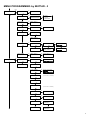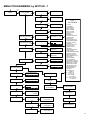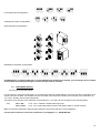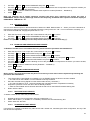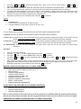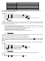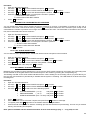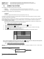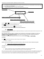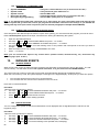
1
CONTROL UNITS R Series TECHNICIAN & USER MANUAL - Versione 4.0 - 2 1. INTRODUCTION The R serie control unit is composed of two elements: a board and a receiver, the latter contained in a small LCD keypad. To the basic configuration you can connect two radio receivers (positioned as needed in different places), which can handle 32 radio devices, for a total of 96 devices, addressable to 48 inputs. Inputs are freely assignable to 2 separate areas each of which fitted with 8 partial. The system is capable of receiving radio signals across the available bandwidth in 433MHz or 868MHz. Each device transmits simultaneously on different frequencies to avoid collisions radio. The method of radio transmission is fully digital FSK, and is of 128-bit rolling code type. The possibility to connect receivers or devices directly on the R485 bus makes the system very versatile, even for complex installations (houses and/or multi-storey structures, etc..). 1.1 FEATURES Fully compatible with all S series accessories 2 areas independent of each other, with the possibility of assigning devices to each area separately 8 programs per area that can be added to one another 1 automatic arming managed by a timer per area 4 user timers per area that can be assigned to different users for time-limited access 64 users that can be freely assigned 2 “route” type arming commands (Slave A-B) per area 48 freely programmable zones 6 programmable Open Collector outputs, 3 of which on board 3 radio modules that can be connected (contained in the keyboard K-Radio, or modules EXPR/S) 4 keypads that can be connected ( 3 model K-Radio keyboard with radio module integrated, or 4 model K-LCD normal keyboards ) 8 freely connectable and assignable plugs ( model PROXIMITY or PR ) Built-in telephone controller with 16 telephone numbers and optional voice synthesis module Recordable voice messages, 200 event (some pre-recorded) and 2 queue messages (identification system) Possibility of remotely managing the system from a PC via an optional RS-232 adapter or telephone line (optional remote management MODEM) Customizable data transmission with protocol CONTACT ID 1.2 CONNECTIONS +14.2 Vdc power supply Battery Faston Tamper line Fixed loads O.C. outputs Free exchange relay Internal Siren External Siren Telephones Telephone line I/O peripherals – Terminals +, -, ground, dedicated for the connection of the power supply – Faston terminals used for the connection of the backup battery – Dedicated terminals used for the connection of the anti-tamper line – Dedicated terminals used to supply power to sensor and other peripherals – Dedicated terminals used for the system's Open Collector outputs – Relay output that follows the behaviour of the siren outputs – Relay output used to connect piezo sirens (positive - supplying ) – Relay output used for the connection of external sirens (positive fail ) – Dedicated terminals used for the connection of phones – Dedicated terminals used to the connect the incoming telephone line – Terminals of BUS RS-485 used to connect the system peripherals (keypads, plugs. etc.) 3 PERIPHERALS TAMPER 4 TAMPER PERIPHERAL 1 TAMPER PERIPHERAL 2 TAMPER PERIPHERAL 3 TAMPER PERIPHERAL 4 KEYPAD 1 KEYPAD 2 KEYPAD 3 KEYPAD 4 TAMPER PERIPHERAL 17 TAMPER PERIPHERAL 18 TAMPER PERIPHERAL 19 TAMPER PERIPHERAL 20 TAMPER PERIPHERAL 21 TAMPER PERIPHERAL 22 TAMPER PERIPHERAL 23 TAMPER PERIPHERAL 24 PLUG 1 PLUG 2 PLUG 3 PLUG 4 PLUG 5 PLUG 6 PLUG 7 PLUG 8 TAMPER PERIPHERAL 25 EXPANDING OUTPUTS 1 TAMPER PERIPHERAL 33 EXPANDING INPUTS 1 TAMPER PERIPHERAL 65 TAMPER PERIPHERAL 66 TAMPER PERIPHERAL 67 RADIO EXPANSION 1 RADIO EXPANSION 2 RADIO EXPANSION 3 MENU PROGRAMMING by KEYPAD - 1 PERSONAL CODE MANAGE EVENTS (DEFAULT Technician 000000) Enter (✔) READ EVENTS (V) Down arrow (V) EVENTS OPTIONS ZONES MENU EVENTS LIST (✔) (✔) ZONES AREA (V) (✔) ZN:001 – ZONE NAME 111-------------------------- (V) ZONES FUNCTION (✔) ZN:001 – ZONE NAME 000-------------------------- (V) (✔) ZONES TYPE ZN:001 – ZONE NAME 000-------------------------- (V) (✔) ZONES STATUS ZN:001 – ZONE NAME (V) RADIO RECEIVER (✔) 1 AC LOSS 2 AC RETURN 3 LOW BATTERY 4 ZONE ALARM 5 ZONE TAMPER 6 USER ACCESS 7 TECHNICIAN ACCESS 8 ARMING 9 DISARMING 10 ZONE ACTIVATION 11 USER ENTRY 12 USER QUIT 13 TEL.CONNECTION 14 ZONE BREAKDOWN 15 PERIPHERICAL TAMPER 16 TAMPER 17 TELCO LINE FAULT 18 TELCO FAULT 19 DTMF ACCESS 20 DURESS 21 24H NO BURGLARY 22 FIRE ALARM 23 TAMPER BREAKDOWN 24 REMOTE ON / OFF 25 KEY ACTIVATION 26 EVENT MEMORY FULL 27 LIFE TEST 28 ON PROGRAM 29 OFF PROGRAM 30 AUTOMATIC ON / OFF 31 RADIO DEVICE TAMPER 32 RADIO DEV.LOW BAT. 33 RADIO DEV.OK BAT. 34 NO SUPERVISION 35 SUPERVISION OK 36 RADIO INTERFERENCE 37 NO GSM NETWORK (✔) NOTIFICATION LD 0 = immediate 1 = lagged 2 = counter 3 = smart 4 = 24 hours 5 = switch alarm ( fast inputs ) 6 = chime 7 = tecno 8 = system on/off 9 = duress ( with siren ) A = silent duress B = fire C= system only “on” D= system only “off” 0 = N.C. (normally closed) 1 = N.A. (normally opened) 2 = Filtered 3 = double balance 4 = disabled tamper zone ( valid only for tamper and tamper central terminal ) □ = Zone ready ● = Zone NOT ready (✔) LOCAL RECEIVER DEVICE ENABLED (✔) DEVICE NR.01 (V) (V) RESET RECEIVER REPEATER 02 … 03 (V) DEVICES (✔) DEV.01 – Ifxxx (✔) (V) SELF EXCLUSION (✔) ZN:001 – ZONE NAME IN. 01 à SYSTEM (V) (V) ARMING BY ZONES (✔) ZN:001 – ZONE NAME 000000000000000000 BATTERY LEVEL (V) ZONE à OUTPUT (✔) ZONE OO1 (V) From 1 to 8 for single program. 9 to all 8 program RSSI LEVEL (V) ZONES NAME (✔) (V) NAME: ZONE 001 Insert name DEVICE NAME Disp. 1/01 (V) ZONES DELAY (✔) DELAY: ZONE 001 0:00 (from 1 sec. to 15 min.) (V) AND GROUP (✔) ZN:001 – ZONE NAME 000000000000000000 (✔) TIME AND GROUP 01 0:00 Hash key # to return to the previous menu (V) AND GROUP TIMES (from 2 sec to 15 min.) 5 MENU PROGRAMMING by KEYPAD - 2 OUTPUTS MENU Enter (✔) (✔) OUTPUTS FUNCTION US:01 – OUT 01 000000000000000000 (V) Down arrow (V) OUTPUTS FUNCTION (✔) OU:01 – OUT 01 □ = N.C. output ● = N.A. output OU:01 – OUT 01 000000000000000000 0 = impul. Auto reset 1 = impul. No reset (V) OUTPUTS TYPE (✔) (V) OUTPUTS AREA (✔) OU:01 – OUT 01 000000000000000000 (V) OUTPUTS DELAY (✔) TIME: OUT 01 0:00 0 = system status 1 = no AC 2 = AC return 3 = low battery 4 = panic 5 = tecno 6 = no telephone line 7 = siren 8 = pre-alarm 9 = arming A = chime ( bell ) B = fire alarm C = fire reset D = pilot E = control led F = battery radio devices G = supervisions radio devices H = radio saturation I = no GSM network (from 1 min. to 240 hours) (V) OUTPUTS DURATION (✔) TIME: OUT 01 0:00 (from 5 sec. to 10 hours) 10 hours on display = 599:59 (V) LINKED INPUTS (✔) ZONE à OUTPUT 01 (V) S.STATUS/OUTPUTS (✔) OU:01 – OUT 01 000000000000000000 (V) OUTPUTS NAME TECHNICIAN MENU (V) (✔) TECHNICIAN CODE (V) RESET LOCK 6 (✔) NAME: OUT 01 Insert Name 0 = always active 1 = active when Progr.1 is armed 2 = active when Progr.2 is armed 3 = active when Progr.3 is armed 4 = active when Progr.4 is armed 5 = active when Progr.5 is armed 6 = active when Progr.6 is armed 7 = active when Progr.7 is armed 8 = active when Progr.8 is armed 9 = active when system is OFF A = active when system is ON MENU PROGRAMMING by KEYPAD - 3 USERS MENU Enter (✔) USERS AREA (✔) US:01 – USER 01 1-................ (V) Down arrow (V) USERS LEVEL (✔) 0 = master 1 = slave A 2 = slave B 3 = administrator US:01 – USER 01 000000000000000000 (V) USERS NAME (✔) NAME: USER 01 Insert name (V) USERS à OUTPUTS (✔) (✔) OUTPUT: USER 01 OUTPUT: USER 01 0 (V) USERS TIMER (✔) TIMER: USER 01 0 (V) (V) TIMER: USER 64 0 (✔) USERSàPROGRAMS (V) AREA 01 PROGRAMS (✔) (V) PROG.: USER 01 (V) AREA 08 PROGRAMS AREA PROGRAMS (✔) AREA 01 PROGRAMS (V) AREA 02 PROGRAMS (✔) (✔) (✔) CODE: USER 01 (✔) PROGRAM 01 PR:01 PROGRAM 1 (V) PR:01 PROGRAM 8 PROG.: USER 64 (✔) USERS CODES (✔) (✔) CODE: USER 01 111111 ZN:001 – Zone Name (V) PROGRAM 08 (V) (✔) SLAVE A ZONES ZN:001 – Zone Name (V) SLAVE A TIME ( from 1 min. to 12 hours ) (V) SLAVE B ZONES (V) SLAVE B TIME ( from 1 min. to 12 hous ) (V) (✔) PROG. à OUTPUTS PROG. 01 à OUTPUT 0 (V) (✔) PROG. à SIREN PROG. 01 à SIREN (V) (✔) PROGRAMS NAME (V) NAME PROG.01 PROGRAM 01 (V) SLAVE ARMING 0 NAME PROG.08 PROGRAM 08 7 MENU PROGRAMMING by KEYPAD - 4 DATE/TIME Enter (✔) Enter the day of the week from 0 to 6 (from Fri to Sat). Moving with the arrow right to enter dd / mm / yy h / min . Press Enter to confirm Down arrow (V) AREA TIMES (✔) (✔) AREA 01 TIMERS (V) (✔) SET TIMERS (✔) TIMER SUNDAY (V) (✔) TIMER SATURADY (✔) USER TIMER (V) (✔) USER TIMER 1 (✔) TIMER PROGRAMS (V) (✔) USER SUNDAY (V) (✔) USER SATURDAY (V) 01 (✔) EXCLUSION 01 FR 00 / 00 .>. 00 / 00 (V) (✔) 05 (✔) EXCLUSION 05 FR 00 / 00 .>. 00 / 00 SIREN DURATION SWITCH ALARM (V) (V) SIREN CYCLES SELF EXCL.CYCLES (V) QUICK ARM A:01 (V) (V) REMOTE SIREN QUICK ARM QUICK ARM A:02 (V) (V) (✔) CLOCK CORRECTION (V) SYSTEM TEST MODE (V) LOW BATTERY OFF (V) AC LOSS TIME (V) PULSE COUNTER (V) 8 03 > Sat 00 < 01 02 03 > Sat 00 < 01 02 03 > Sat 00 < 01 02 03 > < = Key 1 > = Key 2 Canc = Key 0 PR:01 PROGRAM 01 PR:08 PROGRAM 08 OTHER PARAMETERS 02 (V) USER TIMER 4 EXCLUSION 01 (V) AREA 02 TIMERS EXCLUSION Sun 00 < (✔) QUIT TIME QUIT TIME A:01 (V) (V) WELCOME MESSAGE QUIT TIME A:02 (V) TAMPER IN TYPE (V) AREA TAMPER (✔) TAMPER 12 MENU PROGRAMMING by KEYPAD - 5 PERIPHERALS Enter (✔) KEYPADS AREA (✔) 1234 1 (V) Down arrow (V) PLUGS AREA (✔) 12345678 11 (V) PLUGSàPROGRAMS (✔) PLUG 01 PROGRAMS (V) (✔) 12345678 (V) PLUG 08 PROGRAMS PROGRAMMING PLUG (✔) A:01 PROG.PLUG (V) NEW KEY CODE (V) (✔) NEW KEY CODE * - CONFIRM # - END A:02 PROG.PLUG (V) SYSTEM ID From 1 to 7 (V) KEYPADS SOUND (✔) 1234 (V) PLUGS SOUND (✔) 12345678 (V) REMOTE INPUTS (✔) 1 (V) REMOTE OUTPUTS (✔) 1 (V) ENABLE REPEATER (✔) 1 2 (V) NETWORK SPEED 9 MENU PROGRAMMING by KEYPAD - 6 MODEM Enter (✔) (✔) IDC PARAMETER IDC TELEPHONE 01 AC LOSS 301 Down arrow (V) (V) (V) RINGS NUMBER (V) IDC TELEPHONE 02 LOW BATTERY 3 309 (V) WAITING RESPONSE Max 60s. (V) IDC TELEPHONE 03 (V) ANSWER TIMEOUT Max 60s. (V) RADIO DEV.TAMPER 383 (V) IDC CODE (V) CALLBACK TEL. (V) RADIO DEV.LW.BAT. 384 (V) (V) IDC ENABLING RADIO NO SUPERV. 381 (V) (V) (V) TELEMNG TEL. IDC ATTEMPTS RADIO INTERF. (V) (V) (V) 344 LINE TEST GAP Max 240 ore LIFE TEST GAP 305 (V) LINE TEST HOUR (V) (V) LIFE TEST HOUR (V) CALLBACK ENABLED SYSTEM RESET TELCO LINE FAULT 351 (V) (V) ZONE RESTORING ON/OFF BY USER 401 (V) (V) FIRE ALARM GROUP ON/OFF 110 (V) 402 (V) DURESS 121 AUTOMATIC ON/OFF 403 (V) (V) REMOTE ON/OFF SILENT DURESS 407 122 (V) (V) ZONE BYPASS ZONE ALARM 570 130 (V) (V) WRONG CODE 461 ZONE TAMPER 137 (V) (V) PERIODIC TEST 602 PERIPHER.TAMPER 341 (V) (V) GSM PROBLEMS 352 24H NON-BURGLARY 150 (V) 10 (V) PROG.MODE ENTRY 627 MENU PROGRAMMING by KEYPAD - 7 Enter (✔) (✔) DIALER CALL OPTIONS (✔) MAX.ATTEMPTS MAX.ATTEMPTS 3 (V) Down arrow (V) (✔) REPEAT TIMES REPEAT TIMES 3 LIST OF EVENTS (V) (✔) CALL DELAY (V) CALL DELAY 15 15 (V) VOICE PRIORITY (✔) VOICE PRIORITY 0 (✔) EVENTàVOCAL BOX (✔) AC LOSS AC LOSS VOCAL BOX: 1 … 200 (V) (✔) EVENTàTELEPHONE (✔) AC LOSS 1234567890123456 (V) PHONE BOOK (✔) TELEPHONE Nr. 01 (✔) TELEPHONE Nr. 01 33932456XX (V) TELEPHONE Nr. 16 AREA TELEPHONES (✔) AREA 01 TELEPHONE (✔) (✔) TELEPHONE Nr. 16 33932145XX 1234567890123456 (V) AREA 02 TELEPHONE (✔) 1234567890123456 GSM MANAGEMENT MENU ACCESS TEL. (✔) 1234567890123456 GSM USE (V) CLEAR CACHE TEL. (✔) 1234567890123456 1 AC LOSS 2 AC RETURN 3 LOW BATTERY 4 ZONE ALARM 5 ZONE TAMPER 6 USER ACCESS 7 TECH.ACCESS 8 ARMING 9 DISARMING 10 ZONE ACTIVATION 11 USER ENTRY 12 USER QUIT 13 TEL.CONNECTION 14 ZONE BREAKDOWN 15 PERIPH.TAMPER 16 TAMPER 17 TELCO LINE FAULT 18 TELCO FAULT 19 DTMF ACCESS 20 DURESS 21 24H NO BURGLARY 22 FIRE ALARM 23 TAMPER BREAKDOWN 24 REMOTE ON/OFF 25 KEY ACTIVATION 26 EVNT MEMORY FULL 27 LIFE TEST 28 ON PROGRAM 29 OFF PROGRAM 30 AUTOMATIC ON/OFF 31 RADIO DEV.TAMPER 32 RADIO DEV.LW.BAT. 33 RADIO DEV.OK BAT. 34 NO SUPERVISION 35 SUPERVISION OK 36 RADIO INTERF. 37 NO GSM 38 – 85 ZONE 01 …ZONE 48 86 - 91 Output 01…. ...Output 06 92 - 99 A:1 Partial 1… ...A:1 Partial 8 100 – 108 A:2 Partial 1… ...A:2 Partial 8 SMS TEL. (V) CONFIRM NEED TEL. (✔) 1234567890123456 CREDIT MANAGEMENT CREDIT NUMBER (V) CALL RESET CODE (✔) CALL RESET CODE 123456 CREDIT TEXT (V) VOCAL MESSAGES (✔) SYSTEM MESSAGES (✔) *-REC ENTER-PLAY VOCAL BOX [ 1 ] CREDIT READING *-REC ENTER-PLAY VOCAL BOX [ 1 ] CREDIT REQUEST (V) AREA MESSAGES (✔) (V) EVENTS MESSAGES (✔) *-REC ENTER-PLAY VOCAL BOX [ 1 ] 11 MENU PROGRAMMING by KEYPAD - 8 PERSONAL CODE USER CODE (DEFAULT user 01= 111111) Down arrow (V) Enter (✔) Use the numeric keys to configure the programs to be included (from 1 to 8) □ = Configured ● = Not Configured ARMING (V) (✔) Use the Up and Down arrow keys to scroll through the list of events. Press enter to exit. READ EVENTS (V) (✔) NAME: USER 01 Use the buttons to change the USERNAME (V) (✔) CODE: USER 01 Use the numeric keys to change the USER CODE (V) (✔) DATE / TIME Enter the day of the week from 0 to 6 (from Sun to Sat) Moving with the arrow right to enter dd/mm/yy h/min. Press ENTER to confirm. (V) (✔) PROGRAM KEY PROGRAM KEY * - CONFIRM # - END (V) (✔) EXECUTE CALLBACK EXECUTE CALLBACK * - CONFIRM # - END (V) (✔) 0 = Disabled 1 = Enabled (✔) CREDIT INFO TELEMNG ON Set To 1 for PC Connection (V) GSM MANAGEMENT (V) FIRE RESET 12 (V) ASK FOR CREDIT Press button “X” to visualize on LCD Display, SoftWare level and GSM level MENU VOICE GUIDE After the response from the dialer, press the pound key to enter the voice menu. Insert Personal Code Correct Code Wrong Personal Code If user enabled to more areas, press * asterisk for changing area Insert 1 to check the status of the system User not authorised. /// Area X: System Armed, Program: Y,K... Area X: System Disarmed. Insert 2 to act on the system. User not authorised. /// Insert 1 to activate Program 1 Insert 2 to activate Program 2 Insert ... Insert 9 to activate all Programs Insert 0 to deactivate the system Insert # to quit Insert 3 to use the remote controls. Select output (2 figures) Insert # to quit Insert 4 to check the status of the zones. User not authorised. /// System ready ( for all input at rest ) Input Door activated Kitchen Window activated Kitchen Window activated Insert # to quit Insert 5 to check the status of the outputs. User not authorised. /// Output X activated. Output Y deactivated. Output... Insert 6 to suspend the call queue. Attention! Some Zones are not Ready! Insert 1 to exclude the Zones 2 to exclude them all 3 to ignore Insert # to quit Bathroom Window: Insert 1 to deactivate 2 to ignore … Kitchen Window: Insert 1 to deactivate 2 to ignore User not authorised. /// Insert 1 to activate Garden Light Insert 2 to deactivate Garden Light Garden Light activated / deactivated Bathroom Window deactivated Call Queue suspended. The voice " unauthorized user " is used when the code you use to enter the menu on the voice guidance is not a valid code for that area.. 13 FEATURES AND CONNECTIONS Note: it is always advisable to connect the peripherals in cascade, in order to enter and exit each peripheral. The connection cable must be shielded and possibly “twisted” to be able to benefit from maximum efficiency and length. CONNECT THE BATTERY TO THE FASTON CONNECTORS OF THE SYSTEM (LOAD STATUS CONTROL ACTIVE). YOU CAN ALSO CONNECT AN ADDITIONAL BATTERY TO THE FASTON CONNECTORS OF THE POWER SUPPLY (LOAD STATUS CONTROL UNAVAILABLE). 1.3 KEYPADS AND PLUGS The control peripherals that can be used with this system include: Keypads (model K-LCD or K-RADIO ), up to a maximum number of 4; Plugs (model PROXIMITY or PR/S), up to a maximum number of 8 All these peripherals must be connected to terminals A, B, +12V and –. Before powering the system, you need to differentiate the peripherals, which means assigning the keypads using their dipswitches and the plugs using their jumpers. For information on addressing, see the following figure: ATTENTION: always follow an incremental order starting from 1 both for the keypads and plugs, without forgetting any of the locations. 14 K-LCD Dip Switch Configuration K-RADIO Dip Switch Configuration PR/S Dip Switch Configuration PROXIMITY Dip Switch Configuration PLEASE NOTE: as already explained in section AREAS, after powering the system, you will always have to enable each peripheral manually following the instructions provided in sections: 1.4 EXPANDING INPUTS The unit has 48 via radio inputs. For any need you can get 8 wired inputs, by connecting the optional module EXPIN / S; these inputs are configurable in the system from IN41 to IN48. This module must be connected to the serial line RS-485, which belongs to the terminals A, B, +12 V and - already used for other peripherals. The inputs, which are part of the expansion to terminals IN1, 2, 3 to IN8, can be configured in the following kinds: from IN1 to IN6 IN7 and IN8 = N.C. / N.O. / Filtered / Double balancing inputs = N.C. / N.O. inputs alternatively used for fast Switch-Alarm or inertia contacts Make sure that the expansion's switches (DIP-SWITCH) are properly placed to off (see diagram). For the input connection, follow the instructions in paragraph 1.10 – ZONE INPUTS. 15 Dip Switch Configuration 1.5 EXPANDING OUTPUTS To expand the system by adding further outputs (the maximum configuration is 6 outputs), you need to connect optional module EXPUS/S to serial line RS485. You can use up to a maximum of 1 EXPUS/S module; Make sure that the expansion's switches (DIP-SWITCH) are properly placed to off (see diagram). Dip Switch Configuration The expansion adds three new outputs (terminals OUT1, OUT2 and OUT3) that can be used in the same way as the three on system board. 1.6 RADIO EXPANSION The control unit in the initial configuration (base + keyboard) can store up to 32 devices including remote controls, magnetic contacts, volumetric detectors and curtain effect detectors. In order to expand the number of radio devices you have to connect other keyboards K-Radio, or expansions EXPR / S on the RS485 serial line; the maximum number of expansions is 2, and allows you to bring the devices to 96 presets. 1.6.1 - RADIO EXPANSION K-RADIO Each keypad must be configured using its DIP switches on the rear; KEYBOARD ADDRESS only for keypad configuration HW ADDRESS only for expansion configuration The first keypad must always have the dip KEYBOARD ADDRESS and HW ADDRESS in OFF position. Additional keyboards must have the dip, both KEYBOARD ADDRESS and HW ADDRESS setted up considering the number of keyboards and / or radio receivers present, and setting up again following an ascending order, starting from the No. 1 forward, never forgetting any position. As in the following figure: WARNING: The keyboards follow their configuration (on K-Radio, Keyboard Address), with their ascending order. The radio expansions follow their configuration (on K-Radio HW Address), which must be made taking into consideration the possible Expr / S present and must always go in ascending order starting from the No. 1 forward, without neglecting any position. The 1st radio expansion in each case is that present on the 1st K-RADIO 1.6.2 RADIO EXPANSION EXPR/S Each board EXPR / S, which can store up to 32 devices, must be configured through its switches on the rear à HW ADR, following the pattern shown in the following figure " Dip Switch Configuration ". 16 WARNING: the " sequence " of the number of configuration must take into account any expansion present on K-Radio and should be continued accordingly. Example: if two expansions already present on K-Radio, The Dip configuration of the EXPR must be the No. 3. Function DIP 1,2,3,4 Dip Switch Configuration 1.7 VOICE MODULE The system is fitted with a built-in telephone controller that can be used with an optional voice sampling module (model SV/S) to provide voice synthesis features to the telephone controller. For information on how to program and use this module, see section VOICE SYNTHESIS. To connect the telephone line, use terminals LA and LB on the module. The other telephone devices present on the telephone line must be connected between terminals TA and TB, to ensure that the alarm system has priority over any other telephone device connected to the line. IMPORTANT: before inserting or removing the voice module, disconnect the system from the power supply (battery or mains) and wait at least 10 seconds. 1.8 AREAS OPERATION LOGIC The unit manages two areas with the possibility of activating multiple areas simultaneously. Each zone can be assigned to different areas; in this case the breach of that zone will cause an alarm only if ALL of the areas which it is assigned are included. 1.9 ALLOCATION OF AREAS TO THE ZONES Each area corresponds to an autonomous system, with its users, its keyboard, its plug and its inputs. All these resources are freely assignable, by programming. If you use multiple areas, each area is completely independent of other areas. NB: All resources ( keyboards, users, plugs etc. ) that are not associated with any area, (value 0) are disabled and therefore not working. 1.10 ZONE INPUTS “ Normally closed ” mode These refer to the COM terminal that corresponds to the power supply negative. By default, they are NORMALLY CLOSED (N.C.) input designed to be connected as follows: You can also configure a normally closed input as switch-alarm (see section Inputs function). TAMPER B/S MASCH - + N.C. Normally Closed Contact From Z1 to Z8 COM or Negative 17 “ Double balancing ” mode Normally Closed Tamper Contact Normally Closed Contact TAMPER B/S From Z1 to Z6 MASCH - + N.C. COM or Negative You can freely protect each input from the cutting or short-circuit of cables (protection against tampering, 24h TAMPER). To do so, you need to program a “double balancing” input and connect the resistors supplied as shown in the following diagram: PLEASE NOTE: for this connection to be effective, you will need to connect the resistors directly to the sensor and not to the system. Note: 1K = 2,2K = 1.11 EXTERNAL SIREN Brown-Black-Red Red-Red-Red The system is designed to directly control self-powered sirens with a positive lock (+12 V). The output used for this purpose is terminal +C (positive - receiving). Terminals + and – are instead used to provide the recharge current for the siren battery (13.8 V output). 1.12 FREE EXCHANGE ALARM RELAY You can use the free exchange of the alarm relay. The maximum current that can be handled by this contact is 2A. It can be used for sirens with N.C. contact lock and luminous and/or acoustic alarms other than those issued by the siren. 1.13 INTERNAL SIREN Connect a siren directly between terminal +PZ and a negative pole of the power supply (-). ATTENTION: use ONLY indoor piezo sirens (for example model AMC PZ2). 1.14 PROGRAMMABLE OUTPUTS The system has 3 freely configurable Open Collector outputs ( that can be expanded to 6 ). These outputs are connected to the OUTPUTS terminals on the board. When an output enables/disables (depending on the set polarity), it transmits a reference signal to the negative pole. In the opposite case, it does not generate voltage, but remains open (high impedance status). The maximum current that may circulate on each output is 100 mA. If the load is expected to be above the maximum permitted value, it is necessary to use a relay. ATTENTION: ALWAYS connect a diode, as shown in the figure, when using relays. Control Unit “ +12Vdc ” Diode 18 Relay Coil Control Unit “ Outputs ” 2. PROGRAMMING NOTE: before programming any parameter, it is important to know how the keypad keys work, be familiar with the terms used in this manual and know the sequence that has to be followed. 2.1 2.1.1 KEYPAD KEYS AND LUMINOUS INDICATORS K-LCD or K-RADIO keypad In addition to the keys numbered from 0 to 9, the keypad also has other keys with symbols that are assigned to the specific features, depending on the menu selected during the programming phase. Note: to assign a letter instead of a number to a features, you need to press in sequence two numerical keys: Insert Code Quick Arm ( if enabled ) Command Pilot Outputs Control Pilot Output Status Remove Digit Code Confirmation Code A = press 0 twice B = press 1 twice C = press 2 twice D = press 3 twice E = press 4 twice The keypad also has 3 LEDs that are used as luminous indicators. Yellow LED : provides information on the status of the system (On = system armed, Off = system disarmed) Red LED : provides information on stored events (On = Event in memory to read, Off = No event to read) Green LED : provides information on control status of the system (On = System in good working order, Off = Open or faulty zones or peripherals) Note: all details on the key features are provided in the following sections and described in detail in the paragraphs related to the individual programming phases. 19 2.1.2 K-RADIO keypad The K-Radio keypad, in addition to the functions and indications of the LEDs described above, has in the back of the card other LEDs and DIP switches used to manage the on-board radio expansion. Green Led Red Led Multicolour Led For the setting of the micro switch, HW ADDRESS and KEYBOARD ADDRESS, see the specific paragraph “1.3 KEYPADS AND PLUGS ” and “1.6.1 RADIO EXPANSIONS ”. FUNCTIONS OF THE DIP-SWITCH, as well as in the specific paragraphs is given below Dip 1 = when ON is being storing / canceling of wireless devices Dip 2 = indicates the type of signal that is necessary to send from your device at the phase of self learning, when OFF only signals LEARN (press the little key on the eponymous device), when ON all signals are valid (Learn, alarm, tamper and supervision) Dip 3 à only on EXPR / S (on the K-RADIO disabled) = enables the Tamper device micro switch Dip 4 = disable the SATURATION RADIO detection system GREEN LED (RADIO SECTION STATUS) OFF ON SLOW FLASHING FAST FLASHING FLASH EVERY 2 SECONDS Indicates that the expansion is fails or not power supplied. Indicates communication problems with the system (for EXPR / S it’s possible that A and B are connected wrong) / RED LED (RADIO DEVICES STATUS) Normal Operation (Flashing) Indicates the learning of a new device At least one radio device open Communicating but not enabled in central Storage device completed Normal operation (in use) At least one non-supervisory SIGNIFICANCE OF MULTICOLOR LED (inside K-RADIO) Multicolor LED indicates the correct reception of radio signals transmitted from devices programmed. At each reception will turn on for one second, then the color indicates the intensity of the signal received in accordance with the following correspondence: Green – Better Signal Yellow – Sufficient Signal Red – Poor Signal 20 2.2 USING THE MENU To open the system menus, you always need to enter a user code. The system offers 2 different menus: the TECHNICAL MENU that can be used to program all the system parameters and the USERS MENU that can be used to perform operations reserved to users like arming, programming keys, etc.). 2.3 ACCESSING THE TECHNICAL MENU To open the Technical Menu, which enables you o change all the system parameters, you need to enter a technician code and press to confirm. The default technician code is 00000. Procedure: - Enter the TECHNICIAN code (the default code is 000000) and press to confirm. 2.4 ACCESSING THE USERS MENU First of all check that the keypad is configured to be used in one of the areas enabled for access. Then, press to display the area you wish to use. Enter the user code and press to confirm. The default setting of this parameter is 111111. Procedure: - Enter the USER code (the default code is 111111) and press to confirm. ATTENTION: User 1 is the only user assigned to Area 1 and to the default user code shown above. For information on how to assign areas and set the user code for other users, see the relevant paragraphs. 2.5 BROWSING THE MENUS Return to the previous menu Select the next item Select previous item Confirmation item Note: menus scroll in a loop; therefore when you reach the last parameter, you can press first one). to return to the 21 2.6 SETTING DATA WITHIN A MENU You can use 3 different graphic interfaces depending on the parameters you wish to change: Insert Value ( double pressure for letter ) Move the cursor to the left ( 1 digit ) Move the cursor to the right ( 1 digit ) Move the cursor to the right ( 8 digits ) Move the cursor to the left ( 8 digits ) Confirm and Exit First Move the cursor to the left ( 1 digit ) Move the cursor to the right ( 1 digit ) Move the cursor to the right ( 8 digits ) Move the cursor to the left ( 8 digit ) Item edit Confirm and exit Second Quick Selection Insert Value Remove Value Confirm Value Third 22 2.7 INITIAL RESET Verify that the system is not powered. Supply power (through the battery or mains) by pressing the RESET key on the board for at least 2 seconds. When you release the key, the system deletes all the data and resets all parameters to their default values. Summary of the default settings: - KEYPAD 1 enabled - Codes: TECHNICIAN (000000); USER 1 (111111) - Inputs configured as N.C., and the first 8 assigned to Area 1 - Inputs configured as INSTANTANEOUS - NO electronic key enabled - NO INPUT and/or OUTPUT EXPANSION MODULE enabled - System TAMPER disabled - TEST MODE enabled (ATTENTION! IN THIS MODE THE SIREN IS DISABLED) - REMOTE MANAGEMENT (via cable and remotely) disabled 3. PERIPHERALS 3.1 CONFIGURING THE KEYPADS ( Keypads area ) After the initial reset, the only operating keypad is KEYPAD 1, where all the dip-switches are in position OFF. You can use this keypad to enable other keypads and assign them to an area. PLEASE NOTE: before powering the system, verify that each keypad is configured with a unique address, following the instructions provided in section – KEYPADS AND PLUGS. Procedure: Enter the technician code to open the Technical Menu and press to confirm. Uses keys and to select PERIPHERALS and press to confirm. Select KEYPADS AREA and press to confirm. Use keys and # to move the blinking cursor to the position that corresponds to the keypad you wish to enable (keypad from 1 to 4), shown in the row above. Enter 1 or 2 to assign a keypad to the desired area or remove the assignment. To view all the areas to which a keyboard is assigned press 0 repeatedly. In particular: = Keypad Disabled = Keypad Enabled at least one area 1 = Keyapd associated with the area 1 2 = Keyapd associated with the area 2 After assigning all the required keypads, press to confirm. Note: pay attention not to enable keypads that don't exist, otherwise the system will issue a PERIPHERAL tamper warning. Warnings related to the tampering of keypads display as PERIPHERAL TAMPER 1….4. After each enabling operation, check immediately that the corresponding keypad is able to correctly communicate with the system: all keypads assigned to the same area of the keypad used for programming should display SYSTEM LOCK, while those assigned to a different area will alternatively display the DATE/TIME and WELCOME MESSAGE. Even the keypads of area 1 will alternatively display the DATE/TIME and WELCOME MESSAGE, though only when you exit a menu. 3.2 CONFIGURING THE PLUGS After the initial reset, NO plug (though connected) is enabled (which means that that the control LED is off). You can use an enabled keypad to enable other connected plugs (models PR/S and PROXIMITY). After having enabled them, you need to specify which plug users can use to program their own keys (it is possible to specify one plug per area only). ATTENTION: if the keys are already used for other systems, you will need to change the SYSTEM ID. PLEASE NOTE: before powering the system, verify that each plug is configured with a unique address, following the instructions provided in section 1.3 – KEYPADS AND PLUGS. 23 Procedure: Enter the technician code to open the Technical Menu and press to confirm. Use keys and to select PERIPHERALS and press to confirm. Use keys and to select PLUGS AREA and press to confirm. Use keys and # to move the blinking cursor to the position that corresponds to the plug you wish to enable (plugs from 1 to 8), shown in the row above. Enter 1 or 2 to enable/disable the plug for the desired area. In particular: 0 1 2 = Plug disabled = Plug assigned to area 1 = Plug assigned to area 2 After assigning all the required plugs, press to confirm. NOTE: after enabling the plugs, check that the green system control LED switches on when all the zones of the area are idle. ATTENTION: pay attention not to enable plugs that don't exist, otherwise the system will issue a PERIPHERAL tamper warning. Warnings related to the tampering of plugs display as PERIPHERAL TAMPER 17…24. 3.3 PLUGS à PROGRAMS From this menu you can define, for each plug, which partial programs you can arm / disarm Enter the technician code to open the Technical Menu and press to confirm. Use keys and to select PERIPHERALS and press to confirm. Use keys and to select PLUGS à PROGRAMS and press to confirm. Use keys and to select the desired plug ( from 01 to 08 ) and press to confirm. Use CANC key to select the program that can be armed / disarmed by this plug ( max 3 ). Press to confirm. 3.4 SELECTING THE PLUG TO PROGRAM KEYS You can make that one of the plugs enabled can be used for programming the electronic keys (model Beatle or INS / EP). To do this follow the steps below: Enter the technician code to open the Technical Menu and press to confirm. Use keys and to select PERIPHERALS and press to confirm. Use keys and to select PROGRAMMING PLUG and press to confirm. Use keys and to select the desired Area and press . Press any key from 1 to 8 to select the desired plug. Press to confirm. Note: if there are several areas, repeat the procedure described for all the remaining areas. PLEASE NOTE: always verify that the plugs set for the programming of keys belong to the selected area, otherwise you will no longer be able to perform any operation with it. At this point you can check that the plugs are working correctly by following this procedure: 24 Press # to exit from the Technician Menu until the WELCOME MESSAGE displays. Enter your user code to open the Users Menu and press to confirm. Use keys and to select PROG. KEY and press to confirm. Press . The LEDs on the programming plug will start to flash at short intervals. Insert a key and leave it inserted until the LED switches off. Remove the key and quit the Users Menu by pressing # several times. Insert the key in each plug and verify that the LEDs switch on as shown below. 3.5 OPERATION OF THE PLUGS LEDS With key removed: 1 2 3 4 Orange LED on Yellow LED on Red LED on Green LED on Not used System armed Alarm memory All zones are idle Orange LED on Yellow LED on Red LED on Green LED on Not used Used to notify the arming of a program Used to notify the arming of a program Used to notify the arming of a program With key inserted: 1 2 3 4 - During the quit time Yellow LED flashes. During an alarm condition, the LEDs switch on and flash simultaneously. During a disarming the Orange LED will turn on with the armed program LED. 3.6 DELETING ALL THE PROGRAMMED KEYS ( new key code ) Every key is always assigned to a user. When you change a user code, the corresponding keys continue to be valid and are not automatically deleted. To delete a key (for example because it has been lost), you need to delete all the key using parameter NEW KEY CODE. This operation changes the key code only, not the user code. NOTE: after deleting the keys, it is necessary to reprogram them all. To do so, follow this procedure: Enter the technician code to open the Technical Menu and press to confirm. Use keys and to select PERIPHERALS and press to confirm. Use keys and to select NEW KEY CODE and press to confirm. Press to confirm the deletion of all the keys, then press # to quit. New key code = Confirm # = End 3.7 Keypad display IDENTIFYING THE SYSTEM If you are planning to use a key for several systems of the same type, you need to change the system ID, using function SYSTEM ID, in order to change the memory location there the selected system code is stored on the key. To perform this operation, follow this procedure: Enter the technician code to open the Technical Menu and press to confirm. Use keys and to select PERIPHERALS and press to confirm. Use keys and to select SYSTEM ID and press to confirm. Press DEL followed by a numerical key from 0 to 7 to indicate the system ID number. Press to confirm. Please note: if the programmed keys are used for AMC systems other than series S or C, you will not need to change parameter SYSTEM ID. Please remember that “Beatle” keys can be used to manage a maximum of 2 systems (that is two different SYSTEM IDs). 25 3.8 ENABLING THE BUZZER ON KEYPADS AND PLUGS Every keypad and plug has a BUZZER that provides an acoustic warning for the quit time, the entry time and other features. To enable or disable the buzzer, follow this procedure: Enter the technician code to open the Technical Menu and press to confirm. Use keys and to select PERIPHERALS and press to confirm. Use keys and to select KEYPADS SOUND or PLUGS SOUND and press to confirm. Use keys and # to move the blinking cursor to the position that corresponds to the desired keypad or plug. Press DEL to enable or disable the sound of the keypad or plug: = Sound enabled = Sound disabled Press to confirm 3.9 ENABLING INPUT EXPANSION MODULES Before performing any programming operation, you need to set the address of the expansion modules using the DIP – SWITCHES, as described in paragraph 1.4 – EXPANDING INPUTS. To enable one or more input expansion modules, perform the following procedure: Enter the technician code to open the Technical Menu and press to confirm. Use keys and to select PERIPHERALS and press to confirm. Use keys and to select REMOTE INPUTS and press to confirm. Press DEL to enable or disable the expansion module (Enabled= Disabled=) Press to confirm. Note: pay attention not to enable expansion modules that don't exist, otherwise the system will issue a PERIPHERAL tamper warning. Warnings related to the tampering of expansion modules display as PERIPHERAL TAMPER 33. 3.10 ENABLING AN OUTPUT EXPANSION MODULE Before performing any programming operation, you need to set the address of the expansion modules using the DIP – SWITCHES, as described in paragraph 1.5 – EXPANDING OUTPUTS. To enable one or more output expansion modules, perform the following procedure: Enter the technician code to open the Technical Menu and press to confirm. Use keys and to select PERIPHERALS and press to confirm. Use keys and to select REMOTE OUTPUTS and press to confirm. Press DEL to enable or disable the output expansion module (Enabled= Disabled=) Press to confirm. Note: pay attention not to enable expansion modules that don't exist, otherwise the system will issue a PERIPHERAL tamper warning. Warnings related to the tampering of output expansion modules display as PERIPHERAL TAMPER 25. 3.11 ENABLING AN EXPR/S RADIO EXPANSION MODULE Before proceeding to the device’s set up it’s necessary to assign it an address trough the relative HWADR DIPs, as described in paragraph 1.6 – EXPR/S RADIO EXPANSION. To enable one or more EXPR/S Radio Expansions please follow the procedure below: 26 Enter the technician code to open the Technical Menu and press to confirm. Use keys and to select PERIPHERALS and press to confirm. Use keys and to select EXPRS EXPANSIONS and press to confirm. Use keys and to select ENABLING and press to confirm. Use keys and # to move the blinking cursor to the position that corresponds to the expansion module you wish to enable, shown in the row above. Press DEL to enable or disable the EXPR/S radio expansion module (Enabled= Disabled=) Press to confirm. Note: pay attention not to enable expansion modules that don't exist, otherwise the system will issue a PERIPHERAL tamper warning. Warnings related to the tampering of EXPR/S radio expansion modules display as PERIPHERAL TAMPER 65…67. 3.12 NETWORK SPEED You can set a different speed on the transmission of data on the BUS. Default Value " 0 ". When you notice a slowdown in response time during programming by keyboards (caused by wiring of the bus " old " or not connected in cascade), you can increase the data rate, bringing the parameter to 1 or 2 . Enter the technician code to open the Technical Menu and press to confirm. Use keys and to select PERIPHERALS and press to confirm. Use keys and to select NETWORK SPEED and press to confirm. Insert 1 or 2 (CANCEL button (X) to erase the previous value). Confirm with enter key (). 3.13 ENABLING AND DISABLING RADIO DEVICES To Enable or Disable one or more Radio Devices, please follow the procedure described below: Enter the technician code to open the Technical Menu and press to confirm. Use keys and to select INPUT and press to confirm. Use keys and to select RADIO RECEIVER and press to confirm. Use keys and to select the desired RECEIVER ( LOCAL, 02, 03 ) and press to confirm. Use keys and to select DEVICE ENABLE and press to confirm. Use keys and # to move the blinking cursor to the position that corresponds to the device you wish to enable, shown in the row above. Press DEL to enable or disable the device (Enabled= Disabled=) Press to confirm. 3.13.1 LEARNING A NEW RADIO DEVICE Before using a new radio device with the panel it’s necessary to let it learn from an expansion by following the procedure described below: Turn ON the DIP1 FUNCTIONS on K-RADIO or on the EXPR/S where the device has been enabled The red LED on the K-Radio or on the EXPR/S must stay turned off Send the selected Learnig Signal from the desired radio device ( see below ) The red LED will turn on for 1 second indicating the operation has been completed successfully Repeat the operation to learn the other devices already enabled After the last enabled device has been learned the red LED on the EXPR/S will start blinking fast Return OFF the DIP1. 3.13.2 DELETING RADIO DEVICES To delete a radio device, follow the procedure below: Disable the device from its expansion referring to paragraph 3.11 Switch ON the DIP1 ( on K-Radio or on EXPR/S ) until the red LED starts blinking fast Switch back OFF the DIP1 3.13.3 CHANGING A RADIO DEVICE If necessary it’s possible to substitute any radio device with a similar one, mantaining the same configuration, but only if the two devices are equivalent. 27 To substitute a radio device, follow the procedure below: Disable the device from its expansion (refer to paragraph 3.11) Turn ON the DIP1 ( on K-Radio or on EXPR/S ) until the red LED will start blinking fast Turn back OFF the DIP1 Enable again the device on its expansion (always referring to paragraph 3.11) Turn ON the DIP1 of the expansion where the device has been enabled The red LED must remain turned OFF. Send the selected Learnig Signal from the desired radio device The red LED will turn ON for 1 second indicating that has been correctly learnt Switch back OFF the DIP1 3.14 MEANING OF SIGNALLING LED OF THE SECTION RADIO ( INSIDE THE K-RADIO or EXPR/S ) GREEN LED ( RADIO SECTION STATUS ) RED LED ( DEVICE STATUS ) OFF The expansion is out of Order or not Supplied Normal functioning ON Communication problems ( A and B terminals connection wrong ) ( Flash ) New device learnt / SLOW BLINKING FAST BLINKING FLASHING At least a device cover is open Communicating but not yet enabled Device’s storing completed Normal functioning ( in use ) At least one supervision missed 3.15 MEANING OF THE MULTICOLOR LED ( OUTSIDE THE EXPR/S or INSIDE THE K-RADIO ) The external multicolor LED shown the correct reception of the device’s radio signals. During each reception it will turn on for 1 second, the color will indicate the signal strength referring the following values: Green – Signal Excellent Yellow – Signal Sufficient Red – Signal Poor 3.16 LINKING THE RADIO INPUTS TO THE WIRED INPUTS To let the panel correctly manage the radio zones you first must link them to the wired zones. Once done, will be possible to assign them the Area and configure the other parameters of the zone, like a normal wired zone, trough the ZONES MENU. Procedure: Enter the technician code to open the Technical Menu and press to confirm. Use keys and to select MENU INPUT and press to confirm. Use keys and to select RADIO RECEIVER and press to confirm. Use keys and to select the desired RECEIVER ( LOCAL, 02, 03 ) and press to confirm. Use keys and to select DEVICES and press to confirm. Use keys and to select the device you wish to configure and press to confirm Use keys and to select the input of the device you wish to assign (es. IN.01 à Panel) and press to confirm. Use the numerical pad to define the wired zone you wish to associate to the selected radio input ( from 1 to 48 ). Press to confirm. 3.17 RSSI LEVEL ( RECEIVED RADIO SIGNAL STRENGTH ) and BATTERY LEVEL It’s possible to directly view the radio device’s received signal level from the K-LCD display. This feature allows to periodically monitor the correct radio link between the device and its receiver. Legend: 28 . - Excellent Signal … - Poor Signal It’s possible to directly view the radio device’s battery charge level from the K-LCD display. This feature allows to periodically monitor the battery charge level of the any radio device. . ………… Legend: - Battery Level Ok - Battery Level Low Procedure: Enter the technician code to open the Technical Menu and press to confirm. Use keys and to select MENU INPUT and press to confirm. Use keys and to select RADIO RECEIVER and press to confirm. Use keys and to select the desired RECEIVER ( LOCAL, 02, 03 ) and press to confirm. Use keys and to select DEVICES and press to confirm. Use keys and to select the device you wish to control and press to confirm. Use keys and to select the desired parameter à BATTERY LEVEL or à RSSI LEVEL and press confirm. Press Enter and then # to exit. to 3.18 DEVICE NAME For each device it’s possible to modify its name. The maximum length allowed is 16 digits. Procedure: Enter the technician code to open the Technical Menu and press to confirm. Use keys and to select MENU INPUT and press to confirm. Use keys and to select the desired RECEIVER ( LOCAL, 02, 03 ) and press to confirm. Use keys and to select DEVICES and press to confirm. Use keys and to select the device you wish to configure and press to confirm Use keys and to select DEVICE NAME and press to confirm In the upper row will appear the number and the name of the device, in the lower row will be shown the default name and the cursor will blink in the first position. Use the alphanumerical keypad to change the character and keys and to move the blinking cursor to the left or right. Press DEL to delete a character or enter a blank space between two characters. Press to confirm. 4. SETTING THE ZONES After the initial reset, the settings of each zone will be the following: - AREA =0 (only the zones from 1 to 8 are enabled in Area 1) - FUNCTION =0 (zone configured with an immediate function) - TYPE =0 (zone configured as normally closed) To configure one or more zones differently, refer to the instructions provided in the following sections. 4.1 ENABLING ZONES ( Zones Area ) To enable or disable one or more zones, follow this procedure: Enter the user code to open the Technical Menu and press to confirm. Use keys and to select ZONES MENU and press to confirm. Select ZONES AREA and press to confirm. Use keys and to move the blinking cursor by one position at a time or keys and to move it by 8 positions at a time and select the zone you wish to enable or disable. Enter 1 or 2 to assign the selected zone to one or more areas. To display all the areas to which a specific zone is assigned, press 0 several times. After enabling all the zones necessary, press the Enter key to confirm. For information on the enabling and assignment of zones, refer to the following: . = Zone disabled - = Zone enabled and assigned to at least one area 1 = Zone enabled and assigned to Area 1 29 2 = Zone enabled and assigned to Area 2 Note: - DO NOT enable zones that you are not planning to use. - The enabling of wired inputs from 41 to 48 is always dependant on the enabling of the input expansion module, as explained in the introductory section of this chapter. 4.2 PROGRAMMING THE ZONES FUNCTION To set the function of one or more zones, follow this procedure: Enter the technician code to open the Technical Menu and press to confirm. Use keys and to select ZONES MENU and press to confirm. Use keys and to select ZONES FUNCTION and press to confirm. Use keys and to move the blinking cursor by one position at a time or keys and to move it by 8 positions at a time and select the zone you wish to change. Enter a number from 1 to 9 or a letter between A and B to set the desired function (see description below ). Note: For the letter A, type 2 times 0, for the letter B, type twice any other number. The section that follows lists all the functions along with the corresponding description: 0 = Immediate: alarm function with no delay. 1 = Lagged: alarm function with lagged response time, programmable from 1 second to 15 minutes. 2 = Counter: enables the alarm after the number of violations specified in parameter PULSE COUNTER in the OTHER PARAMETERS Menu. The counter is reset 1 minute after the last violation. 3 = Smart: “immediate” function, which becomes automatically lagged when a lagged input enables. You can use this function to define a “route” from a (lagged) zone to the peripheral in order to be able to exclude the system (using a keypad or plug). 4 = 24 hours: enables the alarm 24 hours a day, regardless of the system status (armed/excluded). 5 = Switch Alarm (fast inputs): normally closed alarms with a very high pulse count. They are used to protect shutters or vibrating systems. The system can assign this function only to the last 2 inputs of the input expansion ( 47-48 ). When an input is configured with this function, the system automatically configures it as N.C. The sensitivity of the sensor can be adjusted with parameter PULSE COUNTER in the OTHER PARAMETERS Menu. 6 = Chime: when the system is off, it produces a 10 second acoustic sound for the keypad or for the enabling of a programmed output. When the system is armed, the function enables immediately, producing an alarm if violated. You can disable the sound of the keypad or output with the following shortcut command: #331#=Disable, #231#Re-enable. 7 = Tecno: this input is used for technological type of alarms. Together with the telephone controller, it can be used as silent alarm or to signal technical events by phone (VOCAL OR DIGITAL). You can also assign a programmable output and use it to automatically operate other equipment. This is a 24 hour input and is therefore always active, regardless of the status of the system. 8 = System ON/OFF: it enables to manage any program set by means of a pulsed command. The operating logic depends on the input configuration (N.C. or N.O.). It is not possible to use this function with stable commands. To assign the number of the program to arm (PROGRAM 1..8), see Menu QUICK ARM BY INPUTS, 9 = Duress (with siren): it is used to enable a panic alarm with siren. The operating logic depends on its configuration (N.C. or N.O.). It is a 24 hour input and is therefore always active regardless of the system status (armed/excluded). It can be used to enable a call to the controller, enable a assigned output or even to send digital alarms (ID CONTACT). A = Silent Duress: B = Fire: it is used to enable a silent panic alarm (without siren) The operating logic depends on its configuration (N.C. or N.O.). It is a 24 hour input and is therefore always active regardless of the system status (armed/excluded). It can be used to enable a call to the controller, enable a assigned output or even to send digital alarms (ID CONTACT). it enables an output assigned to the “Fire” function. It displays the fire event, but does not enable the alarm siren. It is a 24 hour input that is therefore always active, regardless of the status of the system. C = Only ON: same as function 8, it allows only to arm the system. 30 D = Only OFF: same as function 8, it allows only to disarm the system. 4.3 SETTING THE TYPE OF ZONE ( Zones type – Tamper zone type ) This parameter can be used to determine the operating mode of a sensor (N.C., N.O., Balanced, Filtered). Parameter TAMPER ZONES TYPE can be used to determine the type of tamper terminal, which is identical to that of a standard sensor (see following table). Always remember to enable the area tampers through the OTHER PARAMETERS Menu. Procedure: Open the TECHNICIAN Menu. Use keys and to select ZONES MENU and press to confirm. Use keys and to select ZONES TYPE and press to confirm. Use keys and # to move the blinking cursor to the position that corresponds to the zone you wish to change by one position at a time or use keys and to move the blinking cursor by 8 positions at time. Enter a number from 0 to 3 to assign a TYPE to the zone. After defining the TYPE of zones, press to confirm all your settings. 0. 1. 2. 3. 4. N.C. zone (normally closed) N.O. zone (normally open) Filtered zone (normally closed, higher immunity to noise) Double balanced N.C. zone (with 24h/24 protection from disconnection and the short-.circuit of harness) Disabled tamper zone (this parameter is valid only for the system terminal and tamper spring) Note: in order to prevent ZONE TAMPER alarms, it is necessary to ensure that all double balanced zones are connected to resistive loads, as shown in the diagram. 4.4 CHECKING THE STATUS OF ZONES A synoptic panel, which displays the status of all assigned zones, has been provided in order to simplify the control of the system. Procedure: Open the TECHNICIAN Menu. Use keys and to select ZONES MENU and press to confirm. Use keys and to select ZONES STATUS and press to confirm. Use keys and # to move the blinking cursor to the position that corresponds to the zone you wish to control, scanning one position at a time, or alternatively use keys and to move the blinking cursor by 8 positions at time. The upper row of the screen displays the zones being examined. The lower row of the screen shows the open () and closed () zones. Press to exit. 4.5 ARMING LOCK If the system is armed using a remote plug or an ON/OFF input, you can define any number of zones that lock arming when "opened". Procedure: Open the TECHNICIAN Menu. Use keys and to select ZONES MENU and press to confirm. Use keys and to select ARMING LOCK and press to confirm. Use keys and # to move the blinking cursor to the position that corresponds to the selected zone by one position at a time or use keys and to move the blinking cursor by 8 positions at time. After selecting the desired zone, press DEL to include it or exclude in/from the arming control. = Zone that locks remote arming if open = Non locking zone 31 Press to confirm. 4.6 ASSIGNING A PROGRAM TO AN ON / OFF INPUT ( ARMING BY ZONES ) This feature enables you to assign an ON/OFF input to any program ( PROGRAM 1, PROGRAM 2, etc.), so that the unbalancing of the input assigned to a program causes the enabling or disabling of the program itself. Procedure: Open the TECHNICIAN Menu. Use keys and to select ZONES MENU and press to confirm. Use keys and to select ARMING BY ZONES and press to confirm. Use keys and to move the blinking cursor to the position that corresponds to the zone you wish to change by one position at a time or use keys and to move the blinking cursor by 8 positions at time. Enter a number from 0 to 8 to assign a PROGRAM to the zone. Press to confirm. 0. 1. 2. 3. 4. 5. 6. 7. 8. 9. Not assigned PROGRAM 1 PROGRAM 2 PROGRAM 3 PROGRAM 4 PROGRAM 5 PROGRAM 6 PROGRAM 7 PROGRAM 8 ALL PROGRAMS ATTENTION: you can assign one program only to each zone. If you wish to arm ALL the PROGRAMS, you need to assign 9 “ALL PROGRAMS” 4.7 SELF EXCLUSION ( REMOTE EXCLUSION ) If the system is armed using a remote plug or an ON/OFF input, you can define any number of zones that lock that automatically exclude themselves from the system when "opened". Procedure: Open the TECHNICIAN Menu. Use keys and to select ZONES MENU and press to confirm. Use keys and to select SELF EXCLUSION and press to confirm. Use keys and # to move the blinking cursor to the position that corresponds to the selected zone by one position at a time or use keys and to move the blinking cursor by 8 positions at time. After selecting the desired zone, press DEL to include it or exclude it at the time of arming. = Zone that excludes itself automatically at the time of arming when open = Zone that is always armed Press to confirm. 4.8 ASSIGNING AN OUTPUT TO A ZONE ( ZONE à OUTPUT ) You can assign an output to a zone so that the output enables when the corresponding zone is violated/enabled. You can even assign one output to several zones. The condition that determines the enabling or disabling of the output (with armed or excluded system, etc..) is determined by the programming parameters of the output that are described in other sections of this manual. Procedure: 32 Open the TECHNICIAN Menu. Use keys and to select ZONES MENU and press to confirm. Use keys and to select ZONE OUTPUT and press to confirm. Press once more to open the corresponding menu. Use keys and to select the zones (from 1 to 48). To quickly select a zone, press and enter the number of the desired zone. After selecting the desired zone, press to confirm. When the lower row of the screen displays a blinking 0, enter the number of the output you wish to assign to the zone ( from 1 to 6 ). Press to confirm. Note: to ensure that the output enables when the corresponding zone is enabled, you need to program the output as TECNO (see the paragraph related to outputs). 4.9 ASSIGNING A NAME TO A ZONE You can change the default NAME assigned to each zone (ZONE 1, ZONE 2, etc.) by entering a new name with a maximum length of 16 characters. Procedure: Open the TECHNICIAN Menu. Use keys and to select ZONES MENU and press to confirm. Use keys and to select ZONES NAME and press to confirm. To quickly select a zone, use keys and to browse the zones, or press key and enter the number of the desired zone. After selecting the desired zone, press to confirm. The upper row of the screen displays the number and name of the zone, while the lower one shows the default name of the zone that has to be changed, with the cursor blinking on the first character. Use the alphanumerical keypad to change the character and keys and to move the blinking cursor to the left or right. Use key DEL to delete a character or enter a blank space between two characters. Press to confirm. 4.10 ZONES DELAY It is possible to assign to each LAGGED zone of the system a time ranging from 1 second to 15 minutes. Procedure: Open the TECHNICIAN Menu. Use keys and to select ZONES MENU and press to confirm. Use keys and to select ZONES DELAY and press to confirm. To quickly select a zone, use keys and to browse the zones, or press key and enter the number of the desired zone. After selecting the desired zone, press to confirm. The upper row of the screen displays the number and name of the zone, while the lower one shows the time to set (which can range from 1s to 15 min.) Use the numerical keys to change the time or press DEL to reset or cancel it. Press to confirm. 4.11 AND GROUPS The system also has 8 AND groups that can be configured by the user and assigned to several zones. When the system is armed, it will detect an alarm condition if two zones of the group enable within the time window set in parameter AND GROUPS TIME, which is available in the same menu. Procedure: Open the TECHNICIAN Menu. Use keys and to select ZONES MENU and press to confirm. Use keys and to select AND GROUPS and press to confirm. Use keys and # to browse the desired zones one at a time or use keys zones at a time. and to browse them by 8 33 After selecting the desired zone, press a numerical key to assign it to the desired AND group. The upper row of the screen displays the number and name of the zone, while the lower one shows the number of the group to which it is being assigned (from 0 to 8). Press to confirm. 0 1 2 3 4 5 6 7 8 No AND group assigned First AND group Second AND group Third AND group Fourth AND group Fifth AND group Sixth AND group Seventh AND group Eighth AND group Note: you can assign one zone only to a single AND group. 4.12 AND GROUP TIME You can assign to each group a time during which two AND inputs must enable for an alarm to be issued. The time window can be set to any value ranging from 2 seconds to 15 minutes. Procedure: Open the TECHNICIAN Menu. Use keys and to select ZONES MENU and press to confirm. Use keys and to select AND GROUPS TIME and press to confirm. Use keys and to select the time for the selected group. Press once more . Use the numerical keys to set the desired time ( from 2 seconds to 15 minutes ) or press DEL to delete the existing settings. Press to confirm. NOTE: With time equal to " 0.00 " box is still time for the opening of 2 seconds. 5. OUTPUTS The R serie control unit has 3 on-board OPEN COLLECTOR outputs along with other optional outputs on the remote expansion modules, for a total of 6 outputs. OPEN COLLECTOR outputs are electronic outputs managed by a transistor that have supply a maximum power of 100 mA. Therefore, if they are use to pilot loads with a higher consumption, it is necessary to interface them with a low consumption 12V relay. Each of the outputs can be programmed freely. The following table lists all the parameters required for a correct operation. 5.1 PROGRAMMING THE OUTPUTS FUNCTION The first programming step consists in determining the function that has to be assigned to the output. The following table lists the type of function that can be assigned to each output and along with the programming procedure. 0 1 2 3 BS/CH (SYSTEM STATUS) No AC AC return Low battery 4 Panic 5 Tecno 34 Enabled when the system is armed; disabled when the system is excluded. Enabled when the mains voltage is not present; disabled when it is present. Enabled by pulses when power is resumed. Enabled when a battery low condition is detected; disabled when the battery is fully charged. Enabled when a panic alarm occurs (that is when keys and # are simultaneously pressed on the keypad) by a panic zone enabling or an antiaggression alarm (user code with the last digit increased). ATTENTION: it is always necessary to specify a duration. Dependant on the behaviour of one or more assigned zones. It is enabled by pulses when the assigned user code is entered. It is always necessary to specify a duration. Enabled when a fault is detected on the telephone line; disabled when the telephone line is working normally. Dependant on the system alarm status. Enabled during the arming time. Enabled during the quit time. Dependant on the assigned chime input. Fire alarm output generated by one or more fire zones; disabled after a FIRE RESET command (option of the Users Menu). Enabled when a FIRE RESET command is issued (option of the Users Menu). Enabled/disabled by a shortcut key or by a remote command issued by the telephone (DTMF) 6 No telephone line 7 8 9 A B Siren Pre-alarm Arming Chime ( Bell) Fire Alarm C D Fire Reset Pilot E Control LED F Battery of expansions G Supervision of expansions H Saturation of expansions I No GSM Dependant on the behaviour of the green control LED on the keypad. Low battery of wireless devices Missing supervision of wireless devices Radio signal saturation Problems with GSM registration To select the numbers and letters to assign as functions, use the numerical keys (see paragraph 2.5). Note: for all functions that cannot be disabled (function 2, 4, 5 assigned to a user, C), remember to set the OUTPUTS DURATION parameter, because these are pulsed outputs with reset. Procedure: Open the TECHNICIAN Menu. Use keys and to select OUTPUTS MENU and press to confirm. Use keys and to select OUTPUTS FUNCTION and press to confirm. Use keys and to browse the desired outputs. After selecting the output, press a numerical key to assign a function. The upper row of the screen displays the output number and name, while the lower row shows the number assigned to the assigned function. Repeat the operation for the remaining outputs and press to confirm. 5.2 QUICK COMMANDS FOR PILOT OUTPUTS Press # to open the PILOT OUTPUTS Menu. Enter 2 to ENABLE or 3 to DISABLE. Type the desired number of output (01, 02, ….30). Press once # to confirm. Enter #201# To enable output 1 Enter #202# To enable output 2 Enter #203# To enable output 3 Enter #231# To enable the chime output Enter Enter Enter Enter #301# #302# #303# #331# To disable output 1 To disable output 2 To disable output 3 To disable the chime ouput Quick output programming menu ENTER FUNCTION CODE [ #201#] Keypad display Use the keys shown above to enable a pilot output Use key to view the enabled pilot output. 35 Remember that you can assign a name to each output ( max. 16 character ) so that they display with a unique name. 5.3 OUTPUTS POLARITY You can specify a different polarity for each disabled output, depending on needs (N.C. or N.O.). Remember that N.C. represents a circuit closed towards the ground, while N.O. is an open circuit. Procedure: Open the TECHNICIAN Menu. Use keys and to select OUTPUTS MENU and press to confirm. Use keys and to select OUTPUTS POLARITY and press to confirm. Use keys and to browse the desired outputs. After selecting the output, press DEL to assign the polarity ( = N.O. = N.C.) The upper row of the screen displays the output number and name, while the lower row shows the function to assign. Repeat the operation for the remaining outputs and press to confirm. 5.4 OUTPUTS TYPE This parameter can be used to specify the type of outputs: 0 = IMPULSIVE AUTO RESET, enables for the programmed time (parameter “outputs duration”). if a delay has been set (parameter "outputs delay”) and the triggering event ceases before the expiry of the set interval of time, the operation does not occur. 1 = IMPULSIVE NO RESET, enables for the set interval of time (parameter “outputs duration”). if it configured with a delay (parameter "outputs delay”) and the triggering event ceases before the expiry of the set interval of time, the operation is still performed. Note: to obtain a stable output (that follows the trend of the event), enter 0 for parameter OUTPUTS DURATION. Note: the output TYPE will be automatically forced to 1 for all outputs that do not have a disabling event (function 2, 4, 5 assigned to a user). Procedure: Open the TECHNICIAN Menu. Use keys and to select OUTPUTS MENU and press to confirm. Use keys and to select OUTPUTS TYPE and press to confirm. Use keys and to browse the desired outputs. After selecting the output, press a numerical key to assign the type. The upper row of the screen displays the output number and name, while the lower one displays the number assigned to the type you wish to assign. Repeat the operation for the remaining outputs and press to confirm. 5.5 OUTPUTS AREA To enable an output, you need to assign it to one or more areas of the system: Procedure: 36 Open the TECHNICIAN Menu. Use keys and to select OUTPUTS MENU and press to confirm. Use keys and to select OUTPUTS AREA and press to confirm. Use keys and to browse the desired outputs. After selecting the desired output, press the numerical key that corresponds to the desired area. To assign one output to several areas, press in sequence the numerical keys that correspond to the desired areas. To display the outputs assigned to the areas, press 0. The program cyclically moves from one area to the next displaying the outputs assigned to each area. The upper row of the screen displays the output number and name, while the lower row shows the number assigned to the assigned area. Repeat the operation for the remaining outputs and press to confirm. Caption: x = Output disabled = Output enabled and assigned to at least one area = Output assigned to area x ( where x can be 1 or 2 ) 5.6 OUTPUTS DELAY You can assign to each output a different delay for the interval of time between the occurrence of the event and the enabling time (from 1 m to 240 hours). To ensure that the output immediately enables when the event occurs, leave the parameter set to 0.00. Note: note that a lagged output with an IMPULSIVE AUTORESET setting will never enable if the delay is above the reset time programmed for the triggering event. Procedure: Open the TECHNICIAN Menu. Use keys and to select OUTPUTS MENU and press to confirm. Use keys and to select OUTPUTS DELAY and press to confirm . To quickly select an output, use keys and to browse the outputs. After selecting the desired output, press to confirm. The upper row of the screen displays the output name, while the lower one shows the time to set (which can range from 1 min to 240 hours). Use the numerical keys to change the time or press DEL to reset or cancel it. Press to confirm. 5.7 OUTPUTS DURATION This parameter can be used to specify the duration in time of the enabling of an output, which means that it is possible to program an impulse of one hour. You can set a value ranging from a minimum of 5 seconds to a maximum of 10 hours. As time is expressed in seconds, 10 hours will display as 599:59 seconds. Note: if you assign to this function a value of 0 seconds, the output becomes stable and follows therefore the behaviour of the peripheral to which it is assigned (zones, No AC, etc.) Procedure: Open the TECHNICIAN Menu. Use keys and to select OUTPUTS MENU and press to confirm. Use keys and to select OUTPUTS DURATION and press to confirm . To quickly select an output, use keys and to browse the outputs. After selecting the desired output, press to confirm. The upper row of the screen displays the output name, while the lower one shows the time to set (which can range from 0 seconds to 10 hours). Use the numerical keys to change the time or press DEL to reset or cancel it. Press to confirm. 5.8 LINKED INPUTS You can assign a zone to several outputs so that when the selected zone opens and/or closes, all the assigned outputs enable. The delay and duration have to be programmed for each single output. Note: outputs assigned to a zone must be configured as TECNO (function 5). It is also possible to assign the same output to other inputs using parameter ZONE à OUTPUT in the INPUTS Menu. Procedure: Open the TECHNICIAN Menu. Use keys and to select OUTPUTS MENU and press to confirm. Use keys and to select LINKED INPUTS and press to confirm. To quickly select an output, use keys and to browse the outputs. After selecting the desired output, press to confirm. The upper row of the screen displays the output name, while the lower row shows the number of the input to assign. Use the numerical keys to select the input or press DEL to reset or cancel the operation. 37 Press to confirm. 5.9 SYSTEM STATUS / OUTPUTS You can subordinate the operation of an output to the operating status of the system (armed, excluded, always, etc.). 0 1 2 3 4 5 6 7 8 9 A Output ALWAYS ACTIVE Program 1 (the output enables only when Program 1 is armed) Program 2 (the output enables only when Program 2 is armed) Program 3 (the output enables only when Program 3 is armed) Program 4 (the output enables only when Program 4 is armed) Program 5 (the output enables only when Program 5 is armed) Program 6 (the output enables only when Program 6 is armed) Program 7 (the output enables only when Program 7 is armed) Program 8 (the output enables only when Program 8 is armed) System OFF only (the output enables only when the system is excluded) System ON only (the output enables when the system is excluded, regardless of the programs) Procedure: Open the TECHNICIAN Menu. Use keys and to select OUTPUTS MENU and press to confirm. Use keys and to select SYS STATUS/OUT and press to confirm. Use keys and to browse the desired outputs. After selecting the output, press a numerical key to assign a configuration. The upper row of the screen displays the output number and name, while the lower row shows the number assigned to the operating condition. Repeat the operation for the remaining outputs and press to confirm. 5.10 ASSIGNING A NAME TO AN OUTPUT You can change the default NAME assigned to each output (OUTPUT 1, OUTPUT 2, etc.) by entering a new name with a maximum length of 16 characters. Procedure: Open the TECHNICIAN Menu. Use keys and to select OUTPUTS MENU and press to confirm. Use keys and to select OUTPUTS NAME and press to confirm. To quickly select an output, use keys and to browse the outputs. After selecting the desired output, press to confirm. The upper row of the screen displays the output number and name, while the lower one shows the default output name that has to be changed, with the cursor blinking on the first character. Use the alphanumerical keypad to change the character and keys and to move the blinking cursor to the left or right. Use key DEL to delete a character or enter a blank space between two characters. Press to confirm. 6. USERS ( TECHNICAL PROGRAMMING ) 6.1 ENABLING A USER ( USERS AREA ) Systems series S have 2 completely separated areas and enable therefore users to be assigned to one or more areas. This means that it is possible to allow a user to access specific areas and prevent another user from accessing it. Procedure: 38 Open the TECHNICIAN Menu. Use keys and to select USERS MENU and press to confirm. Use keys and to select USERS AREA and press to confirm. Use keys and to browse the desired users ( from 1 to 64 ) one at a time or keys and to browse them by 8 users at a time. After selecting the desired user, press the numerical key that corresponds to the desired area. To allow one specific user to access several areas, press the numerical keys that correspond to the desired areas in sequence. To display the areas assigned to the users, press 0. The program cyclically moves from one area to the next displaying the users assigned to each area. The upper row of the screen displays the user number and name, while the lower row shows the number assigned to the assigned area. Repeat the operation for the remaining users and press to confirm. Caption: X = Disabled user = User enabled and assigned to at least one area = Output enabled to access Area X (where X can be 1 or 2) 6.2 USERS LEVEL You can assign users a priority level so that they can access the system using different modes. 0 = Master: this user can perform all the operations of the Users Menu without limitations 1 = Slave A: the code of this user does NOT enable him to perform operations related to the status of the system, but only disable, when the system is armed, a specific number of zones to which he has been assigned. 2 = Slave B: the code of this user does NOT enable him to perform operations related to the status of the system, but only disable, when the system is armed, a specific number of zones to which he has been assigned. 3 = Administrator: this user can only change all the system user codes, but not arm the system or perform other operations. Procedure: Open the TECHNICIAN Menu. Use keys and to select USERS MENU and press to confirm. Use keys and to select USERS LEVEL and press to confirm. Use keys and to browse the desired users one at a time or keys and to browse them by 8 users at a time. After selecting the desired user, press a numerical key to assign the user level. The upper row of the screen displays the user number and name, while the lower one displays the number assigned to the level to assign. Repeat the operation for the remaining users and press to confirm. MASTER USERS CAN PERFORM THE FOLLOWING OPERATIONS: ARM THE WHOLE SYSTEM OR PART OF IT READ EVENTS CHANGE THEIR NAMES CHANGE THEIR CODES CHANGE THE DATE AND TIME PROGRAM THEIR KEYS REQUEST REMOTE ASSISTANCE RESET A FIRE ALARM ENABLE REMOTE MANAGEMENT SLAVE USERS CAN PERFORM THE FOLLOWING OPERATIONS: ARM OR EXCLUDE A ROUTE OF AN ARMED SYSTEM CHANGE THEIR CODES CHANGE THEIR NAMES Note: it is also possible to allow slave users to arm the system if it is excluded. After the system has been armed, the user will not be able to exclude it, but will only by authorized to free the routes to which he has been assigned. ADMINISTRATOR USERS CAN PERFORM THE FOLLOWING OPERATIONS: 39 CHANGE ALL THE USERS CODE CHANGE THE AUTOMATIC ARMING / DISARMING TIMERS CHANGE THE USERS TIMERS 6.3 ASSIGNING A NAME TO A USER You can change the default NAME assigned to each user (USER01, USER02, etc.) by entering a new name with a maximum length of 16 characters. This operation can be performed both by the technician (for all users) and by the user to whom the name belongs. Procedure: Open the TECHNICIAN Menu. Use keys and to select USERS MENU and press to confirm. Use keys and to select USERS NAME and press to confirm. To quickly select a user, use keys and to browse the users, or press key and enter the number of the desired user. After selecting the desired user, press to confirm. The upper row of the screen displays the user code and name, while the lower one shows the default user name that has to be changed, with the cursor blinking on the first character. Use the alphanumerical keypad to change the character and keys and to move the blinking cursor to the left or right. Use key DEL to delete a character or enter a blank space between two characters. Press to confirm. By pressing the key “ * ” it’s possible to select directly the index of the User 6.4 ASSIGNING AN OUTPUT TO A USER You can assign a programmable output to a user so that it enables when the user types his code typed or inserts the key. You can even assign one output to several users. Procedure: Open the TECHNICIAN Menu. Use keys and to select USERS MENU and press to confirm. Use keys and to select USERS OUTPUTS and press to confirm. To quickly select a user, use keys and to browse the uses, or press key and enter the number of the desired user. After selecting the desired user, press to confirm. When the lower row of the screen displays a blinking 0, enter the number of the output you wish to assign to the user ( from 1 to 6, 0 no output associated ). Press to confirm. Note: an output can be associated to a user only if it has been configured as TECNO and if the duration has been specified (see the section on outputs). 6.5 USERS TIMER You can do that a particular user is authorized to act on the system during certain hours / days. To do this follow the steps below. Procedure: Open the TECHNICIAN Menu. Use keys and to select USERS MENU and press to confirm. Use keys and to select USERS TIMER and press to confirm. To quickly select a user, use keys and to browse the uses, or press key and enter the number of the desired user. Use the alphanumerical keypad to insert one of the four TIMER: 1, 2, 3, or 4, and press enter Notes: For the programming of the 4 USER PROGRAMMABLE TIMER see Chapter 9.2 40 6.6 USERS à PROGRAMS You can configure a user so that he is enabled to arm a specific program but not others. To do so, follow the procedure described below. Procedure: Open the TECHNICIAN Menu. Use keys and to select USERS MENU and press to confirm. Use keys and to select USERS PROGRAMS and press to confirm. Use keys and to select the area for which you wish to configure the programs and press to confirm. Use keys and to select the desired user and press to confirm. It’s possible to press key and enter the number of the desired user. Use keys and to select the desired program, then press DEL to enable or disable the selected program. Press to confirm. 6.7 ENTERING A NEW USER CODE The system is able to manage 64 USERS codes. If you have reset the system, only USER code 1 is available, which has the following number: 111111. After enabling a new user and linking him to his area, you can create the numerical code directly from the TECHNICIAN Menu. NOTE: the user can then change their numerical code by following the instructions provided in paragraph CHANGING A USER CODE of the Users Menu section. Procedure: Open the TECHNICIAN Menu. Use keys and to select USERS MENU and press to confirm. Press or several times in order to select USERS CODE. At this point, you will be able to enter additional codes for a new USER. Use keys selected user and press to confirm. After finding and selecting the desired user, type his CODE and press to confirm. and to display the ATTENTION: if you forget a code, you cannot resume it and will have to reset the system to its default settings (DEFAULT RESET). In the “ USERS CODE ” menu if you press the button you access the Shortcut menu: type the number of the desired user ( from 1 to 64 ) and confirm with () 7. PARTIAL PROGRAMS AND SLAVE The system manages, for each of the 2 areas, 8 arming programs and 2 SLAVE programs, which can be freely associated to each zone. An arming program can be used to arm the system by directly excluding some zones and enabling others (for example: Entrance, Dining-room, Kitchen or Perimetral and Volumetric, etc.). Each arming program can be arm directly from all keypads and plugs. For information on how to use the programs, see section ARMING THE SYSTEM. A SLAVE program allow to disable, after the system has been armed, assigned zones in order to free a specific path (for example for cleaners, surveillance personnel, etc.). The type of a SLAVE CODE will be notified by the " USER ENTRY " event and the flashing yellow LED on the keyboard (and plugs) for a few seconds. NOTE: one zone can be present in several programs. NOTE: it’s possible to enable a SLAVE program in manual mode and re-arm it in AUTOMATIC mode with a settable time. 41 7.1 SETTINGS ARMING PROGRAMS Procedure: Enter the technician code to open the TECHNICIAN Menu. Use keys and to select AREA PROGRAMS and press to confirm. Use keys and to select the area for which you wish to create the program and press to confirm. Use keys and to select the program you wish to set (from 1 to 8) and press to confirm. Use keys and to browse the desired zones one at a time or use keys and to browse them by 8 zones at a time. After selecting the desired zone, press DEL to include it or exclude it/from the program. = Zone included (enabled for the program) = Zone excluded (disabled for the program) After changing all the desired zones, press to confirm. 7.2 SLAVE A or B ZONE SLAVE zones are sets of zones that can be used by a SLAVE users only (as described in section Users). Therefore, they can be used only when the system is armed to free a specific route (for example to allow some zones to be inspected by surveillance personnel, etc.) Procedure: Open the TECHNICIAN Menu. Use keys and to select AREA PROGRAMS and press to confirm. Use keys and to select the area for which you wish to create the slave zone and press to confirm. Use keys and to select SLAVE A or B ZONES and press to confirm. Use keys and to browse the desired zones one at a time or use keys and to browse them by 8 zones at a time. After selecting the desired zone, press DEL to include it or exclude it/from the program. = Zone included in the route ( disabled by SLAVE ) = Zone excluded by the route ( always active ) After changing all the desired zones, press to confirm. Note: Be sure to define on which partial programs can act the Slave user ( see paragraph USERS à PROGRAMS). Event “ USER ENTRY ” (generated after correct typing of Slave Code) will be notified by a flashing yellow LED on the keyboard for a few seconds. 7.3 SLAVE A/B TIME It is possible to allow enabled users to configure the system to automatically rearm, within a user-defined interval of time, when a specific slave route is freed. Note: leave the time setting 0.00 if you do not wish the system to be automatically rearmed. Procedure: Open the TECHNICIAN Menu. Use keys and to select AREA PROGRAMS and press to confirm. Use keys and to select the area for which you wish to create the slave time and press to confirm. Use keys and to select SLAVE A or B TIME and press to confirm. After selecting the desired SLAVE program, press to confirm. The upper row of the screen displays the name of the program (SLAVE A or SLAVE B), while the lower one shows the time to set (which can range from 1 min to 12 hours). Use the numerical keys to change the time, press DEL to reset or cancel it, then press to confirm. 42 7.4 ASSIGNING OUTPUTS TO PROGRAMS You can assign an output to one or more programs. The output enables every time the program to which it is assigned arms. Note: please remember that it is possible to assign an output to a program only if the output has been configured as TECNO (see the section on outputs). Procedure: Open the TECHNICIAN Menu. Use keys and to select AREA PROGRAMS and press to confirm. Use keys and to select the area for which you wish to work and press to confirm. Use keys and to select PROG. à OUTPUTS and press to confirm. To quickly select a program, use keys and to browse the programs (from 1 to 8), or press key and enter the number of the desired output. After completing the operation, press . When the lower row of the screen displays a blinking 0, enter the number of the output you wish to assign to the output. Press to confirm. 7.5 ASSIGNING ALARM OUTPUTS TO PROGRAMS You can assign an alarm output to one or more programs. The output enables every time a zone assigned to a program is violated. Note: please remember that it is possible to assign an alarm output to a program only if the output has been configured as TECNO (see the section on outputs). Procedure: Open the TECHNICIAN Menu. Use keys and to select AREA PROGRAMS and press to confirm. Use keys and to select the area for which you wish to work and press to confirm. Use keys and to select PROG. à SIRENS and press to confirm. To quickly select a program, use keys and to browse the programs (from 1 to 8), or press key and enter the number of the desired output. After completing the operation, press . When the lower row of the screen displays a blinking 0, enter the number of the output you wish to assign to the output. Press to confirm. 7.6 ASSIGNING A NAME TO A PROGRAM You can change the default NAME assigned to each program (PROGRAM 1, PROGRAM 2, etc.) by entering a new name with a maximum length of 16 characters. 43 Procedure: Open the TECHNICIAN Menu. Use keys and to select AREA PROGRAMS and press to confirm. Use keys and to select the area for which you wish to rename the programs and press to confirm. Use keys and to select PROGRAMS NAME and press to confirm. To quickly select a program, use keys and to browse the programs (from 1 to 8), or press key and enter the number of the desired program. After selecting the desired program, press to confirm. The upper row of the screen displays the number and name of the zone, while the lower one shows the default name of the zone that has to be changed, with the cursor blinking on the first character. Use the alphanumerical keypad to change the character and keys and to move the blinking cursor to the left or right. Press DEL to delete a character or enter a blank space between two characters, then press to confirm. 7.7 SLAVE ARMING This feature enables an ordinary slave user to arm the system. If this feature is disabled, the slave user cannot arm the system, but can only disable the zones to which he is associated. Procedure: Open the TECHNICIAN Menu. Use keys and to select AREA PROGRAMS and press to confirm. Use keys and to select the area for which you wish to work and press to confirm. Use keys and to select SLAVE ARMING and press to confirm. Enter 1 to enable the feature or press DEL to set 0 and disable it. Press to confirm. 8. DATE AND TIME 8.1 SETTING THE DATE AND TIME The date and time can be set both by the installer (through the Technician Menu) and by the user (through the Users Menu). Procedure: Enter a valid code to open the menu. Press to select DATE/TIME, then press to confirm. As soon as the day of the week starts blinking, press the numerical key, from 0 to 6, that corresponds to the day of the week you wish to enter ( 0=Monday, 1=Tuesday, ...6= Sunday). Use keys and # to move the flashing cursor to the position that corresponds to the parameter you wish to change. The sequence is: day, month, year, time and minutes. To change a parameter, delete the current setting by pressing DEL twice and enter the two new digits directly. After completing the setting operation, press to confirm. 9. TIMER System has a weekly timer for each area, to make automatic arming and disarming and to enable user access at certain times. It's also possible to program five periods of self-exclusion of one or more days, times when the timer settings can be temporarily disabled. Note: During a period of automatic arming by timer, you can manually disable the system 9.1 AUTOMATIC ARMING AND DISARMING ( Set Timers ) For each day of the week you can program the arming and disarming of the system in increments of 15 minutes. Procedure: Open the TECHNICIAN Menu. Use keys and to select AREA TIMERS and press to confirm. Use keys and to select the area for which you wish to work and press to confirm. Under SET TIMERS confirm with the Enter key . 44 Use keys and to select the desired day of the week (for example TIMER SUNDAY) and press to confirm. Use keys and to move the blinking cursor to the position that corresponds to the desired time (displayed in the upper row starting from midnight). The hours are marked by two characters (eg 00) and the start time is to be considered at the 1st character. Use the following keys to enable entry: 1 = Enabling ( < ) 2 = Disabling ( > ) 0 = Cancel Display indications - = System Disarmed = System Armed Day of the week and related 24 hours Sun: 0 0 . . 01 . . 02 . . -< > - < Ke yp ad di sp la y The system arms at 00.15, disarms at 01.30 and again armed at 02.00 Note: if the system is manually disarmed between 00.15 and 01.30, it will rearm only after 02.00. 9.2 USERS TEMPORARY ENABLING ( Users Timer ) For each day of the week you can program the access to users limited by the timer, only in specific periods. Programming can be done in steps of 15 minutes and for 4 different specific programs. Procedure: Open the TECHNICIAN Menu. Use keys and to select AREA TIMERS and press to confirm. Use keys and to select the area for which you wish to work and press to confirm. Under SET TIMERS use keys and to select USERS TIMER and confirm with . Use keys and to select one of the 4 TIMER and confirm with . Use keys and to select the desired day of the week (for example TIMER SUNDAY) and press to confirm. Use keys and to move the blinking cursor to the position that corresponds to the desired time (displayed in the upper row starting from midnight). The hours are marked by two characters (eg 00) and the start time is to be considered at the 1st character. Use the cancel button (X) to Enable / Disable in the corresponding time slots Display indications - = Disabled User = Enabled User Note: After setting the timers remember to associate the desired users to the number of desired timer program ( Users Menu à Users Timer ) 9.3 TIMER PROGRAMS With this menu you can define which partial programs should be armed / disarmed by timer. Procedure: Open the TECHNICIAN Menu. Use keys and to select AREA TIMERS and press to confirm. Use keys and to select the area for which you wish to work and press to confirm. Under SET TIMERS use keys and to select TIMER PROGRAMS and confirm with . Use keys and to move the blinking cursor to the position that corresponds to the desired partial program, and select / clear it with cancel button (X). Press to confirm. 45 9.4 EXCLUDING THE TIMER The timer settings can be temporarily disabled by specifying a time window during which disarming times are suspended , so that the system remains armed (if it is configured to arm automatically) until the expiry of the exclusion period. This operation also prevents all the users limited by the timer from using the system. The exclusion periods are 5 for each area and are related to the date and time set on the system. Procedure: Open the TECHNICIAN Menu. Use keys and to select AREA TIMERS and press to confirm. Use keys and to select the area for which you wish to work and press to confirm. Use keys and to select EXCLUSION (from 1 to 5) and press to confirm. Enter the start day and month for the exclusion period followed by the day and month of the end exclusion period. Use the following keys to change the current settings: Numerical keys : use these keys to enter a number in the current position cancel (X) : deletes the character where the cursor is positioned dx e sx : moves the cursor to the left and right 10. GENERAL SETTINGS ( OTHER PARAMETERS ) 10.1 SETTING THE SIREN TIME AND CYCLE The siren time represents the period of time during which the alarm relay remains enabled. The default setting is 60 seconds. If the alarm condition persists after the expiry of this interval of time, the siren is suspended for a neutral period of time (15 seconds) and then restarted for the programmed period of time ( if the alarm cause persist ). You can also define a maximum number of daily cycles for the siren ( default 5 cycles ). NOTE: if the daily siren cycles are completed, the alarm relay is disabled until midnight of the same day (that is until the end of the day). To prevent this from occurring it is also possible to set the siren cycles to 0, so that the siren sounds until the alarm condition persists (endless siren cycles), though this may cause disturbance. Procedure: Open the TECHNICIAN Menu. Use keys and to select OTHER PARAMETERS and press to confirm. Use keys and to select SIREN DURATION and press to confirm. Press DEL to delete the old setting. Enter directly the new value (ranging from 1 sec to 5 min) and press to confirm. To change the maximum number of daily activations, use keys and to select SIREN CYCLES. Press to confirm. Press DEL to delete the old setting. Enter directly the new value (ranging between 1 and 20, set 0 = to set an endless number of cycles). Press to confirm. 10.2 REMOTE SOUNDER This parameter allows to enable the Remote Sounder (1 to enable 0 to disable). For the learning of the Sounder refer to Its manual. 10.3 CLOCK CORRECTION This parameter can be used to correct the clock (the minimum offset that can be corrected is ±0.02%). If the clock is too fast, it necessary to increase the value of the parameter (if you set 60:01 for example, you remove 1 second per hour). Procedure: Open the TECHNICIAN Menu. Use keys and to select OTHER PARAMETERS and press to confirm. Use keys and to select CLOCK CORRECTION and press to confirm. Press DEL to delete the old setting. Enter directly the new value (for example 59:58) and press to confirm. 46 60:00 indicates the value of 1 hour, increase or decrease as needed 10.4 SYSTEM TEST MODE By default the system is always in TEST mode (TEST MODE displays on the screen). In this mode, the alarm relay does not enable, the siren does not sound and will be issued on the acoustic signal from the keypad. This feature can be used to test the operation of the system without enabling the siren. To enable the siren, you need to disable the TEST mode. Attention: The siren cycles are still counted, so if you reach the limit set (CYCLE SIREN), while removing the unit from the test, the siren will not sound until the next day (exceeding 00.00). Procedure: Open the TECHNICIAN Menu. Use keys and to select OTHER PARAMETERS and press to confirm. Use keys and to select SYSTEM TEST MODE and press to confirm. Press 1 to configure the system in TEST MODE or DEL to set the value to 0 and configure the system in NORMAL mode. Press to confirm. Enabling or disabling option (0 = Normal mode, 1 = TEST mode) 10.5 LOW BATTERY OFF The system checks the charge of the battery every 2 minutes. If this parameter is enabled, IT WILL NOT BE POSSIBLE TO ARM THE SYSTEM WHEN THE BATTERY CHARGE IS LOW. To arm the system, you need to install a fully charged battery. NOTE: The system checks the battery level, if present. When battery is missing this feature is not enabled. Procedure: Open the TECHNICIAN Menu. Use keys and to select OTHER PARAMETERS and press to confirm. Use keys and to select LOW BATTERY OFF and press to confirm. Press 1 to enable the feature or DEL to disable it. Press to confirm. 0 = Control Disabled, 1 = Control Enabled 10.6 AC LOSS TIME This parameter defines the delay that must elapse before the system enables the devices that signal the absence of power (messages ID CONTACT and Vocal Messages). Note: “0” indicates no delay, meaning that the absence of power is immediately signalled. Max value 250 minutes. Procedure: Open the TECHNICIAN Menu. Use keys and to select OTHER PARAMETERS and press to confirm. Use keys and to select AC LOSS TIME and press to confirm. Use the numerical keys to set the desired time or press DEL to delete an existing time. Press to confirm. 10.7 PULSE COUNTER This parameter can be used to specify how many consecutive times a COUNTER zone has to be violated to activate an alarm ( see also paragraph ZONES FUNCTION ). Procedure: Open the TECHNICIAN Menu. Use keys and to select OTHER PARAMETERS and press to confirm. 47 Use keys and to select PULSE COUNTER and press to confirm. Press DEL to delete the old setting. Enter the new value ( adjustable up to 100 ) and press to confirm. 10.8 SWITCH-ALARM This parameter can be used to adjust the sensitivity of fast contacts (zones with SWITCH-ALARM function, see also paragraph ZONES FUNCTION). The higher the value, the zone will be less sensitive. Open the TECHNICIAN Menu. Use keys and to select OTHER PARAMETERS and press to confirm. Use keys and to select SWITCH ALARM and press to confirm. Press DEL to delete the old setting. Enter the new value ( adjustable up to 100 ) and press to confirm. 10.9 SELF EXCLUSION CYCLES Faulty zones or peripherals are automatically excluded from the system control, throughout the period in which the system is left on. At the first disarming of the plant the zone will again be included. You can preventively set the maximum number of consecutive alarms that must occur before the self exclusion is enabled. Procedure: Open the TECHNICIAN Menu. Use keys and to select OTHER PARAMETERS and press to confirm. Use keys and to select SELF EXCL. CYCLES and press to confirm. Press DEL to delete the old setting. Enter the new value ( adjustable up to 100 ) and press to confirm. 10.10 QUICK ARM ( Enabling of the quick arm feature ) This feature can be used to quickly arm the system ( key ) without having to enter a user code. It can be used for one or several areas. Note: to disarm the system you need to enter a valid user code. Procedure: Open the TECHNICIAN Menu. Use keys and to select OTHER PARAMETERS and press to confirm. Use keys and to select QUICK VELOCE e confermare con il tasto Use keys and to select the area for which you wish to work and press to confirm. Enter 1 to enable the quick arm feature or press DEL to disable it. Press to confirm. Enabling or disabling option (0 = Disabled, 1 = Enabled) Note: The partial programs that must be armed by the quick arming procedure are attributed to the user 64. By default, the user 64 is enabled to both areas and all the partial programs. Any amendments to refer to section 6.6 USERS à PARTIAL. 10.11 QUIT TIME The quit delay represents the time between the confirmation of the arming command (issued from the keypad, plug or a remote control) and the actual arming of the system. The default setting is prefixed to 15 seconds. You can set a quit time for each area: (from 1 sec to 15 min) Procedure: Open the TECHNICIAN Menu. Use keys and to select OTHER PARAMETERS and press to confirm. Use keys and to select QUIT TIME 01 (Area 1) or QUIT TIME (Area 2), then press to confirm. Press DEL to delete the old setting. Enter directly the new value desired value (from 1 sec to 15 minutes) and press to confirm. 48 10.12 WELCOME MESSAGE You can change the welcome message, that is the message that displays when the system is in standby. The maximum length of the welcome message is 32 characters ( 16 per line ). Procedure: Open the TECHNICIAN Menu. Use keys and to select OTHER PARAMETERS and press to confirm. Use keys and to select WELCOME MESSAGE and press to confirm. The cursor will blink on the first editable character. Use the alphanumerical keypad to change the character and keys and to move the blinking cursor to the left or right. Press DEL to delete a character or enter a blank space between two characters, then press to confirm. 10.13 SYSTEM OPENING ALARM and SYSTEM TAMPER The system is protected from opening 24 hours a day by a spring contact fitted on the board. In addition, on the board there are 2 TAMPER terminals, where it's possible to connect any external tamper line. If the system is reset, this control system is automatically disabled ( TAMPER IN TYPE = 4 ). Therefore, after completing installation, it is always advisable to rearm the protection system. Procedure to enable and disable the system opening alarm: Procedure: Open the TECHNICIAN Menu. Use keys and to select OTHER PARAMETERS and press to confirm. Use keys and to select TAMPER IN TYPE and press to confirm. Enter the desired value by the numeric keypad: 0 = N.C. Normally Closed 1 = N.A. Normally Opened 2 = Filtered 3 = Balanced 4 = Disabled 10.14 ENABLING / DISABLING AREA TAMPER It's possible to enable / disable the inputs TAMPER for a specific area. Procedure: Open the TECHNICIAN Menu. Use keys and to select OTHER PARAMETERS and press to confirm. Use keys and to select AREA TAMPER and press to confirm. Use keys and to move the blinking cursor to the position that corresponds to the desired Area. Use the cancel button (X) to Enable / Disable the Tamper related to the selected area. = Tamper enabled = Tamper disabled Press to confirm. 11. TECHNICIAN MENU 11.1 CHANGING THE TECHNICIAN MENU You can change the technician code at any time. Procedure: Open the TECHNICIAN Menu. Use keys and to select the TECHNICIAN MENU and press to confirm. Select TECHNICIAN CODE and press to confirm. Enter directly the NEW 6 digit code. Press to confirm. ATTENTION: if you forget a TECHNICIAN code, you cannot restore it and will have to RESET the system (see paragraph RESETTING DEFAULT PARAMETERS). 49 11.2 RESET LOCK This feature can be used to lock the default reset system operation. If this feature is enabled, you will not be able to reset the system. Procedure: Open the TECHNICIAN Menu. Use keys and to select the TECHNICIAN menu and press to confirm. Use keys and to select RESET LOCK and press to confirm. Enter 1 to enable the feature or 0 to disable it ( to set the value to “ 0 “ press DEL ). Press to confirm. ATTENTION: if you enable this feature, you will not be able to reset the default parameters of the system if you make mistakes during programming, and will therefore have to return it to the manufacturer to be unlocked. 12. MODEM SETTINGS The system has an integrated modem that can be used to perform the following operations: - Program the whole system using the dedicated software Remotely manage the system using a PC with RS-232 port connected to the MODEM Send alarms and services messages using the telephone line, the voice synthesis module or ID CONTACT protocol Provide instructions using the DTMF controls of a touch tone or mobile phone (for example arm/disarm the system, enable Open Collector outputs, exclude system zones, etc.) 12.1 IDC PARAMETERS This menu contains all the parameters related to the use of the system that can be used to send digital messages through the telephone line and CONTACT ID protocol. 12.2 RINGS NUMBER This parameter can be used to define the number of rings that the system must wait for before answering to an incoming call on the telephone line to which it is connected. After the system has answered to the call, you will be able to check its status in real time using a touch tone telephone or change the programming parameters if you have PC with dedicated management software and a modem, which is an essential requirement to be able to perform remote management operations. Procedure: Open the TECHNICIAN Menu. Use keys and to select MODEM and press to confirm. Use keys and to select RINGS NUMBER and press to confirm. Press DEL to delete the old setting. Enter directly the new value (ranging from 0 to 20 rings) and press to confirm. Note: if you enter 0, the system will not answer to any incoming call. NOTE: during a call you can also use the features that enables you to transfer the call to the recording machine. In this case, you will have to allow the telephone to ring once, then disconnect, wait a few seconds and call once more. The system will now answer immediately without waiting for the programmed number of rings. 12.3 ATTEMPT DELAY Time between a call and the next during the making of the cycles call. Set time up to 60” ( default 15sec. ). Procedure: Open the TECHNICIAN Menu. Use keys and to select MODEM and press to confirm. Use keys and to select ATTEMPT DELAY and press to confirm. Press DEL to delete the old setting, enter directly the new value (ranging from 1 to 60sec. Max ), press confirm. 50 to 12.4 ANSWER TIMEOUT Maximum pending time of the system during the calls to the setted telephones. Set time up to 60” ( default 45sec. ). Procedure: Open the TECHNICIAN Menu. Use keys and to select MODEM and press to confirm. Use keys and to select ANSWER TIMEOUT and press to confirm. Press DEL to delete the old setting, enter directly the new value (ranging from 1 to 60sec. Max ), press confirm. to 12.5 CALLBACK TEL. This is one of the security levels (along with the user code and connection code) that enables the MODEM to call the remote manager back after a connection request, using the only stored number. Therefore, to be able to use this function, you will first have to enter the number to which the PC MODEM , used for remote management, is connected, then enable the callback feature. Note: it is also possible to enter a quick code from the Users Menu so that the system calls the remote manager modem without having to wait for the call of the remote manager. Procedure: Open the TECHNICIAN Menu. Use keys and to select MODEM and press to confirm. Use keys and to select CALLBACK TEL. and press to confirm. Enter directly the telephone number. Use the cancel button (X) to delete numbers already entered. Press to confirm. 12.6 TELEMNG ID To be able to establish a connection (via MODEM or using a serial line with COM-S interface), you need to set the system ID code for the communications between the system and PC software. Procedure: Open the TECHNICIAN Menu. Use keys and to select MODEM and press to confirm. Use keys and to select TELEMNG ID and press to confirm. Directly enter the 6 digit code, using the number keys and the cancel button (X) to delete the numbers entered. Press to confirm. Note: the code entered in this parameter must match that set in Telemng Password in the Master Data menu in the management software. Interface COM/S is needed for the connection PC/Control Panel 12.7 LINE TEST GAP This parameter can be used to check the presence of the telephone line to which the system is connected. The system performs this check cyclically at regular intervals, which can be set to any value ranging from 1 to 240 hours. You can also configure the system so that it performs this check only at specific hours of the day (see section LINE TEST HOUR). Note: if the system is connected to a shared telephone line that is used by other telephones also, it advisable to disable this parameter or alternatively set to a value that ensures that the check is performed when the line is not used by the other telephones (for example during night hours, etc.). Procedure: Open the TECHNICIAN Menu. Use keys and to select MODEM and press to confirm. Use keys and to select LINE TEST GAP and press to confirm. Press DEL to delete the old setting. Enter directly the desired value (from 1 to 240 hours). Enter 0 to completely disable the control. Press to confirm. 51 12.8 LINE TEST HOUR This parameter can be used to specify at what times of the day the system must check the telephone line after waiting for the time set for parameter LINE TEST GAP. Procedure: Open the TECHNICIAN Menu. Use keys and to select MODEM and press to confirm. Use keys and to select LINE TEST HOUR and press to confirm. Use keys and to browse the times one at a time or use keys and to browse them by 8 times at a time. After selecting the desired time, press DEL to enable or disable the line time at time specified. = Hour enabled (the test can be carried out) = Hour disabled (the test cannot be carried out) After setting the times, press to confirm. Note: even if the set interval (LINE TEST GAP) is not consistent with the times (LINE TEST HOUR), the system automatically calculates the first available time and then performs the check. 12.9 CALLBACK ENABLED This parameter can be used to enable or disable the automatic callback from the system to the remote manager. Procedure: Open the TECHNICIAN Menu. Use keys and to select MODEM and press to confirm. Use keys and to select CALLBACK ENABLE and press to confirm. Press 1 to enable the CALLBACK feature or DEL to disable it. Press to confirm. 1 = Enabled 0 = Disabled 12.10 IDC1…3 TELEPHONE The IDC telephone is the number that the system must dial to call the unit that receives the ID CONTACT protocols. It is possible to enter 3 numbers. The system will call in sequence the numbers from the first to the third and will download the events in the memory using the protocol to the first free number. Note: the system calls the first number for the number of times set for the IDC ATTEMPTS parameter and moves onto the second and then third number only if receives no answer. Calls are suspended only when the system has downloaded all data to the cache, that is transferred all the stored data to one of the 3 programmed numbers. Procedure: Open the TECHNICIAN Menu. Use keys and to select MODEM and press to confirm. Use keys and to select IDC PARAMETERS and press to confirm. Use keys and to select IDC TELEPHONE 1..3. and press to confirm. Enter directly the desired number; use DEL to erase. Before entering the telephone number, you can also enter special characters to enable specific options: : displays symbol “ - ”, which inserts a pause before dialling the telephone number : displays symbol “ ! ”, which excludes the line tone control before dialling the number Press to confirm. Note: always enter telephone numbers starting from the first position. 12.11 IDC CODE This parameter can be used to configure a system identification code so that the unit that receives the protocols is able to identify the system. 52 Procedure: Open the TECHNICIAN Menu. Use keys and to select MODEM and press to confirm. Use keys and to select IDC PARAMETERS and press to confirm. Use keys and to select IDC CODE and press to confirm. Enter directly the desired 4-digit code; use DEL to erase. Press to confirm. 12.12 IDC ENABLING This parameter can be used to enable the transmission of the events with digital protocol CONTACT ID. Procedure: Open the TECHNICIAN Menu. Use keys and to select MODEM and press to confirm. Use keys and to select IDC PARAMETERS and press to confirm. Use keys and to select IDC ENABLING and press to confirm. Press . Enter 1 to enable the system Press to confirm. DEL : deletes the number and disables the system. 0 = Disabled 1 = Enabled 12.13 IDC ATTEMPTS This parameter can be used to define the maximum number of attempts that the system will have to perform to establish a connection with the ID CONTACT RECEIVER when previous attempts fail. Procedure: Open the TECHNICIAN Menu. Use keys and to select MODEM and press to confirm. Use keys and to select IDC PARAMETERS and press to confirm. Use keys and to select IDC ATTEMPTS and press to confirm. Press DEL to delete the old setting. Enter directly the desired value (from 0 to 32). Press to confirm. 12.14 LIFE TEST GAP This parameter can be used to set the interval of time that must elapse between two subsequent life notifications of the system. You can set a value ranging from a minimum of 1 hour to a maximum of 240 hours. Once this parameter has been set, the system transmits the message at regular intervals. It is also possible to define the time (or times) of the day at which the system must transmit the message (see section LIFE TEST HOUR). Procedure: Open the TECHNICIAN Menu. Use keys and to select MODEM and press to confirm. Use keys and to select IDC PARAMETERS and press to confirm. Use keys and to select LIFE TEST GAP and press to confirm. Use the numerical keys to set the desired time or press DEL to delete an existing time. Press to confirm. Time to change, from 1 hour to 240 hours (0 = disable) Note: this parameter can only be used to define the interval between two subsequent life notifications. This notification will however be sent only if the time brackets for transmission have been set (see the section below). 53 12.15 LIFE TEST HOUR This parameter can be used to define the time (or times) at which the system must transmit the life notification after waiting for the programmed interval of time. Procedure: Open the TECHNICIAN Menu. Use keys and to select MODEM and press to confirm. Use keys and to select IDC PARAMETERS and press to confirm. Use keys and to select LIFE TEST HOUR and press to confirm. Use keys and to browse the times one at a time or use keys and at a time. After selecting the desired time, press DEL to include it or exclude in/from the program. = Time included (life test call) = Time excluded (no life test call) After setting the times, press to confirm. to browse them by 8 times Note: even if the set interval (LIFE TEST GAP) is not consistent with the times (LIFE TEST HOUR), the system automatically calculates the first available time and then transmits the message. 12.16 ZONE RESTORING This parameter can be used to define the zones to which the restoring message has to be sent after the occurrence of an alarm. Procedure: Open the TECHNICIAN Menu. Use keys and to select MODEM and press to confirm. Use keys and to select IDC PARAMETERS and press to confirm. Use keys and to select ZONE RESTORING and press to confirm. Use keys and to move the blinking cursor to the position that corresponds to the desired zone by one position at a time or use keys and to move the blinking cursor by 8 positions at a time. After selecting the desired zone, press DEL to enable or disable the transmission of the restoring message for the selected zone. = Transmission of restoring message to the zone enabled = Transmission of restoring message to the zone disabled Press to confirm. 12.17 EVENTS CODE à List in the table below You can transmit through protocol CONTACT ID a specific list of events. You can assign to any of the events shown in the table a different CONTACT ID as compared to the default one; for example for event “24 HOUR NON-BURGLARY” = 150, you can choose to transmit code 100 (Medical). The following table lists all the events that can be transmitted through protocol CONTACT ID along with the default code. EVENT CODE 110 121 122 130 137 341 150 301 309 383 384 381 344 305 351 54 EVENT Fire alarm Duress Silent duress Zone alarm Zone tamper Peripher. tamper 24 hours non-burglary AC loss Low battery Radio device tamper Radio device low battery Radio device no supervision Radio interference System reset Telco line fault 401 402 403 407 570 461 602 627 On/Off by user Group On/Off Automatic On/Off Remote On/Off Zone bypass Wrong code Periodic test Programmation mode entry Note: by default, all the events listed in the table are enabled. To disable the transmission of a specific event, enter 0 instead of the default event code. Procedure: Open the TECHNICIAN Menu. Use keys and to select MODEM and press to confirm. Use keys and to select IDC PARAMETERS and press to confirm. Use keys and to select the desired event and press to confirm. Use the numerical keys to set the code for the selected event or press DEL to delete the existing setting. Press to confirm. 13. DIALER As explained in the previous chapter, the system has a built-in telephone modem designed to transmit digital information (ID Contact) and voice messages. If you install the optional SV/S card, you can also use the telephone modem as dialer and benefit from the following features: - 200 short voice pre-recorded messages for events, each 5 seconds long (for example a zone alarm), which can be changed by the installer through the TECHNICIAN Menu 2 queue messages, one per area, which can also be changed and used to identify the system (for example enabling xxyy of Mr. yyzz, etc.), each with a maximum length of 20 seconds 16 telephone numbers that can be freely assigned to every event 30 different events that can be assigned to voice messages Call attempts that can be set for each telephone number within a range from 1 to 10 13.1 MAX ATTEMPTS This parameter can be used to define the maximum number of attempts that the system must use when calling a telephone that cannot be reached (for example a telephone that is busy or not answering). NOTE: if you leave the parameter set to 0, the dialer doesn't make any calls. NOTE: to signal to the system that the call has been successful, you need to press # and wait for the highpitched confirmation tone, otherwise the system will continue to call for the number of times set for the maximum attempts. PLEASE NOTE: the called user can suspend all subsequent calls. For more information, see section DTMF COMMANDS. Procedure: Open the TECHNICIAN Menu. Use keys and to select DIALER and press to confirm. Use keys and to select CALL OPTIONS and press to confirm. Use keys and to select MAX ATTEMPTS and press to confirm. Press DEL several times to delete the old setting. Enter directly the new desired value (from 1 to 10). 13.2 REPEAT TIMES This parameter indicates the number of repetitions of the vocal message, once you get a phone programmed. Procedure: Open the TECHNICIAN Menu. Use keys and to select DIALER and press to confirm. 55 Use keys and to select CALL OPTIONS and press to confirm. Use keys and to select REPEAT TIMES and press to confirm. Press DEL several times to delete the old setting. Enter directly the new desired value (from 1 to 10). 13.3 CALL DELAY This parameter can be used to define the interval of time that must elapse between the occurrence of an event and the call. It can be set to any value ranging from 0 sec. (immediate call) to 240 sec. Open the TECHNICIAN Menu. Use keys and to select DIALER and press to confirm. Use keys and to select CALL OPTIONS and press to confirm. Use keys and to select CALL DELAY and press to confirm. Press DEL several times to delete the old setting. Enter directly the new desired value (from 0 to 240 sec). 13.4 VOICE PRIORITY This parameter can be used to determine whether to give priority to calls for the transmission of the CONTACT ID digital protocols or to programmed vocal calls. Open the TECHNICIAN Menu. Use keys and to select DIALER and press to confirm. Use keys and to select CALL OPTIONS and press to confirm. Use keys and to select VOICE PRIORITY and press to confirm. Press 1 to enable the CALLBACK feature or DEL to disable it. Press to confirm. 0 = Priority to CONTACT ID 1= Priority to VOCAL MESSAGES 13.5 EVENT à VOCAL BOX ( assignment of events to vocal boxes ) To be sure that the system makes the call, you need to assign an event to a recordable vocal box. When the specified event occurs, the system will make the call and play the recorded message. You can choose 30 different events: alarm, technical events, etc., and assign them to a maximum number of 200 vocal boxes. The section that follows provides the complete list of events and default pre-recorded vocal boxes assigned to them. Default settings can however be changed to suit specific needs. Note: you can assign several events to one vocal box. Available events: 1 AC Loss 13 Tel. Connection 25 Key arming 2 AC Return 14 Zone fault 26 Events memory full 3 Low battery 15 Periph. Tamper 27 Life test warning 4 Zone alarm 16 System tamper 28 Program ON 5 Zone tamper 17 Telco line fault 29 Program OFF 6 Users login 18 Communication fault 30 Timer event 7 Technician login 19 DTMF login 31 Radio D. Tamper 8 Arming 20 Duress 32 Radio D. Low Battery 9 Disarming 21 Tecnolog. Zone 33 Radio D. Battery OK 10 Arming by Zone 22 Fire alarm 34 Supervision Failure 11 User entry 23 Tamper fault 35 Supervision OK 12 User exit 24 DTMF arming 36 Strong radio noise 37 No GSM 38-85 Zone 1 to 48 86-91 Output 1 to 6 Partial Area 1 100108 Partial Area 2 92-99 Additional events available: – Zone opening 56 – Output enabling – Enabling/disabling of a program Note: this list refers to pre-recorded vocal boxes. Remember that you can change any vocal box in order to customize the message and assign all events to any of the 200 available vocal boxes. Procedure: Open the TECHNICIAN Menu. Use keys and to select DIALER and press to confirm. Use keys and to select EVENT à VOCAL BOX and press to confirm. Use keys and to select the desired event and press to confirm. Enter the number that corresponds to the vocal box to which it is assigned (from 1 to 200) and press confirm. to 13.6 EVENT TELEPHONE You can select the telephone number to which the notification of one of the available events has to be sent. This could be useful if a specific user does not need to be informed of specific events, which represent however essential information for other users. Numbers can be freely assigned to events by following the procedure described below. Procedure: Open the TECHNICIAN Menu. Use keys and to select DIALER and press to confirm. Use keys and to select EVENTTELEPHONE and press to confirm. Use keys and to select the desired event and press to confirm. Use keys and to move the blinking cursor to the position that corresponds to the desired telephone number. The positions correspond to the 16 available telephone numbers. Press DEL to assign or delete the assignment of the selected telephone number: = Telephone number assigned = Telephone number not assigned After completing the operation, press . Repeat the procedure for all the desired telephone numbers and events. 13.7 PHONE BOOK The dialer is able to manage a maximum of 16 telephone numbers. Each number may have a maximum length of 16 digits. Numbers are dialled directly by the system by producing a series of DTMF tones (NO pulses). Procedure: Open the TECHNICIAN Menu. Use keys and to select DIALER and press to confirm. Use keys and to select PHONE BOOK and press to confirm. Use keys and to select the desired telephone number and press to confirm. Enter directly the desired telephone number using the numerical keys and press to confirm. Use keys and to move the blinking cursor to the position that corresponds to the desired telephone number. Press DEL to delete an existing number. Repeat the procedure for all the telephone numbers you wish to call. Note: you can use the arrow keys to enter symbols along with the telephone numbers in order to be able to use additional features during the calls: = inserts a pause during dialling (you can insert it in any position) ! = does not check the telephone line. If this symbol is entered before the telephone number, the system dials the number without checking that the line tone is available; if this symbol is entered after the telephone number, the system does not check if the called number has replied and plays the vocal message after approximately 5/7 seconds. The symbol can be inserted in both positions within the same telephone number. 57 13.8 AREA TELEPHONES For each of the 16 stored numbers, you can specify the area for which the notifications related to the selected events have to be transmitted. This ensures that a specific user only receives the warnings related to events of his area o all the system events, that is also events to the areas to which it does not have access. This may apply, for example, to a warden or to a surveillance company. Open the TECHNICIAN Menu. Use keys and to select DIALER and press to confirm. Use keys and to select AREA TELEPHONES and press to confirm. Use keys and to select the AREA you wish to assign to the telephones and press to confirm. Use keys and to select the desired telephone number and with the cancel button (X) enable or disable the phone number to the receipt of the notification voice for selected events. Press to confirm. Repeat the operation for the remaining users and press to confirm. = Telephone linked to the area = Telephone DOESN’T linked to the area 13.9 GSM MANAGEMENT With this menu is possible to set/define the following: Priority of usage during a call of PSTN line or GSM. Sms sending for events configured (same events of vocal calls). Number and text for the SMS to send to the provider for SIM Credit Info. Setting: 0 à only PSTN line 1 à PSTN with GSM backup 2à GSM with PSTN backup. It’s possible define to which phone numbers send the SMS of the configured events. Set for the interested phone numbers. For the credit management, set: SMS text of request; Provider phone number. Also from User menu it’s possible to request and verify the information about credit. NOTE: by pressing the X key it’s possible to view on display the GSM signal (from1 to 4). Attention: if there are 4 small squares there isn’t GSM signal. 13.10 MENU ACCESS RESTRICTIONS You can decide which phone numbers are allowed access to the Voice Guidance menu. If in this parameter is not selected any number, the access to this menu will allow any number, otherwise access will be granted only to selected phone numbers. It's in any case clear that to enter the menu on the Voice Guidance, you must have a valid user code. The association of the numbers is free and is described below how to achieve it. Procedure: Open the TECHNICIAN Menu. Use keys and to select DIALER and press to confirm. Use keys and to select MENU ACCESS TEL. and press to confirm. Use keys and to select the desired telephone number and press to confirm. Press the cancel (X) to associate or not the phone number in question: = User allowed access to the Menu = Users do not permit access to the Menu Press to confirm. 13.11 AUTOMATIC CALL QUEUE RESET ( CLEAR CACHE Tel. ) You can decide which phone numbers are allowed to cancel the call queue, following the response to an incoming call the station. CAUTION: It's always best to use this option in combination with CONFIRM NEED TEL. that will be described in next section. The association of numbers to the event is free, and is described below how to achieve it. 58 Procedure: Open the TECHNICIAN Menu. Use keys and to select DIALER and press to confirm. Use keys and to select CLEAR CACHE TEL. and press to confirm. Use keys and to select the desired telephone number and press to confirm. Press the cancel (X) to associate or not the phone number in question: = Reset Queue Calls Allowed = Reset Queue Calls NOT Allowed Press to confirm. 13.12 REQUEST FOR CONFIRMATION OF RESPONSE You can decide from which phone numbers should be necessary to receive a confirmation of response to the call of notification of an event. This must be done by pressing # on the phone where the call is received. Upon receipt of this confirmation the number in question will no longer be contacted for this event. The association of numbers to the event is free, and is described below how to achieve it. Open the TECHNICIAN Menu. Use keys and to select DIALER and press to confirm. Use keys and to select CONFIRM NEED TEL. and press to confirm. Use keys and to select the desired telephone number and press to confirm. Press the cancel (X) to associate or not the phone number in question: = Answer Confirmation Needed = Answer Confirmation NOT Needed Press to confirm. 13.13 CALL QUEUE RESET CODE You can define a CALL QUEUE RESET CODE that will be used as call queue reset command. Open the TECHNICIAN Menu. Use keys and to select DIALER and press to confirm. Use keys and to select CALL RESET CODE and press to confirm. Press CANC to delete the current call reset code (default: 123456). Insert the new reset code and press to confirm. 13.14 RECORDING / PLAYING A MESSAGE Messages are recorded on-site at a distance of 10 cm from the SV/S module inserted in the system card. Recording must be first enabled on the keypad and then launched directly from the module by pressing the corresponding key. The flashing red LED on the SV/S module indicates that the card is waiting for the recording. When you press the key on the card, the LED switches on permanently to indicate that the system is recording. The LED switches off at the end of the recording time. Procedure: Open the TECHNICIAN Menu. Use keys and to select DIALER and press to confirm. Use keys and to select VOCAL MESSAGES and press to confirm. Use keys and to select one of the following options: SYSTEM MESSAGES ( 1 or 2) and press to confirm. AREA MESSAGES ( 1 or 2) and press to confirm. EVENTS MESSAGES (from 1 to 200) and press to confirm. Press to confirm Enter the number of box to Record / Repeat, and press Enter to listen to message. To register press star . Approach to the module while the red light flashes. Press and hold the key down to start the recording (the red LED switches on permanently). As soon as you release the key, the recording is interrupted. Note: please remember that the maximum duration of each event message (msg. 1 … msg. 200) is 8 sec. 59 SYSTEM messages AREA messages EVENTS messages 14. - Vocal messages that precede the event message when an alarm occurs - They can be used to customize the area name used in the voice guided menu - They can be freely assigned to any event ARMING THE SYSTEM It is possible to use 2 different arming modes for each area: MANUAL AUTOMATIC = In this mode you can select the area and the program you wish to arm. =The system automatically arms and disarms depending on the times set on the TIMER. The MANUAL arming operations can be performed using: - The keypads The plugs The zones configured with ON/OFF functions (one program per zone only) It’s possible to arm/disarm the system by sending a SMS. It’s possible to define which program for area arm or disarm. The syntax of SMS must be the following: UPWD:aaaaaa ARM.X=12345678, where “aaaaaa” is the password (default:654321); X is the area on which it’s possible to act; 12345678 is the list of programs to arm (it’s possible to define 1 or more programs).To disarm the system, the syntax is DISARM.X instead of ARM.X. - By sending a SMS it’s possible to change the password with the following sintax: UPWD:oooooo UPWD:nnnnnn, where “oooooo” is the old password and “nnnnnn” is the new one. 14.1 ARMING THE SYSTEM WITH THE KEYPAD Type the USER code for the area (for example 111111) and press to confirm. Select ARMING and press to confirm. Use the numerical keys (from 1 to 8) to select the programs you wish to include or exclude for the arming. Press to confirm ( or press cancel to go back ). The system starts to count the output time and then arms. The yellow LED flashes during the output time and turns on permanently once the system is armed. 1 2 3 4 5 6 7 8 PROGRAM 1 PROGRAM 2 PROGRAM 3 PROGRAM 4 PROGRAM 5 PROGRAM 6 PROGRAM 7 PROGRAM 8 Note: if there are keypads assigned to several areas, press to select the area in which you wish to perform the arming. The operating area is displayed in the lower left of the display. 14.2 ARMING THE SYSTEM WITH EXCLUDED ZONES When you arm the system with open zones, the system displays a message prompting the user to confirm before continuing: This message specifies how many zones are open 04 ZONES OPEN CONTINUE? Press one of the following keys to continue. 60 Keypad display At this point you have three options, depending on the key you press: # = Cancels the arming operation (and returns to the Users Menu) = Continues the arming operation (all the opened zones will have to be closed before the quit time expires, otherwise the system issues an alarm). = The open zones are excluded from the arming operation. CANC = can be excluded from the current arming the desired input (see below). Zone to exclude ZN: 01 KITCHEN Keypad display Symbol indicates that the zone has been excluded Symbol indicates that the zone is closed Symbol indicates that the zone is open. Use keys and # to move the flashing cursor to the position that corresponds to the desired zone. Press DEL to excluded or include the desired zones. Press to confirm the selection or 0 to exit from the menu. Note: the green control LED will not turn on for the excluded zones. 14.3 QUICK ARMING You can select from the Technician Menu an option that enables you to quickly arm the system without using the user code (in arming mode ONLY). Note: by default, when this feature is enabled for the selected area, al the programs available for the area are enabled. To change the programs to arm using the Quick arm feature, you need to change the settings of parameter Users à Programs for User 64. Remember to enable quick arming for the desired area ( OTHER PARAME Procedure: Press and select the partial that you want using the numeric keypad. Press to confirm. NOTE: if you select this operation, you will have to enter a valid user code in order to disarm the system. 14.4 ARMING THE SYSTEM WITH AN ELECTRONIC KEY The system can also be armed and disarmed using programmed keys. Procedure: Insert or move the key close to a plug enabled to manage the area for which the key is valid. Wait for the LED of the program you wish to arm to turn on, then extract the key. Note: each plug can be used for one area only and can manage up to 3 programs per area. The output time counter starts as soon as you extract the key. This condition is signalled by the flashing of the LED that corresponds to the selected arming operation and by a series of BEEPS issued by the keypads and plugs (if the sound option is enabled). 61 14.5 MEANING OF THE READER LEDS System DISARMED System armed System in alarm During the quit time During the key programming = The green control LED turns on ( if all the zones are idle ) = The yellow and green LEDs turn on = All the LEDs flash = Yellow LED flashes ( Green turn on if all zones are idel ) = All the LEDs quickly turn on in sequence Note: if you arming the system with a key and one or more zones are open, the system arms and after the quit time the system will go into alarm, unless you program the automatic exclusion of the zone(s) or you disable the arming with key when open zones are present (see the relevant paragraphs of Chapter INPUTS MENU). 14.6 ARMING THE SYSTEM WITH AN ON/OFF INPUT Once assigned to the desired input the function 8 (ON / OFF system), you must associate the program you want to insert. Each command pulse applied at the input, will result in the arming and disarming the system. Open the TECHNICIAN Menu. Use keys and to select ZONES MENU and press to confirm. Use keys and to select ARMING BY ZONES and press to confirm. Use keys and to move the blinking cursor to the position that corresponds to the zone you wish to change. Enter a number from 0 to 8 to assign a PROGRAM to the zone. Press to confirm. Note: you can connect this input to any control device (remote control, mechanical key, etc.) and select any operating logic (N.C. or N.O.). 15. MANAGE EVENTS 15.1 READING EVENTS When a new event occurs the panel will report it with the red LED lights on the keyboard ( and on the plugs ). The red " events memory " led will switch off when the system will armed , or if you enter the menu READ EVENTS. The control unit has a memory of dynamic events (that are automatically allocated to the different areas). When the event memory is full, the system displays a message on the keypad display. At this point you have two options: You can save all the events on the PC in several formats. You can allow the new events to be overwritten on the new ones. Here how to read the EVENTS. Procedure: Open the menu (Technician or Users). Use keys and to select MANAGE EVENTS and press to confirm. Use keys and to select READ EVENTS and press to confirm. Press and to browse the list of events. Press to cancel the events reading operation. 15.2 EVENTS OPTIONS You can configure the system so that some notifications are not displayed and not signalled with the red LED on the keypad or plugs. Procedure: Open the menu (Technician or Users). Use keys and to select MANAGE EVENTS and press to confirm. Use keys and to select EVENTS OPTIONS and press to confirm. Use keys and to select the desired notification and press to confirm. Use keys and to move the blinking cursor (R=Red LED, D=Display). 62 Press DEL to enable/disable the selected notification ( = Notification enabled = Notification disabled) Press to confirm. Press # to return to the main menu. 16. CONTROLLING THE SYSTEM REMOTELY FROM A TOUCH TONE PHONE If you have an (optional) voice synthesis SV/S module, you can remotely control the system by calling the number of the line to which the system is connected from a touch tone phone and following the vocal instructions. You can perform the following operations: - Arm and disarm one or more area programs Enable and disable the Open Collector outputs Exclude zones with faults Check the system status in real time To perform all the operations described above, you will have to press # and then enter your user code followed by # at the beginning of the call. Note: you can work ONLY on the areas and zones that you are enabled to use. The following is a block diagram of the Voice Menu Guide. 17. PROGRAMMING KEYS Keys (model INS/EP or Beatle) can be programmed ONLY by users who have a user name. These users can create an unlimited number of keys in order to operate the system within the limits permitted to them. The installer must instead determine, during the programming phase, the plug that users may use to program their keys. For more information, see paragraph CONFIGURING PLUGS. Procedure: Open the USERS Menu by typing directly the user code and confirming it with key . Press to select PROGRAMMING PLUG, Press to confirm. Press to confirm, # to cancel the operation. After you confirm the operation on the programming plug, the LEDs start to flash quickly to indicate that the plug is ready to receive a key to program. Insert a key into the plug and wait for the LEDs to stop flashing. Then, extract the programmed key. Repeat this procedure to program additional keys. Note: Remember to set, for each specific area, the plug that is SETTED for the programming of keys ( menu PERIPHERALS – PLUGS à PROGRAMS ). 63 Sommario 1. INTRODUCTION ...................................................................................................................................... 3 1.1 1.2 1.3 1.4 1.5 1.6 1.7 1.8 1.9 1.10 1.11 1.12 1.13 1.14 FEATURES .................................................................................................................................................................... 3 CONNECTIONS............................................................................................................................................................. 3 KEYPADS AND PLUGS .............................................................................................................................................. 14 EXPANDING INPUTS .................................................................................................................................................. 15 EXPANDING OUTPUTS.............................................................................................................................................. 16 RADIO EXPANSION ................................................................................................................................................... 16 VOICE MODULE.......................................................................................................................................................... 17 AREAS OPERATION LOGIC ...................................................................................................................................... 17 ALLOCATION OF AREAS TO THE ZONES ............................................................................................................... 17 ZONE INPUTS.......................................................................................................................................................... 17 EXTERNAL SIREN .................................................................................................................................................. 18 FREE EXCHANGE ALARM RELAY ........................................................................................................................ 18 INTERNAL SIREN ................................................................................................................................................... 18 PROGRAMMABLE OUTPUTS ................................................................................................................................ 18 2. PROGRAMMING ....................................................................................................................................19 2.1 2.2 2.3 2.4 2.5 2.6 2.7 KEYPAD KEYS AND LUMINOUS INDICATORS ....................................................................................................... 19 USING THE MENU ...................................................................................................................................................... 21 ACCESSING THE TECHNICAL MENU....................................................................................................................... 21 ACCESSING THE USERS MENU ............................................................................................................................... 21 BROWSING THE MENUS ........................................................................................................................................... 21 SETTING DATA WITHIN A MENU .............................................................................................................................. 22 INITIAL RESET ............................................................................................................................................................ 23 3. PERIPHERALS .........................................................................................................................................23 3.1 3.2 3.3 3.4 3.5 3.6 3.7 3.8 3.9 3.10 3.11 3.12 3.13 3.14 3.15 3.16 3.17 3.18 CONFIGURING THE KEYPADS ( KEYPADS AREA ) ..................................................................................................... 23 CONFIGURING THE PLUGS ...................................................................................................................................... 23 PLUGS à PROGRAMS .............................................................................................................................................. 24 SELECTING THE PLUG TO PROGRAM KEYS ......................................................................................................... 24 OPERATION OF THE PLUGS LEDS .......................................................................................................................... 25 DELETING ALL THE PROGRAMMED KEYS ( NEW KEY CODE ) ................................................................................. 25 IDENTIFYING THE SYSTEM....................................................................................................................................... 25 ENABLING THE BUZZER ON KEYPADS AND PLUGS ............................................................................................ 26 ENABLING INPUT EXPANSION MODULES .............................................................................................................. 26 ENABLING AN OUTPUT EXPANSION MODULE .................................................................................................. 26 ENABLING AN EXPR/S RADIO EXPANSION MODULE........................................................................................ 26 NETWORK SPEED .................................................................................................................................................. 27 ENABLING AND DISABLING RADIO DEVICES .................................................................................................... 27 MEANING OF SIGNALLING LED OF THE SECTION RADIO ( INSIDE THE K-RADIO OR EXPR/S ) .................... 28 MEANING OF THE MULTICOLOR LED ( OUTSIDE THE EXPR/S OR INSIDE THE K-RADIO ) ............................ 28 LINKING THE RADIO INPUTS TO THE WIRED INPUTS ....................................................................................... 28 RSSI LEVEL ( RECEIVED RADIO SIGNAL STRENGTH ) AND BATTERY LEVEL ................................................ 28 DEVICE NAME ......................................................................................................................................................... 29 4. SETTING THE ZONES...............................................................................................................................29 4.1 4.2 4.3 4.4 4.5 4.6 4.7 4.8 4.9 4.10 4.11 4.12 ENABLING ZONES ( ZONES AREA ) ............................................................................................................................ 29 PROGRAMMING THE ZONES FUNCTION ................................................................................................................ 30 SETTING THE TYPE OF ZONE ( ZONES TYPE – TAMPER ZONE TYPE ) ......................................................................... 31 CHECKING THE STATUS OF ZONES........................................................................................................................ 31 ARMING LOCK............................................................................................................................................................ 31 ASSIGNING A PROGRAM TO AN ON / OFF INPUT ( ARMING BY ZONES ) ........................................................... 32 SELF EXCLUSION ( REMOTE EXCLUSION ) ............................................................................................................ 32 ASSIGNING AN OUTPUT TO A ZONE ( ZONE à OUTPUT ) .................................................................................... 32 ASSIGNING A NAME TO A ZONE .............................................................................................................................. 33 ZONES DELAY ........................................................................................................................................................ 33 AND GROUPS ......................................................................................................................................................... 33 AND GROUP TIME .................................................................................................................................................. 34 5. OUTPUTS ...............................................................................................................................................34 64 5.1 5.2 5.3 5.4 5.5 5.6 5.7 5.8 5.9 5.10 PROGRAMMING THE OUTPUTS FUNCTION ........................................................................................................... 34 QUICK COMMANDS FOR PILOT OUTPUTS ............................................................................................................. 35 OUTPUTS POLARITY ................................................................................................................................................. 36 OUTPUTS TYPE .......................................................................................................................................................... 36 OUTPUTS AREA ......................................................................................................................................................... 36 OUTPUTS DELAY ....................................................................................................................................................... 37 OUTPUTS DURATION ................................................................................................................................................ 37 LINKED INPUTS .......................................................................................................................................................... 37 SYSTEM STATUS / OUTPUTS ................................................................................................................................... 38 ASSIGNING A NAME TO AN OUTPUT ................................................................................................................... 38 6. USERS ( TECHNICAL PROGRAMMING ) ...................................................................................................38 6.1 6.2 6.3 6.4 6.5 6.6 6.7 ENABLING A USER ( USERS AREA ) ........................................................................................................................ 38 USERS LEVEL ............................................................................................................................................................ 39 ASSIGNING A NAME TO A USER .............................................................................................................................. 40 ASSIGNING AN OUTPUT TO A USER ....................................................................................................................... 40 USERS TIMER ............................................................................................................................................................. 40 USERS à PROGRAMS .............................................................................................................................................. 41 ENTERING A NEW USER CODE ................................................................................................................................ 41 7. PARTIAL PROGRAMS AND SLAVE ...........................................................................................................41 7.1 7.2 7.3 7.4 7.5 7.6 7.7 SETTINGS ARMING PROGRAMS.............................................................................................................................. 42 SLAVE A OR B ZONE .................................................................................................................................................. 42 SLAVE A/B TIME ......................................................................................................................................................... 42 ASSIGNING OUTPUTS TO PROGRAMS ................................................................................................................... 43 ASSIGNING ALARM OUTPUTS TO PROGRAMS ..................................................................................................... 43 ASSIGNING A NAME TO A PROGRAM ..................................................................................................................... 43 SLAVE ARMING .......................................................................................................................................................... 44 8. DATE AND TIME .....................................................................................................................................44 8.1 SETTING THE DATE AND TIME ................................................................................................................................. 44 9. TIMER ...................................................................................................................................................44 9.1 9.2 9.3 9.4 AUTOMATIC ARMING AND DISARMING ( SET TIMERS ) ........................................................................................... 44 USERS TEMPORARY ENABLING ( USERS TIMER ).................................................................................................... 45 TIMER PROGRAMS .................................................................................................................................................... 45 EXCLUDING THE TIMER ............................................................................................................................................ 46 10. GENERAL SETTINGS ( OTHER PARAMETERS ) ..........................................................................................46 10.1 10.2 10.3 10.4 10.5 10.6 10.7 10.8 10.9 10.10 10.11 10.12 10.13 10.14 SETTING THE SIREN TIME AND CYCLE ............................................................................................................... 46 REMOTE SOUNDER ............................................................................................................................................... 46 CLOCK CORRECTION ............................................................................................................................................ 46 SYSTEM TEST MODE ............................................................................................................................................. 47 LOW BATTERY OFF ............................................................................................................................................... 47 AC LOSS TIME ........................................................................................................................................................ 47 PULSE COUNTER ................................................................................................................................................... 47 SWITCH-ALARM ..................................................................................................................................................... 48 SELF EXCLUSION CYCLES ................................................................................................................................... 48 QUICK ARM ( ENABLING OF THE QUICK ARM FEATURE ) ............................................................................................. 48 QUIT TIME................................................................................................................................................................ 48 WELCOME MESSAGE ............................................................................................................................................ 49 SYSTEM OPENING ALARM AND SYSTEM TAMPER ............................................................................................ 49 ENABLING / DISABLING AREA TAMPER ............................................................................................................. 49 11. TECHNICIAN MENU ................................................................................................................................49 11.1 11.2 CHANGING THE TECHNICIAN MENU ................................................................................................................... 49 RESET LOCK........................................................................................................................................................... 50 12. MODEM SETTINGS .................................................................................................................................50 65 12.1 12.2 12.3 12.4 12.5 12.6 12.7 12.8 12.9 12.10 12.11 12.12 12.13 12.14 12.15 12.16 12.17 IDC PARAMETERS ................................................................................................................................................. 50 RINGS NUMBER...................................................................................................................................................... 50 ATTEMPT DELAY.................................................................................................................................................... 50 ANSWER TIMEOUT ................................................................................................................................................ 51 CALLBACK TEL. ..................................................................................................................................................... 51 TELEMNG ID............................................................................................................................................................ 51 LINE TEST GAP ....................................................................................................................................................... 51 LINE TEST HOUR .................................................................................................................................................... 52 CALLBACK ENABLED ........................................................................................................................................... 52 IDC1…3 TELEPHONE ............................................................................................................................................. 52 IDC CODE ................................................................................................................................................................ 52 IDC ENABLING ........................................................................................................................................................ 53 IDC ATTEMPTS ....................................................................................................................................................... 53 LIFE TEST GAP ....................................................................................................................................................... 53 LIFE TEST HOUR .................................................................................................................................................... 54 ZONE RESTORING ................................................................................................................................................. 54 EVENTS CODE à LIST IN THE TABLE BELOW ............................................................................................................ 54 13. DIALER ..................................................................................................................................................55 13.1 13.2 13.3 13.4 13.5 13.6 13.7 13.8 13.9 13.10 13.11 13.12 13.13 13.14 MAX ATTEMPTS ..................................................................................................................................................... 55 REPEAT TIMES ....................................................................................................................................................... 55 CALL DELAY ........................................................................................................................................................... 56 VOICE PRIORITY..................................................................................................................................................... 56 EVENT à VOCAL BOX ( ASSIGNMENT OF EVENTS TO VOCAL BOXES ) ....................................................................... 56 EVENT TELEPHONE .......................................................................................................................................... 57 PHONE BOOK ......................................................................................................................................................... 57 AREA TELEPHONES .............................................................................................................................................. 58 GSM MANAGEMENT .............................................................................................................................................. 58 MENU ACCESS RESTRICTIONS ........................................................................................................................... 58 AUTOMATIC CALL QUEUE RESET ( CLEAR CACHE TEL. ) ................................................................................ 58 REQUEST FOR CONFIRMATION OF RESPONSE ................................................................................................ 59 CALL QUEUE RESET CODE .................................................................................................................................. 59 RECORDING / PLAYING A MESSAGE .................................................................................................................. 59 14. ARMING THE SYSTEM ............................................................................................................................60 14.1 14.2 14.3 14.4 14.5 14.6 ARMING THE SYSTEM WITH THE KEYPAD ......................................................................................................... 60 ARMING THE SYSTEM WITH EXCLUDED ZONES ............................................................................................... 60 QUICK ARMING....................................................................................................................................................... 61 ARMING THE SYSTEM WITH AN ELECTRONIC KEY........................................................................................... 61 MEANING OF THE READER LEDS ........................................................................................................................ 62 ARMING THE SYSTEM WITH AN ON/OFF INPUT ................................................................................................. 62 15. MANAGE EVENTS ..................................................................................................................................62 15.1 15.2 READING EVENTS .................................................................................................................................................. 62 EVENTS OPTIONS .................................................................................................................................................. 62 16. CONTROLLING THE SYSTEM REMOTELY FROM A TOUCH TONE PHONE ...................................................63 17. PROGRAMMING KEYS............................................................................................................................63 66 67 All our products are compliant with the requirements of standard CEI 79-2, second release. 1993. The installation must be performed in a workmanlike manner by qualified personnel. AMC Elettronica S.r.l. shall not be responsible for damages originating from the tampering of the product by unauthorized people. It is advisable to check the correct operation of the alarm system at least once a month. It is also important to remember that a reliable electronic alarm system can only limit the risk of intrusions, thefts, fires or similar events, but not eliminate them. If you find inconsistencies in the manual, immediately contact the Technical Assistance of AMC Elettronica S.r.l. 68