1
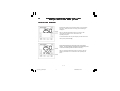
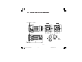
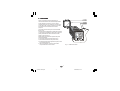
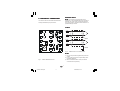
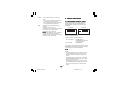
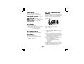
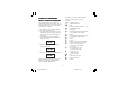
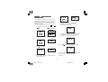
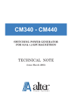
0216
0316
PID CONTROLLERS
U USER MANUAL
02_0316_A_DER.pmd
1
23/04/2004, 10.48
INDEX
GB
A . WHAT YOU NEED TO KNOW BEFORE YOU
S T A R T ................................................................... A . 2
A.1 OUTLINE AND CUT OUT DIMENSIONS ............. A.5
1 . MOUNTING .............................................................. 1
2 . ELECTRICAL CONNECTIONS ............................... 2
3 . PRELIMINARY HARDWARE
SETTINGS
6
4 . CONFIGURATION ................................................... 6
4.1 Pushbutton function ............................................ 6
4.2 Possible protection of the parameters ................ 6
4.3 Access to the configuration procedure ............... 7
4.4 Configuration parameters .................................... 7
5 . OPERATIVE MODE ............................................... 1 4
5.1 Preliminary comments ....................................... 14
5.2 SMART algorithm ............................................... 15
5.3 Inhibition of the out signal ................................. 15
5.4 Displaying the set point set
(model LDE) ........................................................ 16
5.5 SP/SP" selection ............................................... 16
5.6 Direct modification of the set point ................... 16
5.7 Timer mode description ..................................... 16
5.8 Manual reset of the alarm ................................. 20
5.9 Soft Start Ffunction ........................................... 20
5.10 Lamp test ........................................................... 20
5.11 Function of the pushbuttons ............................. 20
5.12 Indicators ........................................................... 21
5.13 Operative parameters ........................................ 21
6 . ERROR MESSAGES ............................................ 2 4
6.1 Measurement anomaly signal .......................... 24
6.2 Error messages ................................................. 25
6.3 List of possible errors ....................................... 25
7 . TECHNICAL CHARACTERISTICS ...................... 2 6
7.1 Technical specifications .................................... 26
7.2 Inputs ................................................................. 27
7.3 Control actions ................................................... 27
7.4 Outs ................................................................... 28
7.5 CPI - Configuration Port Interface ..................... 28
8 . MAINTENANCE ...................................................... 2 8
B . DEFAULT PARAMETERS .................................. B . 1
A. 1
02_0316_A_DER.pmd
2
23/04/2004, 10.48
A.
EUROTHERM CONTROLLER MODELS 0216 / 0316
What you need to know before you start
Home Screen Definition
Model 0216 displays the measured value or the operating
set point. When the timer is running, time remaining is
displayed.
LED “A” flashing indicates the timer is running, LED
“B” flashing indicates SP2 is selected as the
operating set point.
To select between the set point display and the measured
value press pushbutton V.
Model 0316 displays the measured value on the upper
display. The lower display indicates the operating set point
or the time remaining when the timer is running.
LED “A” flashing indicates the timer is running, LED “B”
flashing indicates SP2 is selected as the operating set
point.
A. 2
02_0316_A_DER.pmd
3
23/04/2004, 10.49
CONFIGURATION ENTRY & EXIT
DIRECT SETPOINT ENTRY
See page 16 section 5.6
While viewing the normal display hold either the
V or W button for more than 2 seconds. The
value will change. After reaching the new set
point do not press any keys for a further 2
seconds and the new value will be entered.
E n t r y See operator manual page 7 section 4.3
To gain access to configuration you need to be
in the HOME screen.
While in the HOME screen press the PAGE key
followed by the SCROLL key
Keep both keys pressed for 3 seconds until the
ConF.
display shows OFF and ConF
Now press either s or t to gain access by
changing OFF to ON
ON.
PARAMETER ENTRY
See page 21 section 5.11
Whenever a parameter is changed using either
the V or W buttons there are 2 options:
Exit
See operator manual page 14 after P28
To exit configuration you need to be at the Conf
screen
While in the Conf screen press the PAGE key
followed by the SCROLL key
Keep both keys pressed for 3 seconds until the
display returns to normal numeric display.
Accept new value
Press the SCROLL
key
Cancel the change Press the PAGE
key
LAMP TEST
POWER OUTPUT On/Off
See page 21 section 5.10
The instrument display LED’s can be tested as
follows:
These products allow you manually turn off the
output power.
See page 16 section 5.3
Activate Test Press W and
Press W and
Cancel Test
Off
To turn the power off press the V key
followed by the SCROLL
key.
Keep both buttons pressed for 3 seconds until
the display shows OFF.
On
To tune the power on press the V key
followed by the SCROLL
key.
Keep both buttons pressed for 3 seconds until
the display returns to normal numeric display.
A. 3
02_0316_A_DER.pmd
4
23/04/2004, 10.49
together
together
DEFAULT CONFIGURATION
TIMER CONTROL FROM FRONT
PANEL KEYS
See section B
The instrument can be pre-loaded with factory
default values.
Using the factory default values is ideal for
completely resetting the instrument before
commencing a new configuration.
See page 17 section 5.7
When a timer funtion is configured the
parameter ‘StS’ is enabled.
This parameter functions the same as that
described for a digital input.
‘StS’ = ‘OFF’ means that the time is off
PARAMETER SECURITY
‘StS’ = ‘On’ means that the timer is on.
See page 6 section 4.2, and page 10 section P11
& P14
The instrument is supplied with access to the
main parameters which are required for the set-up
procedure.
After commissioning it is necessary to select the
correct level of Parameter Security, simplifing the
instrument user interface for normal operation.
The most common security setting would be:
P11 = 1
P14 = Off
RECOVERY FROM A LOST
PASSWORD
See page 6 section 4.2, and page 10 section P11
& P14
If you lose your password
Enter Configuration using the Master Code of 408
Go to parameter P11 and enter the Master Code
of 408
You can now reset the password.
A. 4
02_0316_A_DER.pmd
5
23/04/2004, 10.49
A.1
OUTLINE AND CUT OUT DIMENSIONS
0216
EUROTHERM
0316
0 21 6
EUROTHERM
A. 5
02_0316_A_DER.pmd
6
23/04/2004, 10.49
0 31 6
1. MOUNTING
screws
bracket
gasket
panel
Select a mounting location where there is
minimum vibration and the ambient temperature
ranges between 0 and 50°C (32 and 122°F).
The instrument can be mounted on a panel up to
15 mm thick with a square cutout of 45 x 45 mm.
For outline and cutout dimensions refer to
page A.4.
The surface texture of the panel must be better
than 6.3 µm.
The instrument is fitted with a rubber panel gasket.
To assure IP65 and NEMA 4 protection, insert the
panel gasket between the instrument and the
panel as shown in Fig. 1.
While holding the instrument against the panel
proceed as follows:
1) insert the gasket in the instrument case;
2) insert the instrument in the panel cutout;
3) pushing the instrument against the panel, insert
the mounting bracket;
4) with a screwdriver, turn the screws with a
torque between 0.3 and 0.4 Nm.
GB
02-0316-1-DER.pmd
1
Fig. 1 PANEL MOUTING
1
22/04/2004, 16.19
2. ELECTRICAL CONNECTIONS
MEASURING INPUTS
NOTE
NOTE: Any external components (like zener
barriers etc.) connected between sensor and input
terminals may cause errors in measurement due
to excessive and/or not balanced line resistance or
possible leakage currents.
Connections are to be made with the instrument
housing installed in its proper location.
TC INPUT
+ 10
_ 9
Shield
+ 10
_ 9
+
Shield
Fig. 3
NOTES
NOTES:
1) Do not run input wires together with power line
cables.
2) For TC wiring use proper compensating cable
preferably shielded.
3) When a shielded cable is used, it should be
connected at one point only.
Fig. 2 REAR TERMINAL BLOCK
GB
02-0316-1-DER.pmd
THERMOCOUPLE CONNECTION
2
2
22/04/2004, 16.19
LOGIC INPUT
Safety note:
1) Do not run logic input wiring together with
power cables.
2) Use an external dry contact capable of
switching 8 mA, 8 V DC.
3) The instrument needs 300 ms to recognize a
contact status variation.
4) The logic input is NOT isolated by the
measuring input
RTD INPUT
RTD
8
9
RTD
10
8
9
Log. input 2
10
11
12
Fig. 4 RESISTANCE TEMPERATURE
DETECTOR CONNECTION
NOTES
NOTES:
1) Do not run input wires together with power line
cables.
2) Pay attention to the line resistance; a resistance
higher than 20 Ω/wire may cause measurement
errors.
3) When shielded cable is used, it should be
grounded at one side only to avoid ground loop
currents.
4) The impedence of the 3 wires must be the
same.
GB
02-0316-1-DER.pmd
3
Fig. 5 - LOGIC INPUT WIRING
The logic input can be programmed as:
A) Set point selector
A.1) In this case it will operate as follows:
logic input
operat. set point
open
SP
close
SP2
B) Start timer
In this case it will operate as described at
paragraph 5.7 (Timer modes description).
3
22/04/2004, 16.19
RELAY OUTS
3
OUT 1
2
1
3)
4)
NC
C
Use copper conductors only.
Do not run input wires together with power
line cables.
The following recommendations avoid serious
problems which may occur it when using relay
output to drive inductive loads.
NO
INDUCTIVE LOADS
OUT 2
6
7
OUT 3
15
14
C
High voltage transients may occur when switching
inductive loads.
These transients may introduce disturbances
through the internal contacts which can affect the
performance of the instrument.
The internal protection (varistors) assures correct
protection up to 0.5 A of inductive component but
the OUT 1 NC contact is not protected.
The same problem may occur when a switch is
used in series with the internal contacts.
NO
C
NO
Fig. 6 RELAY OUTS
C
The OUT 1 NO contact and the OUT 2 and OUT 3
contacts are protected by varistors against inductive
load with inductive component up to 0.5 A.
The OUT 1 contact rating is 3A/250V AC on
resistive load.
The OUT 2 and OUT 3 contact rating is 2A/250V
AC on resistive load.
The number of operations is 1 x 10⁵ at specified
rating.
02-0316-1-DER.pmd
4
POWER
LINE
LOAD
Fig. 7 EXTERNAL SWITCH IN SERIES WITH
THE INTERNAL CONTACT
In these cases an additional RC network should
be installed across the external contact as shown
in Fig. 7
The value of the capacitor (C) and resistor (R) are
shown in the following table.
NOTES:
1) To avoid electric shock, connect the power
line at the end of the wiring procedure.
2) For power connections use No 16 AWG or
larger wires rated for at least 75°C.
GB
R
4
22/04/2004, 16.19
R
(W)
P.
(W)
OPERATING
VOLTAGE
<40 mA 0.047 100
<150 mA
0.1
22
<0.5 A
0.33 47
1/2
2
2
260 V AC
260 V AC
260 V AC
POWER LINE WIRING
5
4
In every case the cable connected to the relay
outs must be routed as far away as possible from
input or communication cables.
OUT 1
+
_
1
SOLID STATE
RELAY
Fig. 8
SSR DRIVE OUT WIRING
It is a time proportioning out.
0 Vout < 0.5 V DC.
Logic level 0:
Logic level 1
1: Maximum current = 20 mA.
- 14 V + 20 % @ 20 mA
- 24 V + 20 % @ 1 mA.
NOTE
NOTE: This out is NOT isolated.
A double or reinforced Isolation between instrument
output and power supply must be assured by the
external solid state relay.
GB
02-0316-1-DER.pmd
5
R (S,T)
NOTES
NOTES:
1) Before connecting the instrument to the supply,
make sure that the line voltage corresponds to
that indicated on the rating plate.
2) To avoid electric shock, connect the power line at
the end of the wiring procedure.
3) For supply connections use No 16 AWG or larger
wires rated for at least 75°C.
4) Use copper conductors only.
5) Do not run input wires together with power line
cables.
6) For 24 V AC/DC the polarity does not matter.
7) The power supply input has NO fuse protection.
Please, provide a T type 1A, 250 V fuse externally.
8) The safety regulations for equipment
permanently connected to the mains require
that there is a switch or circuit breaker in the
building electrical system and that this:
- is near the device and can easily be reached by
the operator;
- is marked as the device ON/OFF device.
+
_
Power Line
100 V to 240 V AC (50/60Hz)
or 24 V AC/DC
Fig. 9 POWER LINE WIRING
VOLTAGE OUTS FOR SSR DRIVE
2
N
N
C
(mF)
R (S,T)
LOAD
(mA)
NOTE
NOTE: A single switch or circuit-breaker can drive
more than one instrument.
5
22/04/2004, 16.19
3 . PRELIMINARY HARDWARE
SETTINGS
4 . CONFIGURATION
4 . 1 PUSHBUTTON FUNCTION
This saves the new value of the
selected parameter and goes to the
next parameter (increasing order).
This scrolls back the parameters
without saving the new value.
This increases the value of the selected
parameter.
This decreases the value of the
selected parameter.
These instruments can detect the opening of the
input circuit (TC or RTD). This failure is displayed
as an overrange condition.
For the thermocouples only one can select, by
means of jumpers SH1 and CH1 indicated in Fig.
9, the type of indication to be obtained when the
thermocouple is open (see table at the bottom of
the page).
To gain access to the jumpers the instrument must
be taken out of its case.
4.2 POSSIBLE PROTECTION OF THE
PARAMETERS
Access to the configuration and the display and
modification of the operative parameters, can be
protected by a secret code. The code is entered in
configuration, by means of parameters P11 and
P14.
P11 = 0 All the operative parameters can be
displayed and modified. Access to the
configuration is free.
P11 = 1 and P14 = On All the operative
parameters can be displayed but not modified,
apart from SP (Set Point), SP2 (second set point)
and t (time of the timer function). Access to the
configuration is only possible by entering the
master key code when requested.
P11 = 1 and P14 = OFF No operative parameter
can be displayed and modified, apart from SP,
SP2 and t. Access to the configuration is only
possible by entering master key when requested.
P11 = 2/499 In this case the value programmed in
P11 represents a numerical key which can be
used to protect access to the configuration and, in
operative mode, the modification of the
SH1 CH1
Fig. 10 SH1 and CH1 JUMPERS
SH1
CH1
Indication
open
close
close
open
overrange (standard)
underrange
GB
02-0316-1-DER.pmd
6
6
22/04/2004, 16.19
parameters (SP, SP2 and t can always be
modified).
If the modification of the parameters has been
enabled, the passage in configuration is free.
If not it will be allowed by entering, when
requested, the numerical value programmed in
P11, or master key code.
P11 = 500/999 As for the previous point, with the
difference that alarm thresholds (AL and AL2) can
be modified as well as SP, SP2 and t.
numerical value (or the selection code). In the
model 0216, the display shows the parameter
code and the numerical value alternatively.
To alter the value set or the option selected press
or
and confirm with
.
The parameter for loading the default parameters
is shown in section B at the end of the manual.
4.4 CONFIGURATION PARAMETERS
In the two previous cases, with P14 = On, the
parameters set as not modifiable can however be
displayed. With P14 = OFF they are not.
To set P11 and P14 see section 4.4.
P1 - Type of input and standard range
Type of input
0 TC type L
1 TC type J
4.3 ACCESS TO THE CONFIGURATION
PROCEDURE
To access the configuration, press
and
simultaneously (press first
and immediately
afterwards
) keeping both the pushbuttons
pressed for three seconds.
In the model 0316 the lower display will show Cnf,
the upper OFF. In model 0216 OFF and CnF will
appear alternatively.
Press or within 10 seconds to set ON, then
confirm with
.
If the device is in the protected condition (see
previous section), the lower display (0316) shows
Cnf, the upper a dashed line (instead of OFF). In
model 0216 the two wordings appear alternately.
By means
or
enter the value entered in P11,
or master key value. Press
to confirm.
The instrument is now in configuration mode, and
the display shows Cnf steadily for both models.
Via
we advance to the first parameters.
2 TC type K
3 TC type N
4 RTD type Pt 100
5 RTD type Pt 100
6 TC type T
8 TC type L
9 TC type J
10 TC type K
11 TC type N
12 RTD type Pt 100
In configuration, the lower display shows the code
of the parameter (P1-P28), the upper the
GB
02-0316-1-DER.pmd
7
13 TC type T
Range
0 / +900 °C
0 / +999 °C
0 / +1000 °C
0 / +999 °C
0 / +1370
0 / +999 °C
0 / +1400 °C
-199 / +800 °C
-200 / +800 °C
-19.9 / +99.9 °C
-199.9 / +400.0 °C
0 / +400 °C
0 / 999 °F
0 / 1652 °F
0 / 999 °F
0 / 1832 °F
0 / 999 °F
0 / 2498 °F
0 / 999 °F
0 / 2552 °F
-199 / 999 °F
-328 / 1472 °F
0 / 752 °F
7
22/04/2004, 16.19
(0316)
(0216)
(0316)
(0216)
(0316)
(0216)
(0316)
(0216)
(0316)
(0216)
(0316)
(0216)
(0316)
(0216)
(0316)
(0216)
(0316)
(0216)
(0316)
(0216)
NOTE: When P1 has been changed, the P2 and
P10 parametrer will be forced to the minimum
value of the selected range while the P3 parameter
will be forced to the maximum value of the
selected range .
Reverse
t
t
P5 = Function of Out 2
0 = Not used or used as event (P27 = 3, 4, 6, 7)
1 = Alarm 1 output - Process alarm
2 = Alarm 1 output - Band alarm
3 = Alarm 1 output - Deviation alarm
4 = Alarm 1 output - Instrument failure alarm
5 = Cooling out
NOTES:
1) Setting P5 = 1, 2, 3:
- if parameter OLH is less than 0, it is set to
100;
- if parameter IP is less than 0, it is set to 30;
- if parameters AL1 is out of range, it will be
aligned to the lowest value.
2) Setting P5 = 0 or 4:
- if parameter OLH is less than 0, it is set to 100;
- if parameter IP is less than 0, it is set to 30;
3) Setting P5 = 5:
- parameter P4 automatically assumes the
value “rEU”;
- if parameter P16 is out of range, it will be
aligned to the lowest value;
- if parameter Pb is not 0 and is lower than 1.5,
it is set to 1.5.
4) Setting P5 different 0:
- if P27 parameter is equal to 3, 4, 6 or 7 it will
be forced to 0.
NOTES
NOTES:
1) The minimum input span (P3 - P2) is 300°C or
600°F for TC input and 100°C or 200°F for RTD
input.
3) When P3 has been modified, the rH parameter
will be aligned to it and rl parameter will be
forced to P2 value is rl > rH.
4) When P3 has been modified, if the alarms are
programmed as process alarms (P5=1 and/or
P22=1) and the alarm thresholds are out of
range, AL.1 and/or AL. 2 will be aligned to P3.
P4 = Out 1 action
This parameter is not modifiable when P5 = 5
rEU = reverse action (Heating)
dir = direct action (Cooling)
8
t
Out
t
P3 = Full scale value
Full scale value for input from thermocouple/
Resistance Temperature Detector.
02-0316-1-DER.pmd
Input
Out
P2 = Initial scale value
Initial scale value for input from thermocouple/
Resistance Temperature Detector.
NOTES
NOTES:
1) When P2 has been modified, the rL parameter
will be aligned to it and rH parameter will be
forced to P3 value is rH < rL.
2) When P2 has been modified, if the alarms are
programmed as process alarms (P5=1 and/or
P22=1) and the alarm thresholds are out of
range, AL.1 and/or AL. 2 will be aligned to P2.
GB
Direct
Input
8
22/04/2004, 16.19
P8 = Stand-by of the alarm 1
Only available when P5 is 1, 2 or 3.
OFF = stand-by disabled
ON = stand-by enabled
NOTE
NOTE: For band or deviation alarm, the alarm
stand-by function disables the alarm indication at
instrument start up and after a set point
modification until the process variable reaches the
alarm threshold.
For process alarm, the stand-by function is
activated at start up only.
P6 = Out 2 configuration
P6 is skipped when P5 = 0.
If P5 = 1, 3 or 4;
H.A. = High alarm with automatic reset
L.A. = Low alarm with automatic reset
H.L. = High alarm with manual reset
L.L. = Low alarm with manual reset
When P5 = 4, the "high" or "low" selection has no
effect.
If P5 = 2:
HA
. . = out of band with automatic reset
L.A. = in band with automatic reset
H.L. = out of band with manual reset
L.L. = in band with manual reset
P9 = OFFSET applied to the measured value
This OFFSET is applied along the whole span.
When P1= 5
P9 is programmable from -19.9
to 19.9°C.
When P1 ≠ 5
P9 is programmable from -199
to 199°C or °F.
When P5 = 5 this parameter selects the cooling
medium.
AIr = air
OIL = oil
H2O = water
Readout
NOTE
NOTE: Modifying parameter P6 automatically
updates the values of the cooling cycle time and
the cooling gain.
P6
Air
OIL
H2O
C2
10 (s)
4 (s)
2 (s)
P9
RC
1
0.8
0.4
GB
9
Adjusted
curve
Input
P10 = Threshold of the “Soft Start” function
The “Soft start” function limits the maximum out
power (see OLH operative parameter) for a
programmable time (see tOL operative parameter)
at the instrument start up when the measured
value is lower then the programmed threshold.
P10 is the threshold value, in engineering units.
Changing P1 parameter value, P10 parameter will
be forced to the minimum range value of the new
selected range.
P7 = Alarm 1 action
Only available when P5 is different from 0 or 5.
rEU = reverse (relay de-energized in alarm
condition)
d i r = direct (relay energized in alarm condition)
02-0316-1-DER.pmd
Real curve
9
22/04/2004, 16.19
P 1 1 = Safety lock
0=
No parameter protection.The device is
always in “unlock” condition and all the
parameters can be always modified.
1=
None parameter, with the exception of
parameters from SP to t , can be modified.
2/499 = This combination numberis a secret
value, to be used in operative mode, to place
the device from the “lock” to the “unlock”
condition (the parameters from SP to t are not
subjected to the lock/unlock rule)
500/999 = This combination number is a secret
value, to be used in operative mode, to place
the device from the “lock” to the “unlock”
condition (the parameters from SP to t and
AL.1 – AL.2 are not subjected to the
lock/unlock rule)
P 1 2 = Out maximum rate of rise
This limit will be used if Pb is different from 0
only.
Programmable from 1 to 25% of the out signal
per second.
Over 25%/s the instrument displays “InF” to
indicate the exclusion of the limitation.
This limit have no effect if the selected contol
algorithm is ON/OFF type (PB=0)
P13 – FILTER ON INPUT MEASURE
OFF = Filter disabled
On = Filter enabled
P14 = Protected parameters display
This parameter is available if P11 is not 0.
This parameter enables/disables the display of
the protected parameter during "operative mode".
OFF = the protected parameters are not
displayed
ON = the protected parameters are displayed
GB 10
02-0316-1-DER.pmd
10
P 1 5 - SMART function enabling/
disabling
0 = The SMART function is disabled
1 = SMART function enabling/disabling is
NOT protected by the safety code.
2 = SMART function enabling/disabling is
protected by the safety code.
P16 - Maximum value of the proportional band
automatically settable by the
SMART function
This parameter is available if P15 is not 0. It can
assume the following values:
model 0316: between P17 or P18 and 99.9%
model 0216: between P17 or P18 and 100.0%
P17 - Proportional minimum band value
automatically settable by the
SMART function ( one control out
only)
This parameter is only displayed if P5 is not 5 and
P15 is not 0.
It may be programmed from 1.0% to the value of
P16.
P 1 8 - Proportional minimum band value
automatically settable by the
SMART function (two control outs,
heating/cooling)
This parameter is only present if P5 is 5 and P15
is not 0.
This parameter may be programmed from 1.5%
to the value of P16.
22/04/2004, 16.19
P 1 9 = Automatic calculation of
"relative cooling gain"
This parameter is only present if P5 is 5 and P15
is not 0.
OFF = the SMART function does NOT
calculates the "relative cooling gain".
ON = the SMART function calculates the
"relative cooling gain".
P 2 0 = Minimum integral time value
calculated by the SMART function
This parameter is only present if P15 is not 0.
It can assume the following values:
model 0316: between 0.1 (10 seconds) and 2.0 (2
minutes)
model 0216: between 00.01 (1 second) and 2.00
(2 minutes).
P 2 1 = Extension of the anti-reset-wind
up
Span: from -30 to +30 % of the proportional
band.
NOTE
NOTE: a positive value increases the high limit
of the anti-reset-wind up (over set point) while a
negative value decreases the low limit of the
anti-reset-wind up (under set point).
P22 = OPTION FEATURE(Out3 or
digital input)
0=Output not provided
1=Out3 used as Alarm 2 output – Process alarm
2=Out3 used as Alarm 2 output – Band alarm
3=Out3 used as Alarm 2 output –Deviation alarm
4=Digital input enabled
NOTE
NOTE: Select option feature in according to
mounted HW circuitry.
None automatic recognize is provided
When P22 = 1, 2, 3 the parameter AL2 will be
checked and set to its low limit if out of range
P23 = Alarm 2 configuration
P23 is skipped when P22 is equal to 0
If P22 = 1 or 3
H.A. = High alarm with automatic reset
L.A. = Low alarm with automatic reset
H.L. = High alarm with manual reset
L.L. = Low alarm with manual reset
If P22 = 2:
H.A. = out of band with automatic reset
L.A. = in band with automatic reset
H.L. = out of band with manual reset
L.L. = in band with manual reset
P24 = Alarm 2 action
P24 is available when P22 is 1, 2 or 3.
rEU = reverse (relay de-energized in alarm
condition)
dir = direct (relay energized in alarm condition)
P25 = Stand-by of the alarm 2
P25 is available when P22 is 1, 2 or 3.
OFF
= stand-by disabled
ON
= stand-by enabled
NOTE
NOTE: The alarm stand-by function disables the
alarm indication at instrument start up and after a
set point modification until the process variable
reaches the alarm threshold.
P26 = Not used
GB 11
02-0316-1-DER.pmd
11
22/04/2004, 16.19
P27 – FEATURE FUNCTION
0 = None
1 = SP/SP2 selection
2 up to 5 = Timer function (for SP/SP2
selection)
6 up to 8 = Timer function (for enable/disable
control output)
(see Timer Function description)
When P27 = 1, 2, 5 the parameter sp2 will be
checked and set to rL if out of range
When P27 = 3, 4 the parameter sp2 will be
checked and set to rL if out of range and
parameter P5 is forced to 0
When P27 = 6,7 the parameter P5 is forced to 0
When P27 is < 6 and it was >= 6, the control
Timer mode 2 [P27 = 3]
When the contact is closed, the instrument
controls using SP as operative set point.
When the contact has been opened the
instrument selects SP2 as operative set point
and starts the time count down.
NOTE: that the guarantee soak function can be
applied to this timer mode (see P28 parameter)
When the time count is equal to 0 the instrument
comes back to the SP set point and the output 2
will be energized.
The Out 2 reset will be made when the logic input
will be closed again.
For other details see paragraph "5.7 Timer
modes description".
output is forced “enable” at the next start-up.
Timer functions
Notes about all timer modes:
1) At power off the time value and status will be reset.
2) The time parameter (t) can always be modified
but the new value become operative at the
next start time only.
Timer mode 1 [P27 = 2]
If the logic input remains in open condition for
more than a programmed time the instrument
goes automatically at a stand by temperature
(SP2).
The time count is reset when the logic input is
closed.
Timer mode 3 [P27 = 4]
When the contact is closed, the instrument
controls using SP as operative set point.
When the contact has been opened the
instrument operate as follows:
- it selects SP2 as operative set point
- it starts the time count down
- it energizes the Output 2
NOTE: that the guarantee soak function can be
applied to this timer mode (see P28 parameter)
When the time count is equal to 0 the instrument
comes back to the SP set point and the output 2
will be reset.
For other details see paragraph "5.7 Timer
modes description".
For other details see paragraph "5.7 Timer
modes description".
GB 12
02-0316-1-DER.pmd
12
22/04/2004, 16.19
Timer mode 4 [P27 = 5]
The instrument operates using SP set point and
the timer is normally reset.
When the instrument detects the transfer from
contact open to close it selects SP2 as operative
set point and starts the time count down.
NOTE: that the guarantee soak function can be
applied to this timer mode (see P28 parameter)
When the time count is equal to 0 the instrument
comes back to the SP set point.
For other details see paragraph "5.7 Timer
modes description".
Timer mode 5 [P27 = 6]
The instrument start in "Power OFF" mode and it
remains in "Power OFF" mode until the contact is
closed.
When the contact has been opened the instrument
starts the control using SP set point and starts the
time count down.
NOTES:
1) The guarantee soak function can be applied to
this timer mode (see P28 parameter)
2) The transfer from "Power OFF" mode to
AUTOMATIC mode starts the "Soft start" and
the "alarm masking" functions (if programmed).
When the time count is equal to 0 the instrument
comes back to the "Power OFF" mode and the
output 2 will be energized.
The Out 2 reset will be made when the logic input
will be closed.
Timer mode 6 [P27 = 7]
The instrument starts in "Power OFF" mode and
it remains in "Power OFF" mode until the contact
is closed.
When the contact has been opened the
instrument operate as follows:
- it starts the control using SP set point.
- it starts the time count down
- it energizes the Output 2
NOTES:
1) The guarantee soak function can be applied to
this timer mode (see P28 parameter)
2) The transfer from "Power OFF" mode to
AUTOMATIC mode starts the "Soft start" and
the "alarm masking" functions (if programmed).
When the time count is equal to 0 the instrument
comes back to the "Power OFF" mode and the
output 2 will be reset.
For other details see paragraph "5.7 Timer
modes description".
For other details see paragraph "5.7 Timer
modes description".
GB 13
02-0316-1-DER.pmd
13
22/04/2004, 16.19
Timer mode 7 [P27 = 8]
The instrument starts in "Power OFF" mode and
it remains in "Power OFF" mode until a transfer
from open to close of the logic input is detected.
When the instrument detects the transfer from
contact open to close it starts the control using SP
set point and starts the time count down.
NOTES:
1) The guarantee soak function can be applied to
this timer mode (see P28 parameter)
2) The transfer from "Power OFF" mode to
AUTOMATIC mode starts the "Soft start" and
the "alarm masking" functions (if programmed).
When the time count is equal to 0 the instrument
comes back to the "Power OFF" mode .
For other details see paragraph "5.7 Timer
modes description".
P28 – BAND FOR TRACK
(Present if P27 is greater than 2)
0.1 / 50.0 for input range 5
1 / 500 for all other input ranges
Above max value the display shows
“OFF” meaning that the tracking is
disabled
5 . OPERATIVE MODE
The display and modification of the operative
parameters can be protected by a secret code.
For more information see section 4.2.
5 . 1 PRELIMINARY COMMENTS
It is assumed, at this point, that the instrument
has been correctly configured as indicated in
Section 4.
- Model 0316 displays the measured value on the
upper display: the lower display is normally
used to display the operating set point (below
this condition is defined as “Normal display”) or
the remaining time (when the timer is running).
- Model 0216 displays:
- the measured value (below this condition is
defined as “Normal display”) or
- the operating set point (in this case the SP
led lights up) or
- the remaining time when the timer is running
(in this case the decimal point on the left hand
the LSD will flash).
To change from the display of the set point to
that of the measured value, or vice versa, press
pushbutton .
All the parameters can be displayed sequentially
by pressing the
pushbutton.
- Model 0316 displays the abbreviated name of
the selected parameter on the lower display, on
the upper it will display the selected value.
- Model 0216 displays alternately the name of
the parameter and its value: during the
modification it displays only the value.
GB 14
02-0316-1-DER.pmd
14
22/04/2004, 16.19
5 . 2 SMART ALGORITHM
This function gives best process control.
To enable the SMART function, press the
pushbutton for more than 1.5 s, when the
instrument is in normal display mode. The SMT
LED will be lit continuously or flash according to
the algorithm automatically selected.
When the SMART function is enabled, the control
parameters (PB,, TI,, TD and rC) can be displayed
but not modified.
When it is dasired to disable the SMART function,
press the
pushbutton again (for more than
1.5 s) to turn the "SMART" OFF. The instrument
maintains the actual control parameters setting
and allows parameter modification.
NOTES
NOTES:
1) During operation of the SMART function, the
relative cooling gain (if controlled by SMART) is
limited within the following ranges:
Cooling medium
Span
Air
0.85 to 1.00
OIL
0.80 to 0.90
H2O
0.30 to 0.60
2) The SMART function uses a derivative time equal
to 1/4 of the integral time.
3) The limits of the proportional band settable by
the SMART function are programmed by
parameters P16, P17 and P18 .
4) The lower limit of the integral time settable by
the SMART function is programmed by
parameter P20 .
5) When ON/OFF control is programmed (Pb=0),
the SMART function is disabled.
6) SMART enabling/disabling can be protected by
the safety lock (see parameter P15).
5 . 3 INHIBITION OF THE OUT SIGNAL
(Power OFF mode)
Keeping depress for more than 3 s the
+
pushbuttons with device in normal display mode
it is possible to enable/disable the control output
(this function is not subject to lock/unlock rule)
When control output is disabled:
•
The device will function as an indicator
and the “OFF” indication appears on the
display (with device in Normal display
mode).
•
The Out 1 goes OFF.
•
The Out 2 goes OFF if it is configured as
cooling output (P5 = 5), while it is forced
in no alarm condition if it is configured as
process, band or deviation alarm (P5 = 1
or 2 or 3).
It works normally if configured as measure
malfunctioning annunciator (P5 = 4) or
event
annunciator (P27 = 3, 4, 6, 7)
•
The Out 3 it is forced in no alarm condition
if it is configured as process, band or
deviation alarm ( P22 = 1 or 2 or 3)
•
The self tuning algorithm cannot be turn
on/turn off. If Adaptive is in act the
algorithm is frozen and restarts
automatically when control output is
restored.
When control is restored the functions alarms
standby, soft start and control output rate of
rise will be activated as per power up.
The enable/disable control status is stored in
EEprom.
GB 15
02-0316-1-DER.pmd
15
22/04/2004, 16.19
The control output is always disabled
(OFF) at power up
5 . 4 DISPLAYING THE SET POINT SET
(model 0216)
To display the set point set, press the
pushbutton. The SP led lights up.
The set point value will appear on the display.
To return to the display of the value measured
press pushbutton again.
5.5 SP/SP2 SELECTION
When P27 = 0 the set point 2 is not avaiable.
When P27 = 1, it is possible to select the operating
set point (SP or SP2) by the logic input only (terminals 11 and 12).
When P27 > 1 the set point selection is managed
by timer function and no manual selection is
available
5 . 6 DIRECT MODIFICATION OF
THE SET POINT
The instrument allows to modify the selectedc
set point value without to use the
pushbutton.
When direct access to the selected set point
modification is required, proceed as follow:
1) Press pushbutton or for more than
2 seconds; the set point value will be
displayed and it will start to change.
2) Using the
and
pushbuttons, set the
desired value.
GB 16
02-0316-1-DER.pmd
16
3)
When the desired value is reached, DO NOT
press any pushbutton, the new set point will
become operative after 2 seconds after the
pushbuttons were last pressed and the
instrument will return to the “normal display”.
If during this procedure the modification is not to
be saved, press the
pushbutton immediately
(within 2 seconds); the instrument automatically
returns to the normal display without saving the
new set point.
5.7 Timer modes description
Timer mode 1 [P27 = 2]
If the logic input remains in open condition for more
than a programmed time the instrument goes
automatically to a stand by temperature (SP2).
The time count is reset when the logic input is
closed.
0316 display management
management: the upper display
shows the measured value while the lower
display shows the operative set point.
0216 display management
management: the display
shows the measured value.
Pushing
pushbutton it is possible to display
the operative set point.
SP
Programmed
time
If P27 = 6, 7, 8 the enabling/disabling of control
output is not controlled by keyboard but
through logic input and timer.
. In this case the control status is not
stored in EEprom.
SP2
Time
Logic input
Closed
Open
Open
22/04/2004, 16.19
Closed
Timer mode 2 [P27 = 3]
When the contact is closed, the instrument
controls using SP as operative set point.
When the contact has been opened, the
instrument selects SP2 as operative set point
and starts the time count down.
When the time count is equal to 0 the instrument
comes back to the SP set point and the output 2
will be energized.
The Out 2 reset will be made when the logic input
will be closed again.
0316 display management
management: when the instrument
starts the time count down, the upper display
shows the measured value while the lower display
shows time count down.
0216 display management
management: when the
instrument starts the time count down, the
display shows the time count down.
Pushing pushbutton it is possible to display the
measured value.
NOTE
NOTE: for both instruments, when the time is
finished the instrument comes back to the normal
display mode.
SP2
Timer mode 3 [P27 = 4]
When the contact is closed, the instrument
controls using SP as operative set point.
When the contact has been opened the
instrument operates as follows:
- it selects SP2 as operative set point
- it starts the time count down
- it energizes the Output 2
When the time count is equal to 0 the instrument
comes back to the SP set point and the output 2
will be reset.
0316 display management
management: when the instrument
starts the time count down, the upper display
shows the measured value while the lower display
shows time count down.
0216 display management
management: when the
instrument starts the time count down, the
display shows the time count down.
Pushing
pushbutton it is possible to display
the measured value.
NOTE
NOTE: for both instruments, when the time is
finished the instrument comes back to the normal
display mode.
SP2
Programmed
time
SP
SP
Time
Stop
Run
Stop
Run
Stop
Time
Run
Contact
Paint
Dry
Paint
Dry
Paint
Dry
Contact
Closed
Open
Closed
Open
Closed
Output 2
Open
Closed
Open
Output 2
OFF
OFF
ON
OFF
OFF
ON
GB 17
02-0316-1-DER.pmd
17
22/04/2004, 16.19
OFF
Timer mode 4 [P27 = 5]
The instrument operates using SP set point and
the timer is normally reset.
When the instrument detects the transfer from
contact open to close it selects SP2 as operative
set point and starts the time count down.
When the time count is equal to 0 the instrument
comes back to the SP set point.
0316 display management
management: when the
instrument starts the time count down, the upper
display shows the measured value while the
lower display shows time count down.
0216 display management
management: when the
instrument starts the time count down, the
display shows the time count down.
Pushing
pushbutton it is possible to display
the measured value.
NOTE
NOTE: for both instruments, when the time is
finished the instrument comes back to the normal
display mode.
Timer mode 5 [P27 = 6]
The instrument start in "Power OFF" mode and it
remains in "Power OFF" mode until the contact is
closed.
When the contact has been opened the
instrument starts the control using SP set point
and starts the time count down.
When the time count is equal to 0 the instrument
comes back to the "Power OFF" mode and the
output 2 will be energized.
The Out 2 reset will be made when the logic input
will be closed.
0316 display management
management: when the instrument
starts the time count down, the upper display
shows the measured value while the lower display
shows time count down.
0216 display management
management: when the instrument
starts the time count down, the display shows the
time count down.
Pushing
pushbutton, it is possible to display
the measured value.
NOTE
NOTE: for both instruments, when the time is
finished the instrument comes back to the usual
display of the Power OFF mode.
SP
Output
Power
OFF
SP2
Output
Power
OFF
Time
Stop
SP
Run
Stop
Run
Stop
Run
Contact
Closed
Time
Logic input
Open
Closed
Open
Open
Open
OFF
OFF
GB 18
02-0316-1-DER.pmd
18
Closed
Open
Output 2
22/04/2004, 16.19
ON
OFF
Timer mode 6 [P27 = 7]
The instrument starts in "Power OFF" mode and
it remains in "Power OFF" mode until the contact
is closed.
When the contact has been opened the instrument
operates as follows:
- it starts the control using SP set point.
- it starts the time count down
- it energizes the Output 2
When the time count is equal to 0 the instrument
comes back to the "Power OFF" mode and the
output 2 will be reset.
0316 display management
management: when the instrument
starts the time count down, the upper display
shows the measured value while the lower display
shows time count down.
0216 display management
management: when the instrument
starts the time count down, the display shows the
time count down.
Pushing pushbutton, it is possible to display the
measured value.
NOTE
NOTE: for both instruments, when the time is
finished the instrument comes back to the usual
display of the Power OFF mode.
Timer mode 7 [P27 = 8]
The instrument starts in "Power OFF" mode and
it remains in "Power OFF" mode until a transfer
from open to close of the logic input is detected.
When the instrument detects this transfer, it starts
the control using SP set point and starts the time
count down.
When the time count is equal to 0 the instrument
comes back to the "Power OFF" mode .
0316 display management
management: when the instrument
starts the time count down, the upper display
shows the measured value while the lower display
shows time count down.
0216 display management
management: when the instrument
starts the time count down, the display shows the
time count down.
Pushing
pushbutton, it is possible to display
the measured value.
NOTE
NOTE: for both instruments, when the time is
finished the instrument comes back to the usual
display of the Power OFF mode.
SP
Output
Power
OFF
Output
Power
OFF
Time
Stop
Run
Stop
Run
Stop
SP
Run
Contact
Closed
Open
Output
Power
OFF
Closed
Open
Output
Power
OFF
Time
Contact
Output 2
OFF
ON
OFF
Open
Closed
Open
GB 19
02-0316-1-DER.pmd
19
22/04/2004, 16.19
Open
5 . 8 MANUAL RESET OF THE ALARM
If the alarm has been configured as a latched
alarm, the alarm status persists even after the
alarm condition disappears.
To reset the alarm, press the
pushbutton to
select the parameter “n.rS” (the display will show
“n.rS” and “OFF”. Use the
and
pushbuttons to select “ON” and press the
pushbutton.
The alarm reset action will only be successful if
the alarm condition has disappeared only.
SP/SP2 or TIMER CONTROL
(This parameter is skipped if P27 is = 0)
Lower display:
stS
Upper display:
OFF = Status OFF
5.9 “Soft Start” FUNCTION
At power up, the instrument will measure the
process variable and compare the measured
value with a programmed threshold (see P10
parameter in chapter 4).
If the measured value is lower than the programmed value, the instrument will limit the
maximum output power (see OLH operative
parameter) for a programmed time (see tOL
operative parameter).
If tOL is equal to InF, the limiter is ever active.
5.10 LAMP TEST
To check the display efficiency, press pushbuttons
+
. The instrument will turn ON, with a
50% duty cycle, all the LEDs of the display (this
state is called LAMP TEST).
No time out is applied to the LAMP TEST.
To return to the normal display mode, press
pushbuttons
+
again.
No other keyboard functions are available during
the LAMP TEST.
- On = Status ON
5.11
FUNCTION OF THE
PUSHBUTTONS
Saves the new value of the selected
parameter and goes to the next
parameter (increasing order).
Enables or disables the SMART
function and scrolls back all the
parameters without saving them.
Increases the value of the selected
parameter or (0216 only) displays the
set point value or the measured
value.
Decreases the value of the selected
parameter.
GB 20
02-0316-1-DER.pmd
20
22/04/2004, 16.19
5.12
INDICATORS
SMT Flashes when the first part of the SMART
algorithm is active.
Lit when the second part of the SMART
algorithm is active.
OUT1 Lit up when out 1 is ON.
OUT2 A) When used as event or cooling output it
lit up when out 2 is ON.
B) When used as alarm indication:
B.1) Lit if only Alarm1 is in alarm
condition.
B.2) Flashing at slow rate (0.5 Hz) if only
Alarm 2 is in alarm condition.
B.3) Flashing at fast rate ( 2 Hz) if both
alarms are in alarm condition.
°C
Lit up if the temperature is displayed in °C.
°F
Lit up if the temperature is displayed in °F.
SP
(0216 only) Lit when the display shows the
operative set point.
In addition
addition:
a)
The decimal point on the right hand of the
LSD of the upper display, for 0316, or of
the display, for 0216, flashes when the
instrument is working with SP2.
b)
The decimal point on the left hand of the
LSD of the lower display, for 0316, or of the
display, for 0216, flashes when the display
shows the time count down.
5.13
OPERATIVE PARAMETERS
The following is a list of all the available control
parameters.
Note that some parameters may not be displayed
depending on the specific instrument
configuration.
To modify the setting of a parameter proceed as
follows:
1) By means of the
pushbutton select the
parameter to be modified.
2) Using the and
keys set the value
required.
3) Press the
pushbutton to save the new
value and go to the next parameter.
4) Press
to return to the previous parameter
without saving.
NOTES
NOTES:
1) If, during parameter modification, no
pushbutton is pressed for more than 10
seconds, the instrument automatically reverts
to the “normal display mode” and the new
setting of the last parameter will be lost.
2) The instrument does not display all the
possible parameters, but only those which are
in agreement with:
a) The instrument configuration (see section
4).
b) The setting of parameter P14 (see section
4).
c) The setting of the proportional band (see
section 5.5).
GB 21
02-0316-1-DER.pmd
21
22/04/2004, 16.19
Param. Description
SP
Set point (in eng. units).
Span: from rL to rH.
n.rS
Manual reset of the alarms.
This parameter is displayed if one alarm
has been programmed with manual
reset.
Set ON and press the
pusbutton to
reset the alarms.
Sts
SP2
t
nnn
AL.1
SP/SP2 or TIMER CONTROL
OFF
Set point 2 (in eng. units).
This parameter is present if P27 = 1, 2,
3, 4 or 5.
Span: from rL to rH.
time of the timer function (in minutes
and seconds).
This parameter is present if P27 greater
than 2.
Span: from 10 seconds (00.1) to 90
minutes (90.0).
Software key for parameter protection.
This parameter is skipped if P11 = 0 or 1.
ON = the instrument is in LOCK
condition
OFF = the instrument is in UNLOCK
condition.
To switch from LOCK to UNLOCK, set a
value equal to the value of parameter
P11.
To switch from UNLOCK to LOCK, set a
value different from the value of
parameter P11.
Span: 2/999
Alarm 1 threshold (in eng. units).
This parameter is available only if
P5 = 1, 2 or 3.
Spans:
- From P2 to P3 for process alarm
(P5 = 1)
HS.1
AL.2
HS.2
Pb
- From 0 to 500 units for band alarm
(P5 = 2).
- From -199 to 500 units for deviation
alarm (P5 = 3).
Alarm 1 hysteresis (in % of P3 - P2
span).
This parameter is available only if
P5 = 1, 2 or 3.
Span: From 0.1% to 10.0% of the input
span or 1 LSD.
NOTE
NOTE: If the hysteresis of a band alarm
is larger than the alarm band, the
instrument will use an hysteresis value
equal to the alarm band minus 1 digit.
Alarm 2 threshold (in eng. units).
This parameter is available only if
P22 = 1, 2 or 3.
Spans:
- From P2 to P3 for process alarm
(P5 = 1)
- From 0 to 500 units for band alarm
(P5 = 2).
- From -199 to 500 units for deviation
alarm (P5 = 3).
Alarm 1 hysteresis (in % of P3 - P2
span).
This parameter is available only if
P22 = 1, 2 or 3.
Span: From 0.1% to 10.0% of the input
span or 1 LSD.
NOTE
NOTE: If the hysteresis of a band alarm
is larger than the alarm band, the
instrument will use an hysteresis value
equal to the alarm band minus 1 digit.
Proportional band (in % of P3 - P2 span).
Span:
- For one control output: from 1.0% to
99.9% (from 1.0% to 100.0% for
model 0216) of the input span (P3-P2).
GB 22
02-0316-1-DER.pmd
22
22/04/2004, 16.19
HS
t i
td
- For two control outputs: from 1.5% to
99.9% (from 1.5% to 100.0% for model
0216) of the input span (P3-P2)
When the the SMART is ON (see section
5.2) the value of Pb is limited to that set
in P16-P17 (one control action) and to
that set on P16-P18 (two control actions).
When Pb parameter is set to 0, the
instrument performs an ON-OFF control;
the ti, td, IP, C, C2, rC, OLP, OLH and
tOL parameters are skipped and the
"output max. rate of rise" and SMART
functions are not available.
Hysteresis for ON/OFF control action (in
% of P3 - P2 span).
This parameter is only available when
Pb = 0.
Span: from 0.1% to 10.0% of the input
span.
Integral time. Is skipped when Pb = 0
(ON/OFF action).
Span model 0316: from 0.1 to 20.0 mm.s
(minutes and tens of seconds).
Span model 0216: from 00.01 to
20.00 mm.ss (minutes and seconds)
Above this value the display becomes
dark and the integral action is excluded.
Derivative time. This parameter is
skipped if Pb = 0 (ON/OFF action).
Span model 0316: from 0.00 to 9.59
mm.ss (minutes and seconds)
Span model 0216: from 0.00 to 10.00
mm.ss (minutes and seconds).
If 0 is set, the derivative action is
excluded.
IP
C
C2
rC
OLP
rL
rH
Integral pre-load. This parameter is only
available when Pb is not 0.
Span:
- from 0 to 100% for one control output
- from -100 to 100% for two control
outputs.
Out 1 cycle time (in seconds).
This parameter is only available when
Pb is not 0.
Span: from 1 to 200 s.
Out 2 cycle time (in seconds).
C2 is only available if Pb is not 0 and P5
is 5.
Span: from 1 to 200 s.
Relative Cooling gain.
This is skipped if Pb = 0 (ON/OFF action)
or P5 is not 5.
Span: from 0.20 to 1.00
Dead band/Overlap between H/C outs (in
% of the proportional band).
“OLP” is skipped if Pb = 0 (ON/OFF
action) or P5 is not 5.
A negative value shows a dead band
while a positive value shows an overlap.
Span: from -20 to 50%.
Set point low limit (in eng. units).
Span: from min. range value (P2) to rH.
NOTE
NOTE: when rL value has been
chenged, if the SP and SP2 value are
lower than the new rL value, thay will be
alligned to the new rL value.
Set point high limit (in eng. units).
Range:from rL to full scale value (P3).
NOTE
NOTE: when rH value has been
chenged, if the SP and SP2 value are
higher than the new rH value, thay will
be alligned to the new rH value.
GB 23
02-0316-1-DER.pmd
23
22/04/2004, 16.19
OLH
tOL
Out maximum limit (in % of the out).
Span:
- From 0 to 100 when the instrument is
configured with one control out.
- From -100 to 100 when the instrument
is configured for two control outs.
Duration of the out power limiter (in
minutes).
Available only if Pb is not 0.
Span: from 1 to 540 min. Above this limit,
the display shows "Inf" and the
limitation is always entered.
NOTE
NOTE: Parameter tOL can be modified
but the new value will only become
operative at the next instrument start up
unless the new value is Inf.
6 . ERROR MESSAGES
6.1 MEASUREMENT ANOMALY SIGNAL
The instrument display (the upper display for
model 0316) shows the OVERRANGE and
UNDERRANGE conditions with the following
indications:
Overrange
Underrange
The example shows the display of model 0316.
Model 0216 displays 4 digits.
The sensor break can be signalled as:
- for TC/mV input
: OVERRANGE or
UNDERRANGE selected
by a solder jumper
- for RTD input
: OVERRANGE
On RTD input, a special test is provided to signal
OVERRANGE when input resistance is less than
12 ohm (Short circuit sensor detection).
NOTE
NOTE:
When:
- The instrument is set for one control out only
and an OVERRANGE is detected, the OUT 1
turns OFF (if reverse action) or ON (if direct
action).
- The instrument is set to use two control outs
and an OVERRANGE is detected, OUT 1 turns
OFF and OUT 2 turns ON.
- The instrument is set for one control out only
and an UNDERRANGE is detected, the OUT 1
turns ON (if reverse action) or OFF (if direct
action).
GB 24
02-0316-1-DER.pmd
24
22/04/2004, 16.19
- The instrument is set to use two control outs
and an UNDERRANGE is detected, OUT 1 turns
ON and OUT 2 turns OFF.
For inputs from thermocouple the underrange
indication can be selected as shown in section 7.2
of this manual.
NOTE: When an overrange or an underrange is
detected, the alarms operate as if the
instrument had detected the maximum or
the minimum measurable value
respectively.
To eliminate the out of span condition, proceed as
follows:
1) Check the input signal source and the
connecting line.
2) Make sure that the input signal is in
accordance with the instrument configuration.
Otherwise, modify the input configuration (see
section 4).
3) If no error is detected, send the instrument to
your supplier to be checked.
6 . 2 ERROR MESSAGES
Diagnostics are made on switching on and during
normal operation.
If the instrument detects an error condition the
display will show:
0316: “Err” in the lower display and the code
which identifies the type of error in the
upper display.
0216: “E” and the error code.
6 . 3 LIST OF POSSIBLE ERRORS
100
EEPROM writing error.
Consult your supplier.
2xx
Error in the configuration parameters.
The two less significant figures indicate
the number of the incorrect parameter
(e.g. 209 Err indicates error of
parameter P9).
Press
and
, then set the
parameter correctly.
See section 4.
301
RTD input calibration error.
Contact your supplier.
305
TC input calibration error.
Contact your supplier.
307
RJ input calibration error.
Contact your supplier.
Error in the operative parameters.
400
To deal with the problem, enter
the predefined parameters
(“Default Parameters”, see
section B), pressing pushbuttons
and
at the same time.
Then set the operative
parameters.
500
Auto-zero error
Contact your supplier.
502
RJ error
Contact your supplier.
The complete list of all the possible errors follows
in numerical order.
Some errors automatically reset the instrument: if
the error persists, send the instrument to your
supplier to be checked.
GB 25
02-0316-1-DER.pmd
25
22/04/2004, 16.19
7 . TECHNICAL
CHARACTERISTICS
7.1 TECHNICAL SPECIFICATIONS
Case
Case: ABS grey (RAL 7043); self-extinguishing
degree: V-0 according to UL 94.
Front protection - designed and tested for
IP 65(*) and NEMA 4X for indoor locations (when
panel gasket is installed).
(*) Tests were performed in accordance with CEI
70-1 and NEMA 250-1991.
Installation
Installation: panel mounting
Rear terminal block
block:15 screw terminals (screw
M3, for cables from φ 0.25 to φ 2.5 mm2 or from
AWG 22 to AWG 14 ) with connection diagrams
and safety terminal block cover.
Dimensions: according to DIN43700 48 x 48 mm,
depth 105 mm.
Weight: 200 g max.
Power supply
supply:
- 100V to 240V AC 50/60Hz (-15% to + 10% of
the nominal value).
- 24 V AC/DC (+ 10 % of the nominal value).
Power consumption
consumption: 9 VA max / 4 W.
nsulation voltage
Insulation
voltage: 2300 V rms according to
EN 61010-1.
Display updating time:
time 500 ms.
Sampling time: 500 ms.
Resolution
Resolution: 30000 counts.
Precision: + 0.3% v.f.s. + 1 digit @ 25°C of
room temperature.
Common mode rejection
rejection: 120 dB at 50/60
Hz.
Normal mode rejection: 60 dB at 50/60 Hz.
Electromagnetic compatibility and
safety requirements
requirements: This instrument conforms the directives EEC 89/336 (reference harmonized standard CEI EN-61326
Emission requirements:
Calss A for 24 V AC/DC power supply (residential
environment).
Class B – for 100/240V AC power supply (industrial environment).
This instrument also conforms to directives 73/23/
EEC and 93/68/EEC (reference harmonized
standard EN 61010-1).
Installation category
category: II
Pollution category
category: 2
Temperature drift:
< 200 ppm/°C (RJ excluded) for TC type L, J, K
and N.
< 400 ppm/°C for RTD input and input from
thermocouple T.
< 800 ppm/°C for RTD input with 1/10°C resolution
(model 0316).
< 500 ppm/°C for RTD input with 1/10°C resolution
(model 0216).
Operating temperature: from 0 to 50°C (from 32
to 122°F).
Storage temperature: -30 to +70°C (-22 to
158°F)
Humidity
Humidity: from 20 % to 85% RH, non condensing.
Protections:
1) WATCH DOG (hardware/software) for the
automatic restart.
GB 26
02-0316-1-DER.pmd
26
22/04/2004, 16.19
7 . 2 INPUTS
Calibration
Calibration: according to DIN 43760.
A) THERMOCOUPLES
Type
Type: L, J, K, N, T programmable from the
keypad.
Line resistance
resistance: max. 100 Ω with error
<+0.1% of the input span.
Engineering units
units: °C or °F programmable.
Reference junction
junction: automatic compensation
from 0 to +50°C (from 32 to122°F).
Reference junction drift : 0.1°C/°C.
Burn-out
Burn-out: Up or down range selectable.
Calibration
Calibration: according to IEC 584-1 and
DIN 43710 - 1977 (TC L).
TABLE OF STANDARD RANGES
TABLE OF STANDARD RANGES
RTD
Measuring span
In brackets the data of model 0216
type
Type of
Measuring spans
TC
In brackets the data of model 0216
L
0 / +999 (1652) °F
0 / +900°C
J
0 / +999 (1832) °F
0 / +999 (1000) °C
K
0 / +999 (2498) °F
0 / +999 (1370) °C
N
0 / +999 (2552) °F
0 / +999 (1400) °C
T
0 / +752 °F
0 / +400 °C
B) RTD (R
R esistance Temperature D etector)
Type
Type: Pt 100 3 wire connection.
Current
Current: 135 µA.
Line resistance
resistance: automatic compensation up
to 20 Ω/wire with :
- error <+1% of the input span when P1 = 5.
- not measurable error for the other spans.
Engineering units
units: °C or °F programmable.
Burn-out
Burn-out: up range.
NOTE
NOTE: A special test is provided to signal
OVERRANGE when input resistance is less than
12 Ω.
RTD Pt 100
-199 / +800 °C
(-200 / +800°C)
-199 / +999 °F
(-328 / +1472°F)
RTD Pt 100
-19.9 / +99.9 °C
(-199.9 / +400.0°C)
-
C) Logic input
Type: external dry contact .
Type
Sampling time
time: 300 ms.
Contact rating
rating: 8 mA, 8 V DC.
NOTES
NOTES:
1) The "OUT 3" and the "logic input" options are
mutually exclusive.
2) The logic input is NOT isolated by the
measuring input
7 . 3 CONTROL ACTIONS
Control actions
actions: PID, ON(OFF or SMART
Proportional band: from 1.0 % (if just one
control out is used) or 1.5 % (if two control outs
are used) to 99.9% (0316) 100% (0216) of the
input span.
On setting Pb = 0 an ON/OFF control is
performed.
Hysteresis (for ON/OFF control): from 0.1% to
10.0% of the input span.
Integral time: from 0.1” to 20’ (0316): from 1”
to 20’ (0216). If a value of more than 20 minutes
is set the integral action is excluded.
Derivative time: from 0 to 9’59” (0316): from 0
to 10’00” (0216).
GB 27
02-0316-1-DER.pmd
27
22/04/2004, 16.19
Integral preload:
- from 0 to 100% for one control out.
- from -100 to 100% for two control outs.
Main out (out 1) cycle time: from 1 to 200
s.
Cooling out (out 2) cycle time: from 1 to
200 s.
Cooling action gain: from 0.20 to 1.00
NOTE
NOTE: Parameters PB, TI, TD and RCG may be
limited when the SMART function is enabled.
Overlap/dead band: from - 20 % to 50%.
7.5
CPI – CONFIGURATION PORT
INTERFACE
The instrument has a lateral socket into which a
special five-pin connector can be inserted. This
connector, supplied as an option together with its
interface, can connect to the RS232 port of a
normal PC on which the management software
must be installed.
7 . 4 OUTS
OUT 1 (Heating):
Relay out with SPDT contact;
a) Out contact 3A / 250 V AC on resistive load.
b) Logic voltage for solid state relay command.
Logic state 1: 24 Vdc +20% @ 1mA,
14Vdc +20% @20 mA
Logic state 0: <0.5V
OUT 2 (Cooling or alarm 1)
Relay out with SPST contact (Form A).
Out contact 2A/250V AC on resistive load.
OUT 3 (alarm 2)
Relay out with SPST contact;
Out contact 2A/250V AC on resistive load.
NOTE
NOTE: the "OUT 3" and the "logic input" options
are mutually exclusive.
CPI connection socket
By means of the software, the configuration can
be managed directly from the PC.
In this case the instrument display and keypad
are not operative.
8 . MAINTENANCE
1) SWITCH THE EQUIPMENT OFF (power supply,
relay out, etc.).
2) Take the instrument out of it case.
3) Using a vacuum cleaner or a compressed air
jet (max. 3 kg/cm2) remove all deposits of dust
and dirt which may be present on the louvers
and on the internal circuits being careful not to
damage the electronic components.
4) To clean external plastic or rubber parts use
only a cloth moistened with:
- Ethyl Alcohol (pure or denatured) [C2H5OH] or
- Isopropyl Alcohol (pure or denatured)
[(CH3)2CHOH] or
- Water (H2O).
5) Make sure that there are no loose terminals.
6) Before putting the instrument back in its case,
make sure that it is perfectly dry.
7) Put the instrument back and turn it ON.
GB 28
02-0316-1-DER.pmd
28
22/04/2004, 16.19
B. DEFAULT PARAMETERS
The following is a list of the default operative
parameters loaded during the above
procedure:
DEFAULT OPERATIVE PARAMETERS
The control parameters can be loaded with
predetermined default values. These data are
the typical values loaded in the instrument prior
to shipment from factory. To load the default
values proceed as follows:
PARAM. DEFAULT VALUE
= minimum range-value
SP
n.rS
= OFF
a ) The SMART function should be disabled.
b ) The safety lock must be OFF.
c) The upper display will show the processe
variable while the lower display will show
the set point value or the current measure
(0316 type).
d) In normal display mode, held down
pushbutton and press
pushbutton; the
display will show:
= SP/SP2 or TIMER CONTROL
= minimum range-value
= 8.0 (mm.s)
AL1
= minimum range-value for process alarms;
0 for deviation or band alarms
= 0.1 %
= minimum range-value for process alarms;
0 for deviation or band alarms
= 0.1 %
= 4.0 %
= 0.5 %
= 0316: 04.0 0216: 04.00 (4 minutes)
= 0316: 1.00 0216: 01.00 (1 minute)
= 30 % for one control output
0 % for two control outputs
= 20 seconds
= 10 seconds for P6 = AIr
4 seconds for P6 = OIL
2 seconds for P6 = H2O
= 1.00 for P6 = AIr
0.80 for P6 = OIL
0.40 for P6 = H2O
= 0
= initial scale value (P2)
= full scale value (P3)
= 100 %
= infinite
HS1
AL2
HS2
Pb
HS
ti
td
IP
dl.f
e) Within 10 seconds press
The display will show:
Sts
SP2
t
pushbutton.
C
C2
dl.n
rC
f ) Press FUNC pushbutton; the display will show:
L.dt.
OLP
rL
rH
OLH
tOL
This means that the loading procedure has been
initiated. After about 3 seconds the loading
procedure is terminated and the instrument
reverts to NORMAL DISPLAY mode.
B. 1
216-316-A-00NEW.pmd
1
22/04/2004, 15.18
OFF
DEFAULT CONFIGURATION
PARAMETERS
Cnf
A.01
The configuration parameters can be loaded with
predetermined default values. These data are the
typical values loaded in the instrument prior to
shipment from factory. To load the default values
proceed as follows:
a) In "normal display mode", press
and
pushbutton for more than 3 secs.
0316
e ) Mantaining the pressure on the
pushbutton, push the
pushbutton too.
The instrument will show:
dl.f
0216 (alternatively):
CnF
Of
f
Off
OFF
CnF
b ) Push the
show:
or
f)
dL.1
ON
CnF
c) Press
g) Press
to confirm.
Cnf
Press
pushbutton to select between table
1 (european) or table 2 (american) default
parameter set. The display will show:
pushbutton; display will
ON
A.01
pushbutton; the display will show:
L.dt
Cnf
This means that the loading procedure starts. After
about 3 seconds the loading procedure is
terminated.
d ) Press the
pushbutton; display will show
the firmware version.
B. 2
216-316-A-00NEW.pmd
2
22/04/2004, 15.18
Cnf
Cnf
h) Press
and
pushbutton for more than 3 secs.
The following is a list of the default parameters loaded during the above procedure:
PRODUCT
PARAMETER
P1
P2
P3
P4
P5
P6
P7
P8
P9
P10
P11
P12
P13
P14
P15
P16
P17
P18
P19
P20
P21
P22
P23
P24
P25
P27
P28
0216
TABLE 1
TABLE 2
1
9
0 °C
0 °F
400 °C
1000 °F
r
r
0
0
H.A.
H.A.
rEV
rEV
OFF
OFF
0
0
0
0
0
0
25
25
ON
ON
ON
ON
2
2
30.0
30.0
1.0
1.0
----00.30
00.30
10
10
0
0
H.A.
H.A.
rEV
rEV
OFF
OFF
0
0
OFF
OFF
0316
TABLE 1
1
0 °C
400 °C
r
5
Air
r
OFF
0
0
0
25
ON
ON
2
30.0
1.0
1.5
OFF
00.3
10
0
H.A.
rEV
OFF
0
OFF
TABLE 2
9
0 °F
999 °F
r
5
Air
r
OFF
0
0
0
25
ON
ON
2
30.0
1.0
1.5
OFF
00.3
10
0
H.A.
rEV
OFF
0
OFF
B. 3
216-316-A-00NEW.pmd
3
22/04/2004, 15.18
SECURITY CODES
In this page it is possible to fill out the configuration and the
run time security codes of the instrument.
Tag name
If it is desired to keep the codes secret, cut this page along the
dotted line.
Run time security code
0216 - 0316
Tag number
Configuration security code
Master key (Passe-partout code)
408
B. 4
216-316-A-00NEW.pmd
4
22/04/2004, 15.18
B. 5
216-316-A-00NEW.pmd
5
22/04/2004, 15.18
INTERNATIONAL SALES AND SERVICE
AUSTRALIA
Eurotherm Pty. Ltd.
Telephone Sydney (+61 2) 96348444
Fax (+61 2) 96348555
INDIA
Eurotherm India Limited
Telephone Chennai (+9144) 4961129
Fax (+9144) 4961831
NEW ZEALAND
Eurotherm International (NZ) Limited
Telephone Auckland (+64 9) 2635900
Fax: (+64 9) 2635901
AUSTRIA
Eurotherm GmbH
Telephone Vienna (+43 1) 7987601
Fax (+43 1) 7987605
IRELAND
Eurotherm Ireland Limited
Telephone Naas (+353 45) 879937
Fax (+353 45) 875123
NORWAY
Eurotherm A/S
Telephone Oslo (+47 66) 803330
Fax (+47 66) 803331
BELGIUM
Eurotherm B.V.
Telephone Antwerp (+32 3) 3223870
Fax (+32 3) 3217363
ITALY
Eurotherm SpA
Telephone Como (+39 31) 975111
Fax (+39 31) 977512
Telex 380893 EUROTH I
SPAIN
Eurotherm España SA
Telephone (+34 91) 6616001
Fax (+34 91) 6619093
DENMARK
Eurotherm A/S
Telephone Copenhagen (+45 31) 871622
Fax (+45 31) 872124
JAPAN
NEMIC-LAMBDA K.K.
Eurotherm Div.
Telephone Tokyo (+81 3) 34476441
Fax (+81 3) 34476442
FRANCE
Eurotherm Automation SA
Telephone Lyon (+33 478) 664500
Fax (+33 478) 352490
KOREA
Eurotherm Korea Limited
Telephone Seoul (+82 2) 5438507
Fax (+82 2) 545 9758
Telex EIKOR K23105
GERMANY
Eurotherm Regler GmbH
Telephone Limburg (+49 6431) 2980
Fax (+49 6431) 298119
Also regional offices
NETHERLANDS
Eurotherm B.V.
Telephone Alphen a/d Ryn (+31 172)
411752
Fax (+31 172) 417260
HONG KONG
Eurotherm Limited
Telephone Hong Kong (+852) 28733826
Fax (+852) 28700148
Telex 0802 69257 EIFEL HX
SWEDEN
Eurotherm AB
Telephone Malmo (+46 40) 384500
Fax (+46 40) 384545
SWITZERLAND
Eurotherm Produkte (Schweiz) AG
Telephone Zurich (+41 55) 4154400
Fax (+41 55) 4154415
UNITED KINGDOM
Eurotherm Controls Limited
Telephone Worthing (+44 1903) 695888
Fax (+44 1903) 695666
U.S.A
Eurotherm Controls Inc.
Telephone Reston (+1 703) 4714870
Fax (+1 703) 7873436
Web www.eurotherm.com
http://www.eurotherm.co.uk
170.IU0.LXE.DER
216-316-A-00NEW.pmd
6
22/04/2004, 15.18