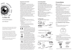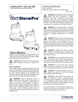
1
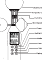
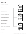
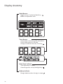
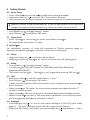
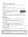
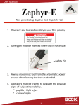
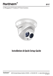
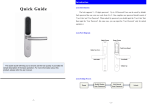
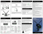
(2013.01) Table of Content 1 Introduction ........................................................................................................... 1 2 Package .................................................................................................................. 1 3 Getting Started ....................................................................................................... 2 3.1 Meter Setup ................................................................................................... 2 3.2 Pager Setup .................................................................................................... 2 4 Instruction .............................................................................................................. 2 4.1 Power ........................................................................................................... 2 4.2 Mode ............................................................................................................ 2 4.3 TWL .......................................................................................................... 2 4.4 Backlight ......................................................................................................... 2 4.5 Timer ............................................................................................................ 3 4.6 Paging ........................................................................................................... 3 4.7 Pager ............................................................................................................ 3 4.8 Battery............................................................................................................ 3 5 Data Logging ........................................................................................................... 3 6 Recalibration .......................................................................................................... 4 7 Polypropylene Filter ............................................................................................... 4 8 Example for a Construction Site ............................................................................. 4 9 Trouble Shooting .................................................................................................... 5 10 Specification ........................................................................................................... 6 11 Certification ............................................................................................................ 6 12 Disclaimer............................................................................................................... 6 13 Acronym ................................................................................................................. 6 Caution TWL-1S is an environmental meter and should only be used as a reference. Good judgment and care are required when making any decisions about safety and health. Your TWL-1S Heat Stress Detector is designed to provide accurate measurement provided that you follow the instruction described in this manual. Any improper uses might cause measurement error or damage to the device. Prior to any measurement: Make sure your TWL-1S is in good condition and within factory calibration. Allow TWL-1S to acclimatize to the environment for 10 min if any significant changes in temperature and humidity occur (e.g. when moving TWL-1S from indoors to outdoors). i ii green 0 - 80 oC w/ resolution 0.1 oC 0 - 50 oC w/ resolution 0.1 oC 5-95% w/ resolution 0.1% TWL≥140 yellow 0.5 - 10 m/s w/ resolution 0.1 m/s Long press to turn power on/off Turn on colorful backlight 115≤TWL<140 red Toggle among 7 modes Long press to turn the timer on/off Calculate TWL * Emit radio signal to pagers TWL<115 *TWL value is based on 120 sec average values of dry bulb, globe bulb, humidity and wind speed. Display Anatomy Mode Banner Toggle among 7 modes by Mode key Mode correspondent units Timer Banner Count down 2 min during TWL calculation Count down based on risk level Change countdown timer by Timer key Work Zone Indicator TWL dependent risk level Colorful signal for risk by Backlight key Battery Indicator Change batteries when the sign is empty iv 1 Introduction Heat illness can be vital. However, with proper precautions, it can be avoided. Thermal Work Limit (TWL) is a heat index calculated from environmental parameters, including dry bulb temperature, wet bulb temperature, globe bulb temperature and wind speed and accommodates for clothing factors as well as human physiological status to estimate a safe maximum continuous suitable metabolic rate. It is designed primarily for self-paced workers who are well hydrated and acclimatized in the working condition. Table 1: Thermal Work Limit (TWL) zones and management intervention. 2 TWL (W/m ) Backlight TWL ≥ 140 Green 115 ≤ TWL < 140 Yellow TWL < 115 Red *safe for all continuous self-paced work Work Time − − min* − − min* 20 min Risk Level Low Risk Medium Risk High Risk TWL-1S Heat Stress Detector offers a compactly designed hardware with deliberate software and user-friendly interface. ˙ TWL dependent backlight informs users the risk level. ˙ Work timer reminds users the work/rest schedule, and actively notifies the remote pager when it counts down to zero. 2 Package ˙ ˙ ˙ ˙ TWL-1S Heat Stress Detector x1 User manual x1 Tripod x1 Pager x1 ˙ ˙ ˙ ˙ Certificate of Conformity x1 Data logger USB cable x1 AAA battery x4 AA battery x1 1 3 Getting Started 3.1 Meter Setup ˙ Insert 4 AAA ba eries into the ba ery holder with proper orienta on. ˙ Long press Power key ( ) to turn on TWL-1S Heat Stress Detector. ˙ Place the meter on a tripod, preferably 1 m above the ground, for proper placement. Expose the meter to the environment for 10 min for equilibrium for any significant changes in temperature and humidity (e.g. indoor to outdoor and vice versa). ˙ ˙ Press Mode key ( ) to toggle among 7 modes. Press TWL key ( ) to calculate a TWL value. 3.2 Pager Setup Insert 1 AA ba ery into the ba ery holder with proper orienta on. ˙ The pager beeps once when it is ready. ˙ 4 Instruc on For explanatory purpose, all icons are presented in Display Anatomy (page iv). However, during daily opera on, only part of these icons is displayed. 4.1 Power ˙ Long press Power key ( ) to turn on or off the device. ˙ When le without any opera on for 15 min, the device turns off automa cally. 4.2 Mode ˙ Press Mode key ( ) to toggle among 7 modes. ˙ It shows real me value for 6 modes (Dry Bulb/Wet Bulb/Globe Bulb/Wind Speed/Humidity/WBGT). ˙ TWL value is not real me. Calcula on is only triggered by pressing TWL key ( ). 4.3 TWL 2 ˙ Before any calcula on, the TWL mode shows ---.- w/m . ˙ Press TWL key ( ) to calculate a TWL value. ˙ It takes 2 min to compute a TWL value because 2-min average is more representa ve than a snapshot. st ˙ When calcula ng a TWL value, the screen shows average wind speed from the 1 second to current moment. ˙ When calcula ng, TWL icon blinks and a countdown mer shows the me remains. ˙ When the calcula on is done, a TWL value and correspondent risk icon shows alone with the suggested work me as indicated in Table 1. 4.4 Backlight ˙ Press Backlight key ( ) t o turn on the colorful backlight of the LCD (Quick Guide, page iii). The color corresponds with the TWL range and risk (Table 1). ˙ Before any TWL value is calculated, pressing Backlight key ( ) only flashes---.- twice. 2 4.5 Timer ˙ Short pressing Timer key ( ) sets the mer. ˙ Long pressing Timer key ( ) starts/ends the mer. ˙ This key only works in High Risk (Red) zone as green and yellow zones do not have work me limits. 4.6 Paging ˙ Press Paging key ( ) to call the remote pagers. ˙ Paging signal covers 200 meters on average, but the range may vary with topology. 4.7 Pager When triggered by TWL-1S, the pager beeps and vibrates. ˙ Press the side bu on (right figure, dashed circle) to stop. ˙ Both red zone and the expira on of work mer trigger the pager 3 mes with 1min interval. ˙ 4.8 Ba ery ˙ Alkaline ba eries can sustain more than 120 hours when operated con nuously. ˙ Dry ba eries and rechargeable ba eries are also applicable but with shorter life me. ˙ Download data when the ba ery bar is empty ( ), otherwise some data might be lost. 5 Data Logging Step1: Configura on ˙ Download so ware (TWLIT) from Scarlet website (www.scarlet.com.tw) and install the so ware on a PC/laptop. ˙ Turn on TWL-1S detector and connect TWL-1S to the PC/laptop by a USB cable. ˙ Launch the so ware, and set sampling rate (minimum 10 min). ˙ Disconnect the meter from the computer, and TWL-1s is ready for data logging. Step2: Data logging ˙ Long press Mode key ( ) to turn on data logging mode and the meter displays SUrE. ˙ Press Mode key ( ), if you agree to enter the data logging mode. ˙ Press Timer key ( ), if you do NOT agree to enter the data logging mode. ˙ When the screen shows rEC, the device is collec ng and recording data; Idle means no data are recorded. ˙ Long press Timer key ( ) to quit data logging mode. Step3: Download data ˙ Connect to the computer to download the data via the PC side so ware you installed in the Configura on session. Important: Be sure to download the data before entering next data logging mode; otherwise, the data will be overwri en. Do not leave the meter uncharged for too long; otherwise, the data might be lost. 3 6 Recalibration Calibration drift happens over time. accuracy of the measurement. Regular recalibration is necessary to ensure the Humidity sensors can be recalibrated using the RH calibration kit which includes saturated salt solutions and two sealed containers. We suggest that you have the humidity sensor calibrated every 6 months. Please contact the sales representatives for RH calibration kit, instruction and services. Temperature sensors (dry air and globe bulb) typically do not require recalibration because the calibration drift is negligible during the product lifetime. Wind speed is calibrated against an intermediary standard calibrated under MEASNET cup anemometer calibration procedure before it leaves the factory. However, we recommend that you have the anemometer checked every 6 month. Please contact the sales representatives for wind speed test and bearing replacement. 7 Polypropylene Filter A polypropylene (PP) fiber is applied to protect the temperature and humidity sensors from dust while allowing water vapor (moist humid air) to pass through. It is suggested to replace the PP filter every 2-6 months depending on the usage condition. Please contact the sales representatives if you wish to change the filter. 8 Example for a Construction Site At a construction site, environmental characteristics are significantly different at different locations. For example, direct sunlight and strong wind might occur at a rooftop while ventilation is limited at a basement. It is suggested to deploy TWL-1S Heat Stress Detectors at different spots to reflect actual situation. Once the TWL-1S Heat Stress Detector is turned on and set up per the instruction mentioned in Section, the meter is ready for measuring the environmental parameters and computing a TWL value. Users can operate TWL-1S with the function keys described in Section 4. Based on the calculated TWL value, the TWL-1S Heat Stress Detector automatically sets up the work timer as suggested in Table 1. If the TWL value is in the Red Zone, TWL-1S will automatically send a warning signal to notify a supervisor through a pager 3 times with 1 min interval. The supervisor can set and start the work timer. When the timer counts down to zero, the pager beeps and vibrates, notifying the supervisor to announce an intermission. Once the intermission is due, the supervisor can turn on the TWL-1S again and press TWL key ( ) to calculate a new TWL value. 4 9 Trouble Shooting First, ensure the batteries are properly inserted. If any error code shows on the LCD, please check Table 2 for solutions Table 2: Error codes and solutions Error code Defect Solution DRY (Dry Bulb Temperature) E02 Measured air temp. is lower than specified Leave the meter in regular air temp. for 30 min. range. E03 Measured air temp. is higher than specified Leave the meter in regular air temp. for 30 min.. range. E31 Circuit AD defect Sent back to repair GLB (Globe Bulb Temperature) E02 Measured temp. is lower than specified range Leave the meter in regular air temp. for 30 min. E03 Measured temp. is higher than specified range Leave the meter in regular air temp. for 30 min. E31 Circuit AD defect Sent back to repair HUM (Humidity) E04 Temp. error causes this defect Refer temp. error code to fix E11 Humidity calibration error Re-calibration correctly. E33 Humidity circuit error Sent back to repair. WET (Wet Bulb Temperature) E02 WET is lower than specified range Leave the meter in regular air temp. for 30 min. E03 WET is higher than specified range Leave the meter in regular air temp. for 30 min. E04 Caused by DRY or HUM error Refer temp. and RH error code to fix WND (Wind Speed) E31 Hardware defect Sent back to repair E02 WBGT is lower than specified range Leave the meter in regular air temp. for 30 min. E03 WBGT is higher than specified range Leave the meter in regular air temp. for 30 min. E04 Caused by DRY/GLB/HUM error Refer temp. and RH error code to fix E02 TWL is lower than specified range Leave the meter in regular air temp. for 30 min. E03 TWL is higher than specified range Leave the meter in regular air temp. for 30 min. E04 Caused by DRY/GLB /HUM/WND error Refer temp. and RH error code to fix WBGT TWL 5 10 Specifica on Parameters Range Resolu on Accuracy Globe Bulb 0-80 oC 0.1 oC Indoor: ±1.0 (15-40oC); ± 1.5oC (others) Air Temperature 0-50 oC 0.1 oC ±0.6 oC Humidity 5-95% 0.1% ±3% (25oC; 10-90%RH) Wind Speed 0.5-10 m/s 0.1 m/s Outdoor: ±1.5 (15-40oC); ± 2.0oC (others) Temperature ±5% (others) 11 Cer ±(2% of reading+0.2) m/s ca on The TWL-1S Heat Stress Detector is cer ed by CE mark following the EN 61326-1:2006 Electrical Equipment for Measurement, Control and Laboratory Use. TWL-1S Heat Stress Detector has also received a third party cer ca on for its temperature and humidity sensors from SGS, a globally renowned company for inspec on, verifica on, tes ng and cer ca on. 12 Disclaimer This manual was wri en by Scarlet Tech Co. Ltd. for the use of TWL-1S Heat Stress Detector. The product and its documenta on (including this manual) are provided “as is” and without warranty of any kind, either expressed or implied, including but not limited to the implied warran es of merchantability, fitness for a par cular purpose or non-infringement. In no event shall Scarlet Tech’s total liability to you for all damages, losses and cause of ac on exceed the amount paid for the product and its documenta on. 13 Acronym AD EHS RI-CoP 11.0 HAAD EHS EHSMS LCD TWL Designed by Scarlet Tech Co. Ltd www.scarlet.com.tw 6 Abu Dhabi Environment, Health and Safety Regulatory Instrument Code of Prac ce 11.0-Safety in the Heat Health Authority Abu Dhabi Health, Safety and Environment Environment, Health and Safety Management System Liquid Crystal Display Thermal Work Limit