1
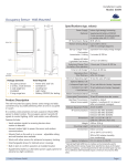
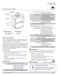
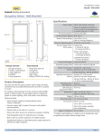
Light Level Sensor – Ceiling Mounted
Specifications (typ. values)
Power Supply
Solar energy harvesting
Measurement Range
0 – 1020 lux
Resolution
4 lux
Typical Accuracy
+- 5% @ full scale, 68°F
Measurement interval
1 minute
Transmission interval
After measurement if change > 50 lux
since last transmission
Heartbeat every 20 ... 30 minutes
(affected at random)
Startup charge time to
Package Contents
Tools Required
5 minutes @ 200 lux for operation
first transmission*
from empty energy store
Sustaining charge*
3 hours per day @ 200 lux
Light Level Sensor
Power drill, 3/16” bit
Time to full charge*
30 hours @200 lux
2 screws, 2 wall
Screwdriver
Operation time in total
80 hours
Light meter
darkness
(after full charge)
Configuration Interface
2 Buttons, 2 LED for device
anchors
Wire bracket
configuration & manual control
Product Description
The ceiling-mounted Light Level Sensor is wireless, powered
by natural light, and uses the solar cell to measure outside
illumination to control open loop dimming systems.
RF Standard
EnOcean 902 MHz
Transmission Range
80 ft. (25 m)
EnOcean Equipment
A5-06-02
Profile
Dimensions
Every minute the light level sensor measures the current
light level via the solar cell.
If the change since last transmission is >50 lux it will
immediately transmit an RF signal including the current
measurement value. Otherwise there will be a heartbeat
(160 mm x 60 mm x 37 mm)
Weight
4.4oz. (125g)
Mounting Position
At the ceiling, close to the ambient
Environment
Indoor use only
32° to 140° F (0° to 60° C)
20% to 85% relative
light source (window)
transmission after 20-30min.
In addition the device provides a light test mode which can
be used to find a suitable position for installation.
6.30” L x 2.36” W x 1.15” D
humidity (non-condensing)
Agency Compliance
FCC, IC, RoHS
* Natural bright light (2000 lux) can be temporarily used to significantly
Product Features:
shorten startup charge times.
Interoperable
Communicates wirelessly with other devices using the
EnOcean wireless standard
Harvests ambient solar energy to power the sensor and
Specified lux values are for typical fluorescent lighting. Lux level
requirements for LED and other types may vary.
For lux reference, OSHA standards require a minimum of 323 lux for
office areas.
wireless communication
Measures light level via the solar cell
Mounts easily on any ceiling material
Enables daylight harvesting in individual fixtures or zones
controlled by LEDR and LEDD or other open loop
dimming systems
© 2015 EnOcean GmbH
V1.0
Page 1
Light Level Sensor – Ceiling Mounted
iii. Insert the first screw loosely and level the
1. Planning
Take a moment to plan for the sensor’s successful operation
and optimal communication with other system components.
Remove the sensor from its packaging and place it under
unde a
bright light to provide the required startup charge.
Choose a proper installation location taking the following
mounting plate.
iv. Insert the second screw
screw and then hand-tighten
hand
the first screw.
B. Mount Using the Wire Bracket
i. Remove the ceiling tile where you want to
mount the sensor.
points into account:
The
T sensor should be located at the ceiling, close to a
window, or directly at the upper end of the interior
window sidewall
The
T chosen location should provide natural light only;
only
the sensor solar cell should not measure artificial light
The sensor should be mounted such that the solar cell
points towards the window so that it measures
measure the
amount of incoming daylight light only.
Use light test mode to see if the sensor properly
measured daylight only.. Light test mode blink rate
should not change if artificial lights are switched on and
off.
In addition, during dusk or dawn use a light meter at the
intended location and switch light on and off. Only small
changes of the reported illumination should be seen
seen.
Consider the construction materials (such as metal) in the
space and obstacles that may interfere with RF signals
ii. Place the mounting plate squarely on the ceiling tile
and use the wire to mark two points for the holes.
iii. Punch two small
small holes through the ceiling tile at
the marked points.
iv. Insert the wire bracket through the
two holes in the mounting plate.
Make sure the ends are roughly
oughly even.
v. Feed the wires through the
holes in the ceiling tile.
vi. On the front of the ceiling tile,
flatten the wire bracket so it is
snug
nug against the mounting plate.
vii. On the back of the ceiling tile, twist
the wires together to hold the
mounting plate securely.
2. Installing
The light level sensor can be mounted on most surfaces with
the provided screws, or mounted on dropped ceilings, using
viii. Replace the ceiling tile.
4. Attach the sensor to the
the provided wire bracket.
mounting plate.
NOTE: It is often easier to link the sensor
sensor before it is
With the 2-button
2 button interface
interface
mounted. Refer to the “Linking” section.
mounted.
facing you, slide the sensor
1. Decide where you want to install the light level sensor.
The solar cell must point towards the window in order to
measure outside illumination
2. Remove the mounting plate from the sensor.
to the left on the mounting
plate until it snaps into
place.
5. Confirm the sensor is properly positioned to measure
outside illumination and has sufficient light to operate.
3. Determine which of the two installation methods is most
appropriate:
A. Screw Mounting Plate to the Mounting Surface
i. Hold the mounting
mounting plate in place and use a pencil to
lightly mark two small
dots for the screw drill
Linking is the process by which different devices are
configured to work with each other in a system. Sometimes
this process is also called Teach
Teach-in
in or Learn-in.
Learn
Specifically for the Light Level Sensor, linking is the process
points.
ii. Drill two holes with a
3/16” drill bit and insert
the wall anchors.
© 2015 EnOcean GmbH
3. Linking
V1.0
by which it identifies itself to an
another
other device that is capable
of receiving
rece
processing its sensor data (e.g.
e.g. an LED
Controller,
Controller a Central
entral Controller or a Gateway).
Gateway
Page 2
Light Level Sensor – Ceiling Mounted
Note that the Light Level Sensor cannot be linked to devices
such as sensors or switches that cannot receive or process its
input data.
Light Test
Before starting light test, ensure the sensor’s energy storage
is fully charged by placing it under bright light (2000 lux)
lux for
1.5 hours.
Linking or unlinking the Light Level Sensor
Use the light test to measure real
real-time
time light levels and
To link the Light Level Sensor with a suitable device, this
is
confirm whether the light level sensor has sufficient natural
device must be powered, within wireless range of the Light
light,
light, is not influenced by artificial lighting and whether the
Level Sensor and set to linking or unlinking mode to receive
light level is within its measurement range.
specific link messages.
messages
1. Hold up or temporary mount the sensor to the intended
Once these conditions are met, the Light Level Sensor is
triggered to send a link radio telegram.
telegram
mounting position.
position
2. Press and hold the Test button for 5 seconds.
The other device receives this link radio telegram and
••> Red & green LEDs will blink to confirm light test is
identifies the sensor ID and sensor type based on the
active.
information presented therein.
therein
3. Watch the LED blink rate to determine the light strength.
The other device then stores these parameters permanently
0 blink: <50 lux
so that it can automatically accept and process future
1 blinks:
blinks 50-250
250 lux
telegrams originating from the Light Level Sensor.
2 blinks: 251-500
251 500 lux
This relationship between the Light Level Sensor and the
3 blinks: 501-750
501 750 lux
device it is linked to can be terminated by unlinking
unlinking the
4 blinks: 751-1000
751 1000 lux
Light Level Sensor from the other device.
device
5 blinks: >1000 lux
4. This test mode will be active for 3 minutes. It can be exit
e
Link / unlink procedure
1. Set the external device (e.g.
e.g. controller or gateway) to
at any time by pressing the Link button.
4. Troubleshooting
Link or Unlink mode (refer to that device’s installation
guide).
Problem
2. Shortly click
click the Link button
on the side of the sensor
Solution Checklist
Sensor does not generate
a wireless message
message
once.
3. The external device will
receive this link/unlink radio telegram and link or unlink
Verify the solar cell is charged
properly
This sends a link/unlink radio
telegram.
Press Test button to transmit radio
Linked device does not
respond to wireless
messages
Check position using light test
Force radio message by pressing Test
button
the Light Level Sensor accordingly.
accordingly
Check for environment or range issues
Verify the device is linked
Check the transceiver connection and
the wiring for errors
NOTE: The button interface on the sensor is used for linking
Check if appropriate devices are
linked according to good system
and testing only.
planning
Refer
er to the “Linking” section of the transceiver /
controller installation guides to complete the linking &
Contains: :
FCC: SZV-STM300U
STM300U
IC: 5713A-STM300U
STM300U
setup process.
This device complies with part 15 of the FCC rules and Industry Canada ICES-003.
ICES
Operation is subject to the following two conditions: (1) This device may not cause harmful
interference, and (2) this device must accept any interference received, including interference
interference
that may cause undesired operation.
IMPORTANT! Any changes or modifications not expressly approved by the party responsible for
compliance could void the user’s authority to operate this equipment.
© 2015 EnOcean GmbH
V1.0
Page 3