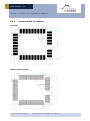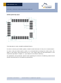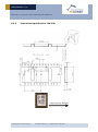
1
USER MANUAL V1.0 TCM 330 / TCM 330U LED CONTROLLER MODULE TCM 330 / TCM 330U LED Controller Module September 1st, 2015 Observe precautions! Electrostatic sensitive devices! Patent protected: WO98/36395, DE 100 25 561, DE 101 50 128, WO 2004/051591, DE 103 01 678 A1, DE 10309334, WO 04/109236, WO 05/096482, WO 02/095707, US 6,747,573, US 7,019,241 © 2015 EnOcean | www.enocean.com TCM 330 User Manual | v1.0 | September 2015 | Page 1/62 USER MANUAL V1.0 TCM 330 / TCM 330U LED CONTROLLER MODULE REVISION HISTORY The following major modifications and improvements have been made to this document: Version 1.00 Author MKA Date Major Changes 01.09.2015 Initial Release Published by EnOcean GmbH, Kolpingring 18a, 82041 Oberhaching, Germany www.enocean.com, [email protected], phone +49 (89) 6734 6890 © EnOcean GmbH, All Rights Reserved Important! This information describes the type of component and shall not be considered as assured characteristics. No responsibility is assumed for possible omissions or inaccuracies. Circuitry and specifications are subject to change without notice. For the latest product specifications, refer to the EnOcean website: http://www.enocean.com. As far as patents or other rights of third parties are concerned, liability is only assumed for modules, not for the described applications, processes and circuits. EnOcean does not assume responsibility for use of modules described and limits its liability to the replacement of modules determined to be defective due to workmanship. Devices or systems containing RF components must meet the essential requirements of the local legal authorities. The modules must not be used in any relation with equipment that supports, directly or indirectly, human health or life or with applications that can result in danger for people, animals or real value. Components of the modules are considered and should be disposed of as hazardous waste. Local government regulations are to be observed. Packing: Please use the recycling operators known to you. © 2015 EnOcean | www.enocean.com TCM 330 User Manual | v1.0 | September 2015 | Page 2/62 USER MANUAL V1.0 TCM 330 / TCM 330U LED CONTROLLER MODULE TABLE OF CONTENT 1 MODULE VARIANTS AND RELATED DOCUMENTS ............................................... 5 2 GENERAL DESCRIPTION ................................................................................. 6 2.1 Basic functionality ......................................................................................... 6 2.2 Technical data TCM 330 / TCM 330U ................................................................ 7 2.3 Physical dimensions TCM 330 / TCM 330U ........................................................ 8 2.4 Environmental conditions ............................................................................... 8 2.5 Ordering information ..................................................................................... 8 3 HARDWARE DESIGN DESCRIPTION ................................................................. 9 3.1 Pin out ......................................................................................................... 9 3.2 Pin description ............................................................................................ 10 3.3 Absolute maximum ratings (non-operating) .................................................... 11 3.4 Maximum ratings (operating) ........................................................................ 11 3.5 System design ............................................................................................ 12 3.5.1 Power supply....................................................................................... 12 3.5.2 0–10V output driver ............................................................................. 13 3.5.3 Relay output ....................................................................................... 14 3.5.4 Zero cross detection ............................................................................. 15 3.5.5 EEPROM ............................................................................................. 16 3.5.6 Antenna ............................................................................................. 17 3.5.6.1 Overview ......................................................................................... 17 3.5.6.2 Whip antenna ................................................................................... 18 3.5.6.3 Helix antenna ................................................................................... 18 3.5.6.4 Chip antenna (Mitsubishi Material, Type AM11DG-ST01) ........................ 19 3.5.7 Local interface ..................................................................................... 20 3.5.7.1 Pushbutton interface ......................................................................... 20 3.5.7.2 LED interface .................................................................................... 20 3.5.8 Programming and configuration interface ................................................ 21 3.5.8.1 Reset and programming input protection ............................................. 22 FUNCTIONAL INFORMATION ......................................................................... 23 4 4.1 General description...................................................................................... 23 4.2 System components .................................................................................... 23 4.3 LED zone controller...................................................................................... 24 4.3.1 PWM output functionality ...................................................................... 25 4.3.2 Status message functionality ................................................................. 25 4.3.3 Repeater functionality .......................................................................... 26 4.4 Wireless switches ........................................................................................ 27 4.4.1 Functional behaviour of wireless switches ............................................... 28 4.5 Wireless occupancy sensors .......................................................................... 29 4.5.1 Functional behaviour of wireless occupancy sensors ................................. 30 4.5.2 Functionality depending on system configuration ..................................... 31 4.5.2.1 Occupancy sensor in stand-alone mode ............................................... 31 4.5.2.2 Occupancy sensor and switches .......................................................... 32 4.6 Wireless light level sensors ........................................................................... 33 © 2015 EnOcean | www.enocean.com TCM 330 User Manual | v1.0 | September 2015 | Page 3/62 USER MANUAL V1.0 TCM 330 / TCM 330U LED CONTROLLER MODULE 4.6.1 Functional behaviour of wireless light level sensors .................................. 34 4.6.1.1 Five point dimming ........................................................................... 35 4.6.1.1.1 Dimming curve adjustment ................................................................ 36 4.6.1.2 Two level dimming ............................................................................ 37 4.6.2 Functionality depending on system configuration ..................................... 38 4.6.2.1 Light Level Sensor in Stand-alone Mode ............................................... 38 4.6.2.2 Light Level Sensor and Switches ......................................................... 39 4.6.2.3 Light Level Sensor and Occupancy Sensors .......................................... 40 4.6.2.4 Light Level Sensor with Occupancy Sensors and Wireless Switches ......... 41 4.7 Central controllers ....................................................................................... 42 4.7.1 Functional behaviour of central controllers .............................................. 42 4.8 Demand response controllers ........................................................................ 42 4.8.1 Functional behaviour of central controllers .............................................. 42 5 SYSTEM CONFIGURATION ............................................................................ 43 5.1 Local configuration interface ......................................................................... 43 5.1.1 Linking ............................................................................................... 43 5.1.2 Device reset ........................................................................................ 43 5.1.3 Setting the minimum output voltage ...................................................... 44 5.1.4 Linking ............................................................................................... 44 5.1.4.1 Linking to transmitters (transmit-only) ................................................ 45 5.1.4.2 Linking to transceivers (transmit & receive) ......................................... 46 5.2 Factory-configurable parameters ................................................................... 47 5.3 6 Remote commissioning ................................................................................ 48 5.3.1 Navigan™ Wireless Commissioner NWC 300U .......................................... 48 5.3.2 Configurable Parameters....................................................................... 49 APPLICATION INFORMATION ........................................................................ 51 6.1 Transmission range ..................................................................................... 51 6.2 Recommendations for laying a whip antenna .................................................. 52 6.3 Layout recommendations ............................................................................. 53 6.3.1 Recommended foot pattern ................................................................... 54 6.3.2 Soldering information ........................................................................... 56 6.3.3 Tape & Reel specification TCM 330 ......................................................... 57 REGULATORY INFORMATION......................................................................... 58 7 7.1 FCC (United States) Certification ................................................................... 58 7.1.1 FCC Regulatory Statements .................................................................. 60 7.2 IC (Industry Canada) Certification ................................................................. 61 7.2.1 Industry Canada Regulatory Statements ................................................. 62 © 2015 EnOcean | www.enocean.com TCM 330 User Manual | v1.0 | September 2015 | Page 4/62 USER MANUAL V1.0 TCM 330 / TCM 330U LED CONTROLLER MODULE 1 MODULE VARIANTS AND RELATED DOCUMENTS This document describes operation of TCM 330 modules available in variations for following frequencies: TCM 330: 868.300 MHz TCM 330U: 902.875 MHz In side this manual the terms TCM 330 is used to describe both TCM 330 and TCM 330U. For system development we recommend following our application notes, in particular: AN101: Power Supply Layout – Layout considerations for Line-Power AN102: Antenna Basics – Basic Antenna Design Considerations for EnOcean based Products © 2015 EnOcean | www.enocean.com TCM 330 User Manual | v1.0 | September 2015 | Page 5/62 USER MANUAL V1.0 TCM 330 / TCM 330U LED CONTROLLER MODULE 2 2.1 GENERAL DESCRIPTION Basic functionality The LED Controller TCM 330 enables implementation of LED Zone Controllers with or without relay functionality. Such controllers use wireless technology to communicate with other self-powered EnOcean based products to provide simple yet powerful solutions for dimming control of LED lighting. TCM 330 can control the dim level of connected LED light sources based on input from the following devices: Wireless Switches Occupancy Sensors Light Level Sensor Central Controller Demand Response Controller It enables advance lighting control compliant with California Title 24 daylight harvesting scenarios. TCM 330 enables both simple configuration via a local 2 button interface and advanced over-the-air parameterization using the EnOcean Remote Commissioning standard and the Navigan NWC 300 installation tool. Built-in operating modes Switch ON / OFF and Dim UP / DOWN based on input from wireless switches Occupancy-controlled lighting based on input from wireless occupancy sensors Daylight-controlled lighting based on input from a Light Level Sensor Central control based on input from a gateway or controller Demand response based on input from a demand response controller © 2015 EnOcean | www.enocean.com TCM 330 User Manual | v1.0 | September 2015 | Page 6/62 USER MANUAL V1.0 TCM 330 / TCM 330U LED CONTROLLER MODULE 2.2 Technical data TCM 330 / TCM 330U Antenna Frequency Radio standard (Modulation) Data rate Receiver sensitivity (typ. at 25 °C) 2) Conducted output power @50 Ω (typ.) Power supply Current Consumption (typ.) Start-up time Control outputs User interface Supported EEPs whip or 50 Ω antenna mountable 868.300 MHz / 902.875MHz ASK 1) / FSK 2) 125 kbps typ. –96 dBm / -98 dBm 2) +5.7 dBm / +1 dBm 3.0 V– 3.3V Receive mode: 33 mA Transmit mode: 24 mA <500 ms Relay control and PWM 2 digital inputs (LRN, DIM) 2 digital outputs for LEDs Occupancy sensors A5-07-01, A5-07-02, A5-07-03 Light sensors A5-06-02, A5-06-03 Rocker switch F6-02-02 Central controller A5-38-08 Demand response A5-37-01 Status message D2-40-00 -25°C to +85°C (-10°F … 180°F) 22 mm x 19 mm x3 mm (0.87” x 0.75” x 0.12”) 1.9 g R&TTE / FCC, IC Operating temperature Dimensions of PCB Weight Radio Regulations 1) according to ISO/IEC 14543-3-10 2) according to ISO/IEC 14543-3-11 3) @ 0.1% telegram error rate (based on 3 transmitted sub-telegrams) © 2015 EnOcean | www.enocean.com TCM 330 User Manual | v1.0 | September 2015 | Page 7/62 USER MANUAL V1.0 TCM 330 / TCM 330U LED CONTROLLER MODULE 2.3 Physical dimensions TCM 330 / TCM 330U Unless otherwise specified, dimensions are in mm. all Tolerances: PCB outline dimensions: ±0.7 mm All other tolerances: ±0.1 mm TCM 330 / TCM 330U (pads on bottom side of PCB!) PCB dimensions 22 x 19 x 3.1 mm Weight 2.4 1.9 g Environmental conditions Operating temperature -25 °C … +85 °C Storage temperature -40 °C … +85 °C Storage temperature in tape & reel package -20 °C … +50 °C Humidity 2.5 0% … 93% r.H., non-condensing Ordering information Type TCM 330 TCM 330U Ordering Code S3003-K330 S3053-K330 © 2015 EnOcean | www.enocean.com Frequency 868.300 MHz 902.875 MHz TCM 330 User Manual | v1.0 | September 2015 | Page 8/62 USER MANUAL V1.0 TCM 330 / TCM 330U LED CONTROLLER MODULE 3 3.1 HARDWARE DESIGN DESCRIPTION Pin out The figure above shows the pin out of the TCM 330 / TCM 330U LED Controller module. © 2015 EnOcean | www.enocean.com TCM 330 User Manual | v1.0 | September 2015 | Page 9/62 USER MANUAL V1.0 TCM 330 / TCM 330U LED CONTROLLER MODULE 3.2 Pin description HW Symbol TCM 330 pin # GND 1, 5, 7, 17, 24, 26, 28, 31 VDD 2 RVDD 8 DVDD 25 IOVDD 23 RESET 27 Function Comments Ground connection Must be connected to GND 2.6 V – 3.3 V Max. ripple: see 3.4 Unused, leave open Unused, leave open Connect to VDD Connect on board to 10 kΩ pull-down parallel to 10nF capacitor Output for whip antenna 50 Ohm output for external antenna Connect to external EEPROM (Microchip 24AA08, see 3.5.5) RF_WHIP RF_50 ADIO0 ADIO5 ADIO4 ADIO3 4 6 9 14 13 12 Supply voltage Internal regulator Internal regulator VDD for IO Functions Reset input (also Programming I/F) RF output RF output I2C - SCL ISC - SCA PWM output Primary Relay Control ADIO2 11 Relay Overdrive ADIO1 10 Zero Cross Detect WXIDIO WXODIO WSDADIO2 RSDADIO3 n.c. 29 30 21 22 3, 15, 32,33, 34 Programming Interface VDD 2 DIM Button Input LRN Button Input RED LED GREEN LED Not connected GND Supply voltage grammer Ground RESET Common Ground 27 PROG_EN 18 RSDADIO3 WSDADIO2 SCLKDIO1 SCSEDIO0 ADIO7 22 21 20 19 16 © 2015 EnOcean | www.enocean.com Connect to 0-10V driver stage (see 3.5.2) Connect to Relay if present (see 3.5.3) HIGH if external relay is closed LOW otherwise Connect to Relay if present (see 3.5.3) HIGH for 110 ms during relay closing Connect to zero cross detection (see 3.5.4) Connect to DIM / LRN button if present (see 3.5.7.1) Connect to RED / GREEN LED Maximum current 2 mA (see 3.5.7.2) Do not connect! from pro- Programming I/F Active HIGH Programming I/F HIGH: Programming Mode LOW: Functional Mode Programming I/F Programming interface (If applicable, see 3.5.8) TCM 330 User Manual | v1.0 | September 2015 | Page 10/62 USER MANUAL V1.0 TCM 330 / TCM 330U LED CONTROLLER MODULE 3.3 Symbol VDD IOVDD GND VINA VIND1 VIND2 3.4 Absolute maximum ratings (non-operating) Parameter Supply voltage at VDD Must be same as VDD Ground connection Voltage at every analog input pin Voltage at RESET and every digital input pin except WXIDIO/WXODIO Voltage at WXIDIO / WXODIO input pin (LRN / DIM button) Min Max Units -0.5 3.6 V -0.5 0 -0.5 -0.5 3.6 0 2 3.6 V V V V -0.5 2 V Maximum ratings (operating) Symbol Parameter Min Max Units VDD Supply voltage at VDD 3.0 3.3 V IOVDD Must be same as VDD 3.0 3.3 V GND Ground connection 0 0 V VINA Voltage at every analog input pin 0 2.0 V Voltage at RESET, and every digital input pin except 0 3.3 V VIND1 WXIDIO / WXODIO Voltage at WXIDIO / WXODIO input pin 0 2.0 V VIND2 (LRN / DIM button) VDDR Max. ripple at VDD 50 mVpp © 2015 EnOcean | www.enocean.com TCM 330 User Manual | v1.0 | September 2015 | Page 11/62 USER MANUAL V1.0 TCM 330 / TCM 330U LED CONTROLLER MODULE 3.5 System design In order to ensure reliable operation it is recommended to follow the external circuitry recommendations given in this chapter. The high level system design is shown below. PWM to 0-10V Output Driver 0-10V Output EEPROM Driver Regulator (12V, if needed) Local User Interface DC Input (12V or similar) TCM 330 Regulator (3.3V) TCM 330 Either AC or DC Input AC Input (Line Power) Transformer / Rectifier Relay (Optional) 3.5.1 AC Zero Cross Detection Relay Driver (optional Overdrive) Programming Interface Power supply TCM 330 can be used in two system configurations: DC (typically 12V) supplied system The supply voltage is typically provided by an auxiliary power output of the LED driver. Internal regulation for TCM 330 supply voltage (3.0V … 3.3V) and potentially the 0-10V driver (typically 12V, depending on input voltage and output driver design) is required. AC (line power) supplied system Line power is used as supply voltage. Use of transformer, rectifier, Driver regulator and TCM 330 regulator is required. Line power supply to the LED driver can be controlled by a relay in order to save power when the LED driver is in OFF state. TCM330 requires a single supply voltage between 3.0V and 3.3V. This supply voltage is used both to supply the internal core functions and the IO cells. The ripple should be under 10mVpp for optimal RF performance. Care should be taken to avoid emitted and conducted emissions and attention must be paid to the power supply and a correct layout and shielding to achieve best RF performance. Refer to app note Power Supply Layout [AN101] for recommendations. In noisy environments it is recommended to place a 22 µF ceramic capacitor between VDD and GND close to the module (material: X5R, X7R, min 6.3 V to avoid derating effects). In addition, an HF SMD EMI Suppression Ferrite Bead such as the Würth WE-CBF HF SMD EMI Suppression Ferrite Bead (Würth order number 742863160) can be inserted into the power supply line. © 2015 EnOcean | www.enocean.com TCM 330 User Manual | v1.0 | September 2015 | Page 12/62 USER MANUAL V1.0 TCM 330 / TCM 330U LED CONTROLLER MODULE 3.5.2 0–10V output driver TCM 330 provides a PWM output with a frequency of 80 kHz. The PWM output is configured to be active high, i.e. a duty cycle of 100% will result in the output being permanently set to high. Conversion of the PWM output signal to a 0-10V driver signal is typically done by using a low pass filter followed by a non-inverting amplifier. The gain of the amplifier must be chosen according to the IO voltage of TCM 330 such that 100 % duty cycle at the TCM 330 PWM output will result in 10V output voltage at the driver. The output of the 0-10V driver should be properly ESD protected if it is exposed to user contact. The illustration below shows an example of such 0-10V output driver. Both a minimum and a maximum output voltage level can be configured in TCM 330 by means of setting a minimum and maximum duty cycle accordingly. This feature prevents flickering at very low output voltage levels and can conserve energy in systems where the maximum available LED brightness is not required. © 2015 EnOcean | www.enocean.com TCM 330 User Manual | v1.0 | September 2015 | Page 13/62 USER MANUAL V1.0 TCM 330 / TCM 330U LED CONTROLLER MODULE 3.5.3 Relay output TCM 330 provides the option to control a relay in order to cut the supply voltage to external components if the LED controller output is set to OFF. The typical application for this functionality is to control the power voltage supply of the LED driver connected to the output of the LED controller. TCM 330 provides two outputs for relay control: Primary Relay Control This output signal is set to active (high) if the output of TCM 330 is ON (output level > 0V); otherwise it is inactive (low). Relay Overdrive This output signal is set to active (high) for a period of 110 ms during the transition from relay OFF to ON state. Use of this signal in a relay driver is optional. The use of both Primary Relay Control and Relay Overdrive signals enables power efficient relay driver designs. In such designs high current is provided during the mechanical transition from relay OFF to ON state based on the Relay Overdrive signal. Once the relay has reached ON state, a lower current for maintaining ON state is provided based on the Primary Relay Control signal. © 2015 EnOcean | www.enocean.com TCM 330 User Manual | v1.0 | September 2015 | Page 14/62 USER MANUAL V1.0 TCM 330 / TCM 330U LED CONTROLLER MODULE 3.5.4 Zero cross detection TCM 330 provides the option to synchronize relay switching with the zero crossing of the sinusoidal input line voltage in order to minimize electrical stress on the relay contacts. TCM 330 relies on the application circuit for providing a digital input signal (falling edge) which identifies the moment of zero crossing. TCM 330 then measures the period between consecutive zero crossings in order to determine the AC line frequency (60 Hz or 50 Hz) and calculates the timing of subsequent zero crossings based on that. TCM 330 allows specifying timing offsets both for relay close and relay open actions to account for the timing difference between relay control signal change and relay contact state change: Relay Switch ON Time This parameter specifies the timing offset for the case of the relay closing (when contact is made). It defines how much time in advance of the zero crossing the relay driver output must be set to active. The default value is 4.0 ms, it can be adjusted in 50us steps. Relay Switch OFF Time This parameter specifies the timing offset for the case of the relay opening (when contact is lost). It defines how much time in advance of the zero crossing the relay driver output must be set to inactive. The default value is 1.5 ms, it can be adjusted in 50us steps. This feature is especially important for the case of relay close (make contact) where the relay contacts have to mechanically travel a certain distance between their open state and the point where contact is made. The operating time required for this mechanical travel is typically several milliseconds and must therefore be taken into consideration. The release time (from relay input going to inactive until contact is opened) is typically less but should be considered as well. © 2015 EnOcean | www.enocean.com TCM 330 User Manual | v1.0 | September 2015 | Page 15/62 USER MANUAL V1.0 TCM 330 / TCM 330U LED CONTROLLER MODULE 3.5.5 EEPROM TCM330 relies on an external EEPROM for storage of frequently changing parameters such as configuration and status information as well as link tables. The recommended EEPROM is Microchip 24AA08. An I2C interface to the EEPROM is implemented in TCM 330 providing SCL and SDA interface signals. External 1k pull up resistors to VDD (positive supply voltage) are required for correct operation. The illustration below shows the recommended connection between TCM 330 and the external EEPROM. © 2015 EnOcean | www.enocean.com TCM 330 User Manual | v1.0 | September 2015 | Page 16/62 USER MANUAL V1.0 TCM 330 / TCM 330U LED CONTROLLER MODULE 3.5.6 Antenna 3.5.6.1 Overview Several antenna types have been investigated by EnOcean. Please refer to our application notes AN102, and AN105 which give an overview on our recommendations. TCM330 (868.3 MHz) has been approved with whip antenna. Modules based on TCM 330 that are used in Europe do not need additional radio approval if the external antenna fulfils the following requirements: Frequency band 868.300 ISM Antenna type Passive Mandatory for radio approval Impedance ~50 Ohm Mandatory for radio approval Maximum gain ≤ 0 dBd MHz Antenna must be suited for this band Mandatory for radio approval In addition it is important to fulfill the following requirements in order to achieve compatibility with other EnOcean products and to ensure excellent EMI robustness: VSWR ≤ 3:1 Important for compatibility with EnOcean protocol Return Loss > 6 dB Important for compatibility with EnOcean protocol Bandwidth ≤ 20 MHz Important if 10 V/m EMI robustness required for device TCM330U (902.875 MHz) is designed for use with the following antenna types: EnOcean-defined whip antenna EnOcean-defined helix antenna Chip antenna Mitsubishi Material, Type AM11DG-ST01 TCM 330U is FCC / IC pre-approved (limited modular approval) for these antennas. Please contact EnOcean for details. Note that a full FCC / IC approval is needed if TCM 330U modules are used in US / Canada with antennas other than these specified antennas. © 2015 EnOcean | www.enocean.com TCM 330 User Manual | v1.0 | September 2015 | Page 17/62 USER MANUAL V1.0 TCM 330 / TCM 330U LED CONTROLLER MODULE 3.5.6.2 Whip antenna The whip antenna parameters are shown below. 902.875 MHz Antenna: 64 mm wire, connect to RF_WHIP Minimum GND plane: 50 mm x 50 mm Minimum distance space: 10 mm 868.3 MHz Antenna: 86 mm wire, connect to RF_WHIP Minimum GND plane: 38 mm x 18 mm Minimum distance space: 10 mm 3.5.6.3 Helix antenna 902.875 MHz Design according to drawing below. Minimum GND plane: 35 mm x 30 mm Minimum distance space: 10 mm © 2015 EnOcean | www.enocean.com TCM 330 User Manual | v1.0 | September 2015 | Page 18/62 USER MANUAL V1.0 TCM 330 / TCM 330U LED CONTROLLER MODULE 3.5.6.4 Chip antenna (Mitsubishi Material, Type AM11DG-ST01) 902.875 MHz Please refer to PCB drawing below for design instructions. The following conditions apply for use of the EnOcean FCC / IC limited modular approval: Dimensions may not be shortened Matching circuit is part of the limited modular approval and may not be changed Minimum top and bottom side ground plane required as shown below Connect ground planes using multiple via as shown Connect matching circuit to RF_50 Use High Q wire wound inductors, e.g. 0603 Murata LQW18A series. Use the following matching circuit values: L1 = 3.9 nH; L2 = 33 nH, L3 = 12 nH. Please contact EnOcean if you intend to use this design with EnOcean FCC / IC limited modular approval. For additional information or chip antenna quotes, please refer to Mitsubishi Materials website at www.mmea.com or email to [email protected]. © 2015 EnOcean | www.enocean.com TCM 330 User Manual | v1.0 | September 2015 | Page 19/62 USER MANUAL V1.0 TCM 330 / TCM 330U LED CONTROLLER MODULE 3.5.7 Local interface TCM 330 provides the option to use a local interface for simple configuration and status display tasks. This interface consists of two pushbuttons (called LRN and DIM) and two LED (red and green, either as two separate LED or as an integrated bi-color solution). 3.5.7.1 Pushbutton interface The two pushbuttons have to be connected as follows: LRN button to WXODIO input of TCM 330 (pin 30) DIM button to WXIDIO input of TCM 330 (pin 29) Both inputs are active low. Proper debouncing circuitry should be included. 3.5.7.2 LED interface The two LED’s have to be connected as follows: Green LED to RSDADIO3 output of TCM 330 (pin 22) Red LED to WSDADIO2 output of TCM 330 (pin 21) Both outputs are active high. Output current should be limited via 560 Ohm series resistors. One possible implementation of the pushbutton and LED interface is shown below. © 2015 EnOcean | www.enocean.com TCM 330 User Manual | v1.0 | September 2015 | Page 20/62 USER MANUAL V1.0 TCM 330 / TCM 330U LED CONTROLLER MODULE 3.5.8 Programming and configuration interface The programming and configuration interface is optional and enables three functions: Configuration of relay switching parameters: Relay Switch On, Relay Switch Off and Relay Overdrive Time Firmware updates An example header with the required programming interface signals and supporting circuitry is shown below. The selected programming interface connector needs to be connected to an EnOcean programmer board such as the EOP350 via a suitable adapter cable. See EnOcean application note AN502 for details. EnOcean can provide a spring-loaded header cable based on 2mm contact spacing for programming. Please contact EnOcean for details. © 2015 EnOcean | www.enocean.com TCM 330 User Manual | v1.0 | September 2015 | Page 21/62 USER MANUAL V1.0 TCM 330 / TCM 330U LED CONTROLLER MODULE 3.5.8.1 Reset and programming input protection In order to ensure reliable operation it is recommended to connect both the reset (RESET) and the programming (PROG_EN) input of the programming interface with a 10 kΩ resistor in parallel with a 10 nF capacitor to ground. This avoids spurious signal detection in very noisy environments and in situations where an external programming header is provided. The suggested circuit is shown below. © 2015 EnOcean | www.enocean.com TCM 330 User Manual | v1.0 | September 2015 | Page 22/62 USER MANUAL V1.0 TCM 330 / TCM 330U LED CONTROLLER MODULE 4 FUNCTIONAL INFORMATION 4.1 General description TCM 330 allows implementation of LED zone controller using wireless technology to communicate with other self-powered EnOcean based products. LED zone controllers based on TCM 330 provide simple solutions for dimming control of LED lighting. They can be wirelessly linked to EnOcean-based motion sensors, rocker switches and a light level sensor. Central control is possible by linking the LED zone controller to a central controller or via a gateway to building automation systems like BACnet. LED zone controller based on TCM 330 can be wirelessly configured over the air using the EnOcean Remote Commissioning standard. Configurable parameters are marked in Italics in the following chapters. 4.2 System components Wireless lighting control systems based on LED zone controllers contain one or several of the following components: LED zone controllers LED zone controllers receive input from linked devices and controls the LED light level using its 0-10V and relay outputs. The LDE zone controller is connected to an LED driver which in turn supplies the LED string of the light source. Wireless switches Wireless switches can be used to send switch on / off and dim up / down commands to the LEDR Wireless occupancy sensors Wireless occupancy sensors can be used to signal presence or absence of persons in their vicinity to the LEDR Wireless light level sensors Wireless light level sensors can be used to report the amount of external light (typically daylight) being present in their vicinity Central controller Central controller can be used to provide a centralized control and user interface to the lighting control system. It can also act as a gateway to a building automation system like BACnet. Demand response controller Demand response controller can instruct LED zone controller based on TCM 330 to temporarily reduce output setting to conserve energy during periods of energy shortage © 2015 EnOcean | www.enocean.com TCM 330 User Manual | v1.0 | September 2015 | Page 23/62 USER MANUAL V1.0 TCM 330 / TCM 330U LED CONTROLLER MODULE 4.3 LED zone controller LED zone controller based on TCM 330 acts as the central receiver and processor of input data (commands or status messages) from linked components. Based on this input data, it determines the appropriate lighting level and sets the output signals connected to the LED Driver accordingly. The LED driver then adjusts LED supply voltage and supply current such that the commanded light level is achieved. The typical system setup for a line powered LED zone controller is shown below. The LED zone controller receives wireless input in the form of EnOcean radio telegrams using its antenna. Power is provided by means of an AC power supply input or alternatively a DC input as described in chapter 3.5.1. LED zone controller controls the LED driver using two signals: Driver control signal (0-10V Output) LED zone controller signals the required dim level to the LED driver using a standard 010V interface where 0V means no illumination (OFF) while 10V means maximum illumination. Driver power supply (Relay Output) – optional feature LED zone controller can control line power supply (120V) to the LED Driver by means of an integrated relay. In such setup, power to the LED driver would be provided only if the light is commanded to be ON. Based on these two signals, the LED driver will then set the right supply voltage and supply current to the LED string in order to achieve the requested illumination level. © 2015 EnOcean | www.enocean.com TCM 330 User Manual | v1.0 | September 2015 | Page 24/62 USER MANUAL V1.0 TCM 330 / TCM 330U LED CONTROLLER MODULE 4.3.1 PWM output functionality The minimum output voltage can be configured using MinVoltageLevel (default 10% = 1.0V) and the maximum output using MaxVoltageLevel (default 100% = 10.0V). Dimming below MinVoltageLevel or above MaxVoltageLevel is not possible. Level and ramp percentage levels given throughout this document refer to the interval between MinVoltageLevel (1%) and MaxVoltageLevel (100%). An output level of 0% equals OFF state. 4.3.2 Status message functionality LED zone controller based on TCM 330 can report their current status at random intervals to a central controller or gateway. This functionality can be used both to enable system status control and to provide status visualization via a user interface. TCM 330 can transmit a status message based on EnOcean Equipment Profile (EEP) D2-40-00 after each change of its output state (event-based messages) or periodically with a random delay after the StatusMessageTimer has elapsed. Status messages can be switched off completely by setting StatusMessageTimer to 0. Setting StatusMessageTimer to 0xFFFF will cause only event-based messages to be sent. The following parameters are reported as part of the status message: Output state (OFF / ON) 0x0: Output state = OFF 0x1: Output state = ON Output dim level 0x00 = 0% 0xC8 = 100% Cause for transmitting the status message 0x0 = Event 0x1 = Heartbeat Occupancy state 0x0 = not occupied (OccAutoOffTimer has timed out) 0x1 = occupied 0x2 = unknown (No occupancy information available) Daylight harvesting mode 0x0: Daylight harvesting not active (no light level sensor is linked) 0x1: Daylight harvesting active (light level sensor is linked) Demand response mode 0x0: Demand response mode is not active 0x1: Demand response mode is active © 2015 EnOcean | www.enocean.com TCM 330 User Manual | v1.0 | September 2015 | Page 25/62 USER MANUAL V1.0 TCM 330 / TCM 330U LED CONTROLLER MODULE 4.3.3 Repeater functionality LED zone controller based on TCM 330 can provide repeater functionality. Repeaters are used to extend radio range as they retransmit received telegrams after a random delay. TCM 330 supports both first level repeating (repeating only original telegrams) and second level repeating (where telegrams from a first level repeater are repeated for a second time). Repeating in general and second level repeating in particular should be used only if required based on careful planning as it significantly increases radio traffic and thereby the likelihood of radio telegram collisions. TCM 330 provides the option for Link-based Repeating where only such telegrams are repeated that originate from devices that TCM 330 is linked to. This Link-based Repeating option is enabled by default and should be disabled only if required. © 2015 EnOcean | www.enocean.com TCM 330 User Manual | v1.0 | September 2015 | Page 26/62 USER MANUAL V1.0 TCM 330 / TCM 330U LED CONTROLLER MODULE 4.4 Wireless switches Energy harvesting wireless switches provide the flexibility and ease of use provided by wireless solutions without the need for maintenance found in battery-operated devices. Energy harvesting wireless switches can be freely positioned anywhere within the radio range of LEDR. Setup is very easy as no wiring is required. Energy harvesting wireless switches can be used in conjunction with LEDR to dim (adjust the illumination level) up and down or to switch the light on (either to maximum or to predefined brightness) and off. Energy harvesting wireless switches can usually be either single rocker or dual rocker designs. The picture below shows an example of each design. Additional product information for these energy harvesting switches can be found here: https://www.enocean.com/en/enocean_modules_902mhz/wireless-switch-esrp-edrp-oem/ LED zone controller based on TCM 330 can accept input from up to 20 wireless switches using EnOcean End Equipment Profile (EEP) F6-02-02. © 2015 EnOcean | www.enocean.com TCM 330 User Manual | v1.0 | September 2015 | Page 27/62 USER MANUAL V1.0 TCM 330 / TCM 330U LED CONTROLLER MODULE 4.4.1 Functional behaviour of wireless switches Wireless switches are used to manually set the desired light level. EnOcean LED zone controllers can receive input from up to 20 wireless switches using EnOcean Equipment Profile F6-02-02. The following actions are supported for wireless switches: Short click (<0.7s) on “I” button Light comes ON and brightens from MinVoltageLevel (default 1.0V) to the most recent dimming value. At first usage or after a reset, the output will be switched to MinVoltageLevel. The rate of brightening is defined by RockerSwitchOnSpeed (default 20% per second). Double click (<0.7s) on “I” button Light is switched ON at MaxVoltageLevel (default 10.0V). The rate of brightening is defined by RockerSwitchOnSpeed (default 20% per second). Short click (<0.7s) or double click (<0.7s) on “0” button The current light level is stored, the light is dimmed down to MinVoltageLevel and then switched OFF. The rate of dimming down is defined by RockerSwitchOffSpeed (default 20% per second). Press and hold “I” button Light is brightened until button is released or MaxVoltageLevel is reached. The rate of brightening is defined by RockerDimUpSpeed (default 20% per second). This function can be disabled by setting RockerDimEnable = 0. If disabled then any press (short / long / single / double) on the “I” button will set the light level to 100 % (MaxVoltageLevel) immediately. Press and hold “0” button Light is dimmed until button is released or MinVoltageLevel is reached. The rate of dimming is defined by RockerDimDownSpeed (default 20% per second). This function can be disabled by setting RockerDimEnable = 0. If disabled then any press (short / long / single / double) on the “0” button will set the light level to 0% (OFF) immediately. Timer-based Auto OFF Light can be switched OFF automatically in absence of an occupancy sensor after timeout of RockerSwitchAutoOffTimer. This feature can be disabled by setting RockerSwitchAutoOffTimer = 0. This feature is automatically disabled if an occupancy sensor is present. In this case, automatic switch OFF of the light will be performed based on the input from the occupancy sensor. © 2015 EnOcean | www.enocean.com TCM 330 User Manual | v1.0 | September 2015 | Page 28/62 USER MANUAL V1.0 TCM 330 / TCM 330U LED CONTROLLER MODULE 4.5 Wireless occupancy sensors Energy harvesting wireless occupancy sensors in conjunction with EnOcean LED zone controllers increase user convenience and help reduce energy cost. This is achieved by automatically switching the lights off and - optionally - also on according to the presence of persons within the detecting range. Implementing occupancy-based light control is specified as part of Title 24 regulation. Energy harvesting occupancy sensors are usually either wall-mounted or ceiling-mounted depending on the specific application needs. The picture below shows an example of each design (wall-mounted on the left, ceiling-mounted on the right). Additional product information for these energy harvesting occupancy sensors can be found here: https://www.enocean.com/en/enocean_modules_902mhz/ceiling-mounted-occupancysensor-eosc-oem/ https://www.enocean.com/en/enocean_modules_902mhz/wall-mounted-occupancysensor-eosw-oem/ Functionality of occupancy sensors is typically such that they immediately report motion if it is detected for the first time after a period without motion. This enables LED zone controllers to immediately switch ON the light upon motion detection. Subsequently, detected motion is reported via periodical status update telegrams (e.g. every 2 minutes). These telegrams will cause the light to remain ON. If no telegram indicating detected motion has been received for a certain period of time (e.g. 15 minutes) then the room is considered unoccupied. Light is switched OFF after such period has elapsed without reported motion. No dedicated “unoccupied” telegram has to be sent. © 2015 EnOcean | www.enocean.com TCM 330 User Manual | v1.0 | September 2015 | Page 29/62 USER MANUAL V1.0 TCM 330 / TCM 330U LED CONTROLLER MODULE 4.5.1 Functional behaviour of wireless occupancy sensors Wireless occupancy sensors are used to switch OFF – and optionally switch ON – the light based on occupancy in a room. EnOcean LED zone controllers can receive input from up to 10 wireless occupancy sensors using EnOcean Equipment Profiles (EEP) A5-07-01, A5-07-02 or A5-07-03. The following actions are supported for wireless occupancy sensors: Occupancy-based Auto OFF If none of the linked wireless occupancy sensors reports motion for a period defined by OccAutoOffTimer (default 15min) then light is set to OccAutoOffLevel (default 0%). This feature can be disabled by setting OccAutoOffTimer to 0. Note that OccAutoOffTimer should not be set to a period shorter than the normal motion reporting interval (typically around 2 minutes) as otherwise the light would be switched OFF even though the room is still occupied. Ramp-down speed is configurable via SensorRampDownSpeed (default 20% per second). Occupancy-based Auto ON If at least one sensor reports motion then light is set to OccAutoOnLevel (default 100%). Ramp-up speed is configurable via SensorRampUpSpeed (default 20% per second). © 2015 EnOcean | www.enocean.com TCM 330 User Manual | v1.0 | September 2015 | Page 30/62 USER MANUAL V1.0 TCM 330 / TCM 330U LED CONTROLLER MODULE 4.5.2 Functionality depending on system configuration Wireless occupancy sensors can be used in two different system configurations: Stand-alone Wireless occupancy sensors can be used without additional input devices such as wireless switches. This can be useful to automatically control lighting in places where light switches are not commonly used or easily available. In combination with wireless switches The more common application is to have both wireless switches and occupancy sensors working together in a system. This is especially useful in meeting rooms or other places where light should be automatically switched OFF if they are unoccupied. 4.5.2.1 Occupancy sensor in stand-alone mode If wireless occupancy sensors are used stand-alone (without switches and light level sensor) then Auto ON functionality is always enabled because there is no other way to switch the light ON. Light is switched ON (Auto ON function) immediately to OccAutoOnLevel (default 100%) in this configuration if motion is reported. OccAutoOnDelay (see below) is not used. Auto OFF functionality is set according to the value defined by OccAutoOffTimer. Light is switched OFF (to OccAutoOffLevel - default 0%) if no motion has been reported for the period defined by OccAutoOffTimer. Setting OccAutoOffTimer to 0 (which disables Auto OFF functionality) should be avoided if only occupancy sensors are linked. © 2015 EnOcean | www.enocean.com TCM 330 User Manual | v1.0 | September 2015 | Page 31/62 USER MANUAL V1.0 TCM 330 / TCM 330U LED CONTROLLER MODULE 4.5.2.2 Occupancy sensor and switches If wireless occupancy sensors are used in conjunction with wireless switches then by default Occupancy Auto OFF functionality is enabled and Auto ON functionality is disabled. I.e. the default behaviour in this setup is that occupancy sensor input will only be used to switch the light OFF in order to conserve energy. Timer-based Auto OFF (as defined by RockerAutoOffTimer) is always disabled if at least one occupancy sensor is linked. Occupancy-based Auto ON function can be enabled by setting OccAutoOn = ON. In this case light is also switched ON automatically if a linked occupancy sensor reports motion. In that case, if the current light level is OFF (0%) and a linked occupancy sensor reports motion then the output light level is set to OccAutoOnLevel. If the current light level is ON (any level > 0%) then the current light level is not changed if a linked occupancy sensor reports motion. If a user has switched the light OFF via linked wireless switch then LED controller can be prevented from switching the light back ON based on input from linked occupancy sensors (if Auto ON functionality is enabled) for a period defined by OccAutoOnDelay (default 15 minutes). In that case input from linked occupancy sensors is discarded during this period. This can be useful in a situation where Auto ON functionality is enabled and the user manually switches the light OFF, e.g. during a presentation. If light has been switched OFF due to Occupancy Auto OFF function then light will be automatically turned back ON at the last state if occupancy is reported within a period set by VacancyGraceTimer period (default 45s) even when Auto ON functionality is disabled. If OccAutoOffLevel is set to a value different from OFF (0%) – e.g. to 10% - then the Auto OFF function of the occupancy sensor will set the light to that level. Light can then be switched fully OFF by single or double click on the “0” button of a linked wireless switch. © 2015 EnOcean | www.enocean.com TCM 330 User Manual | v1.0 | September 2015 | Page 32/62 USER MANUAL V1.0 TCM 330 / TCM 330U LED CONTROLLER MODULE 4.6 Wireless light level sensors Energy harvesting wireless light level sensors in conjunction with LED zone controllers help reduce energy cost by automatically adjusting the light level according to the amount of incoming light (typically daylight). This process of adjusting the required illumination by considering the external light is sometimes referred to as “Daylight Harvesting”. Implementing Daylight Harvesting is specified as part of Title 24 regulation. Energy harvesting light level sensors are usually either ceiling-mounted in close proximity to the window from where incoming light is expected. It is important to set them up such that they only react to incoming (i.e. external) light and not to the internal lighting system. The picture below shows an example of a ceiling-mounted energy harvesting wireless light level sensor. © 2015 EnOcean | www.enocean.com TCM 330 User Manual | v1.0 | September 2015 | Page 33/62 USER MANUAL V1.0 TCM 330 / TCM 330U LED CONTROLLER MODULE 4.6.1 Functional behaviour of wireless light level sensors Wireless level sensors are used to adjust the light level based on available natural light. The fundamental idea is that less artificial lighting is required if sufficient natural light is available. The concept of controlling the light level based on the amount of available natural light is called “daylight harvesting” and enables significant energy savings. This approach is also referred to as “Open Loop Dimming” since it considers only the available natural light for regulation and does not measure the combines (natural + artificial) light level. In contrast, “Closed Loop Dimming” (sometimes also called Constant Light Dimming) measures the total available light (natural and artificial) and tries to keep this level constant. Closed loop dimming is a much more complex approach and relies on the ability to exactly measure the combined light level at the place where it is needed (e.g. office desk) which is not trivial. It can also result in noticeable variations in the light level which is not desirable. Open loop dimming has therefore been chosen for EnOcean LED zone controllers. LED zone controllers receive information about the amount of available natural light from one linked light level sensor using EnOcean Equipment Profiles (EEP) A5-06-02 or A6-0603. For correct operation it is essential that the light level sensor reports only natural light and is influenced as little as possible by artificial light. The light level sensor should therefore be placed at a position facing the window or skylight where it is not or only minimally influenced by light from the fixtures. Two different dimming modes are possible based on light level sensor input: Five point (continuous) dimming In this mode, the user (or installer) can define the relationship between output light level and available artificial light reported by the light level sensor based on a dimming curve with five supporting points. This mode is commonly used for indoor lighting as it enables smooth dimming which is barely noticeable to the user. Two level (ON / OFF) dimming The light level sensor can alternatively be used to activate an automatic switching mode between MaxVoltageLevel and MinVoltageLevel based on light intensity. One typical application is a twilight switch where the light will automatically be turned ON during darkness. The default operation mode is five point dimming. Two level dimming can be enabled by setting DaylightingMode accordingly. Both modes are described in more detail now. © 2015 EnOcean | www.enocean.com TCM 330 User Manual | v1.0 | September 2015 | Page 34/62 USER MANUAL V1.0 TCM 330 / TCM 330U LED CONTROLLER MODULE 4.6.1.1 Five point dimming Five point dimming is implemented based on a continuous user-defined dimming curve which specifies the relationship between reported natural light level and requested output (artificial) light level. The general principle is that more reported natural light (input) should lead to less requested artificial light (output); therefore the dimming curve should be falling. The dimming curve is defined based on five points. Each of these points is defined by the correspondence between a reported natural light level (LEV1 … LEV5) and a requested output light level (OUT1 … OUT5). The dimming curve must be defined monotonous, i.e. LEV1 < LEV2 < LEV3 < LEV4 < LEV5. In most circumstances, the requested output light level will also be monotonous, i.e. OUT1 >= OUT2 >= OUT3 >= OUT4 >= OUT5. This is however not a requirement from a technical point of view. The default dimming curve is shown below. 100% 11 2 90% 80% 70% 60% 3 50% 40% 30% 20% 10% 4 5 100 Lux 200 Lux 300 Lux 400 Lux 500 Lux 600 Lux 700 Lux 800 Lux 900 Lux 1000 Lux Reported Input Level (Natural Light) Note that for reported natural illumination levels smaller than the one defined by point 1, the output illumination level defined by point 1 will be used. In many applications this illumination level will be 100%. Similarly, for reported illumination levels greater than the one defined by point 5, the output illumination level defined by point 5 will be used. In many applications this illumination level will be 0 %. Linear interpolation between the two neighbouring supporting points will be used for reported illumination levels between the five defined points. The transition speed for each part of the curve is defined using RAMP12, RAMP23, RAMP34 and RAMP45 parameters and is applied based on the target light level. I.e. if the target light level is between point 4 and 5 then the ramp speed RAMP45 is used irrespective of the current light level. © 2015 EnOcean | www.enocean.com TCM 330 User Manual | v1.0 | September 2015 | Page 35/62 USER MANUAL V1.0 TCM 330 / TCM 330U LED CONTROLLER MODULE 4.6.1.1.1 Dimming curve adjustment If EnOcean LED zone controllers are operating in five point dimming mode and a wireless switch is linked then the dimming curve can be manually adjusted by the user. This is achieved by setting a new dim level using Dim UP / DOWN functionality of a linked wireless switch and then shortly triple-clicking of the “I” button of it. The LED zone controller will then replace the point closest to the reported natural light level with the current settings (reported natural light level and user selected output light level). The light will blink three times ON / OFF to indicate successful adjustment. Doing so for different illuminations allows redefining the whole curve. This feature can be disabled by setting LlsEnableCurveAdjustment to OFF. © 2015 EnOcean | www.enocean.com TCM 330 User Manual | v1.0 | September 2015 | Page 36/62 USER MANUAL V1.0 TCM 330 / TCM 330U LED CONTROLLER MODULE 4.6.1.2 Two level dimming Two level (ON / OFF) dimming is implemented based on user-defined thresholds for switching the light ON (PhotoOnThres) and OFF (PhotoOffThres). If the available natural light is below PhotoOnThres then the output will be set to 100% (maximum illumination level). If the available natural light is above PhotoOffThres then the output will be set to 0% (OFF). The transition rate from 0% to 100% and from 100% to 0% output level is defined by SensorRampUpSpeed and SensorRampDownSpeed respectively. Typically there should be a hysteresis between the two switching points, i.e. PhotoOnThres should be smaller than PhotoOffThres. This avoids the case where the output light level alternates between OFF and 100% if the reported natural light is around the switching threshold. The default value of PhotoOnThres 200 lux is while the default value of PhotoOffThres is 400 lux. The resulting default dimming curve is shown below. 100% 1 90% 80% 70% 60% 50% 40% 30% 20% 10% 100 Lux 200 Lux 300 Lux 400 Lux 500 Lux 600 Lux 700 Lux 800 Lux 900 Lux 1000 Lux Reported Input Level (Natural Light) © 2015 EnOcean | www.enocean.com TCM 330 User Manual | v1.0 | September 2015 | Page 37/62 USER MANUAL V1.0 TCM 330 / TCM 330U LED CONTROLLER MODULE 4.6.2 Functionality depending on system configuration The light level sensor can be used in three main system configurations: Stand-alone In combination with wireless switches In combination with occupancy sensors In combination with wireless switches and occupancy sensors 4.6.2.1 Light Level Sensor in Stand-alone Mode Wireless light level sensor can be used without additional input devices such as wireless switches. This can be useful to automatically switch ON and OFF lighting in places where light switches and occupancy sensors are not commonly used or easily available. One typical application would be a twilight switch where lighting is automatically turned ON during darkness and OFF during daylight. If the wireless light level sensor is used stand-alone then its reported data will directly control the output light level. Both two level (ON / OFF) and five point (continuous) dimming can be used in this configuration. © 2015 EnOcean | www.enocean.com TCM 330 User Manual | v1.0 | September 2015 | Page 38/62 USER MANUAL V1.0 TCM 330 / TCM 330U LED CONTROLLER MODULE 4.6.2.2 Light Level Sensor and Switches If the light level sensor is used in conjunction with wireless switches then it is only active if light has been switched ON or dimmed up to any output level > 0% by a linked wireless switch. If light has been switched OFF by a linked wireless switch then it will remain in OFF state irrespective of light level sensor input until it is switched ON again by a linked wireless switch. If the user short-clicks the “I” button once (switch ON light to current output level) and the current dim level according to the defined dimming curve would be 0% (OFF) due to sufficient natural light then light will be initially brightened to MinVoltageLevel. If the light level sensor is active then LlsAdjustmentDelay can be used to ensure that the light level set by the user (via a linked wireless switch and switch ON or dim UP / DOWN actions) is maintained for a certain period irrespective of the currently available natural light. Setting LlsAdjustmentDelay to 0 will cause the output light level to be adjusted according to reported illumination as soon as a light level sensor telegram is received. Note that this can lead to a case where the user switches the light ON during bright daylight but the light will be regulated back immediately to 0% (OFF) level due to input from the Light Level Sensor. © 2015 EnOcean | www.enocean.com TCM 330 User Manual | v1.0 | September 2015 | Page 39/62 USER MANUAL V1.0 TCM 330 / TCM 330U LED CONTROLLER MODULE 4.6.2.3 Light Level Sensor and Occupancy Sensors If the light level sensor is used in conjunction with occupancy sensors then the Auto ON function of linked occupancy sensors is always active as it is the only way to switch ON the light. Input from the linked light level sensor is considered only if light has been switched ON by a linked occupancy sensor (Occupancy Auto ON function). Output light level is then set according to the most recent light level sensor data and the selected dimming parameters (2 level or 5 point dimming). OccAutoOnLevel is not used if a light level sensor is linked. This means that light will remain at OFF (0%) level if occupancy is reported and the light level sensor reports sufficient natural illumination resulting in 0% output light level according to the selected dimming parameters. Any update from the linked light level sensor will immediately cause an adjustment of the output light level. LlsAdjustmentDelay as described above is not used; it applies only to the case where the output light level is set using a linked wireless switch. The rate of output change (ramp speed) is defined in five point mode by RAMP12, RAMP23, RAMP34 and RAMP45 parameters as described above. Likewise in two level mode, the ramp speed is defined by SensorRampUpSpeed (for switch ON) and SensorRampDownSpeed (for switch OFF). If light has been switched OFF (because no occupancy telegram has been received from a linked occupancy sensor for a period defined by OccAutoOffTimer) then light will remain at OccAutoOffLevel irrespective of light level sensor input. Note that OccAutoOffLevel does not have to be 0% (OFF). © 2015 EnOcean | www.enocean.com TCM 330 User Manual | v1.0 | September 2015 | Page 40/62 USER MANUAL V1.0 TCM 330 / TCM 330U LED CONTROLLER MODULE 4.6.2.4 Light Level Sensor with Occupancy Sensors and Wireless Switches If the light level sensor is used in conjunction with both occupancy sensors and wireless switches then by default Occupancy Auto OFF functionality is enabled and Auto ON functionality is disabled. I.e. the default behaviour in this setup is that occupancy sensor input will only be used to switch the light OFF in order to conserve energy. Occupancy-based Auto ON function can be enabled by setting OccAutoOn = ON Timer-based Auto OFF (as defined by RockerSwitchAutoOffTimer) is always disabled if at least one occupancy sensor is linked. If a user has switched the light OFF via a linked wireless switch then LED controller can be prevented from switching the light back ON based on input from linked occupancy sensors (if their Auto ON functionality is enabled) for a period defined by OccAutoOnDelay (default 15 minutes) as described before. If light has been switched OFF due to Occupancy Auto OFF function then light will be automatically turned back ON at the last state if occupancy is reported within a period set by VacancyGraceTimer period (default 45s) even when Auto ON functionality is disabled. Input from the light level sensor is only considered if light has been switched ON by a linked occupancy sensor (Occupancy Auto ON function) or by a linked wireless switch. If light is switched ON by a linked occupancy sensor (Occupancy Auto ON function) then output light level is then set immediately according to the most recent light level sensor data and the selected dimming parameters (2 level or 5 point dimming) as described in the previous chapter. If light is switched ON or dimmed UP / DOWN by a linked wireless switch then LlsAdjustmentDelay can be used to ensure that light level selected by the user is maintained for a certain period irrespective of the currently available natural light as described before. If the user short-clicks the “I” button once (switch ON light to current output level) and the current dim level according to the defined dimming curve would be 0% (OFF) due to sufficient natural light then light will be brightened to MinVoltageLevel as described before. If light has been switched OFF (because no occupancy telegram has been received from a linked occupancy sensor for a period defined by OccAutoOffTimer) then light will remain at OccAutoOffLevel irrespective of light level sensor input. Likewise, if light has been switched OFF by a linked wireless switch then it will remain in OFF state irrespective of light level sensor input. © 2015 EnOcean | www.enocean.com TCM 330 User Manual | v1.0 | September 2015 | Page 41/62 USER MANUAL V1.0 TCM 330 / TCM 330U LED CONTROLLER MODULE 4.7 Central controllers Central controllers can provide different functions in conjunction with LED zone controllers: Remote control of the light level Remote monitoring of system parameters (light level, occupancy, etc.) Gateway to building automation systems such as BACnet Demand response functionality 4.7.1 Functional behaviour of central controllers LED zone controllers can be connected to a central controller based on EnOcean Equipment Profile (EEP) A5-38-08. They support the dimming command 0x02 of this EEP. 4.8 Demand response controllers Demand response controllers allow lowering the output light level of LED zone controllers in order to conserve power in case of power shortage 4.8.1 Functional behaviour of central controllers LED zone controllers can be connected to a demand response controller based on EnOcean Equipment Profile (EEP) A5-37-01. © 2015 EnOcean | www.enocean.com TCM 330 User Manual | v1.0 | September 2015 | Page 42/62 USER MANUAL V1.0 TCM 330 / TCM 330U LED CONTROLLER MODULE 5 5.1 SYSTEM CONFIGURATION Local configuration interface LED zone controller based on TCM 330 can provide a simple local configuration interface based on two buttons (LRN and DIM) and two LED (red and green). Their functions are described in the subsequent chapters. If the LED is not in a specific mode as described here then its output state will indicate the relay output state. The green LED output will blink if the relay is in active state while the red LED output will blink if the relay is in inactive state (output state = OFF). The blinking period is chosen to minimize energy consumption. Note that all TCM 330 parameters can be configured using remote commissioning as discussed in chapter 5.3. Having a dedicated local configuration interface is therefore optional. 5.1.1 Linking The LRN and DIM button of the local interface can be used for linking to transmitters or transceivers as outlined in chapter 5.1.4. 5.1.2 Device reset The LRN button of the local interface can be used to reset all TCM 330 device parameters (including PIN code) to factory state similar to a factory reset. This functionality can be particularly useful if remote configuration access to the device is secured with a custom PIN code and this PIN code is lost. In order to reset TCM 330 to factory state, press and hold the LRN button for 10 seconds. After that the red LED output will be set to active for 10 seconds. © 2015 EnOcean | www.enocean.com TCM 330 User Manual | v1.0 | September 2015 | Page 43/62 USER MANUAL V1.0 TCM 330 / TCM 330U LED CONTROLLER MODULE 5.1.3 Setting the minimum output voltage The local interface can be used to configure the minimum output voltage (MinVoltageLevel). This level is typically set to avoid flickering and chosen to be the minimum level the load starts at when it is switched on. It will not be possible to dim the output below this value. Use the following steps to configure this minimum dimming value: 1. Press and hold the DIM button. The load will start dimming up and down. 2. Release the button when the desired minimum output voltage (dimming value) is reached. 3. Shortly press DIM and LRN button simultaneously to store this value. 5.1.4 Linking Linking is the process by which different components are configured to work with each other in a system. Sometimes this process is also called Teach-in or Learn-in. Linking can be executed in two ways: Local linking (by user action) using the LRN button of local control interface described in chapter Remote linking (over the air) using remote commissioning with Navigan NWC 300 de- scribed in chapter 5.3 LED zone controller based on TCM 330 can link to two types of components: Transmitters (switches and sensors) can provide input data to TCM 330 Transceivers (Gateways or controllers) can exchange data and commands with TCM 330 These two component types are described in more detail now. © 2015 EnOcean | www.enocean.com TCM 330 User Manual | v1.0 | September 2015 | Page 44/62 USER MANUAL V1.0 TCM 330 / TCM 330U LED CONTROLLER MODULE 5.1.4.1 Linking to transmitters (transmit-only) Transmitters are typically energy-harvesting components that send RF messages to communicate a condition, level, or state. The following transmitter types can be linked to TCM 330: Wireless Switches Wireless Occupancy Sensors Wireless Light Level Sensor Transmitters can only be linked to transceivers, not to other transmitters. To link TCM 330 with a transmitter, the LED controller must be powered and within wireless range of the transmitter it is to be linked to. Please follow these steps to link a transmitter with TCM 330 using the local control interface: 1. Shortly press the LRN button to enter linking / unlinking mode. The LRN LED starts toggling red / green indicating that linking / unlinking mode is active. In addition, the output level will toggle between 1 V and 9 V. Once activated, this mode stays temporary active to provide time to link / unlink multiple devices. The mode will stop after 30 seconds if no LRN telegram is received. 2. For the transmitter to be linked, do one of the following according to the type of device: 3. - Sensor: click the designated link button - Rocker Pad: click the “I” button (top button marked on the switch plastic or “I” symbol on the back of the switch) 3 times quickly. If the device has been linked successfully, the LRN LED will display solid green for 4 seconds. The LED controller is now ready to accept new links. NOTE: After a device is linked, additional learn telegrams received in operating mode (not in linking / unlinking mode) from that device will cause the connected light to toggle three times between OFF (0 V) and maximum output level (default 10 V) if the EnableLinkChecker parameter is set to ON. This allows quickly checking the connection between this device and the LED Controller. To exit linking / unlinking mode and return to normal operation, wait 30s without sending new LRN telegrams, or shortly press the LRN button again. For a linked transmitter to be unlinked, please use the same actions as described above. If the device has been unlinked successfully then the LRN LED will display solid red for 4 seconds and the output voltage will be set to a level of 1 V for 4 seconds. © 2015 EnOcean | www.enocean.com TCM 330 User Manual | v1.0 | September 2015 | Page 45/62 USER MANUAL V1.0 TCM 330 / TCM 330U LED CONTROLLER MODULE 5.1.4.2 Linking to transceivers (transmit & receive) TCM 330 is a transceiver. Transceivers are controlling devices that send as well as receive RF messages. They also process relevant control logic, and actuate the appropriate outputs (switching a light ON or OFF for example). LED zone controller based on TCM 330 can be linked to other transceivers if desired. The following other transceiver types are supported: Central Controller Demand Response Controller To link TCM 330 to another transceiver (gateway or central controller), please follow these steps: 1. Set the other device into linking mode 2. Shortly press the LRN button. The LRN LED starts toggling indicating that linking / unlinking mode is active. The output level will toggle between 1V and 9V 3. Shortly press the DIM button. This will cause the LED Controller to transmit a teach-in message identifying the status message EEP used by it. 4. Shortly press the LRN button again to return to normal operation. © 2015 EnOcean | www.enocean.com TCM 330 User Manual | v1.0 | September 2015 | Page 46/62 USER MANUAL V1.0 TCM 330 / TCM 330U LED CONTROLLER MODULE 5.2 Factory-configurable parameters Certain parameters that are critical for correct operation can only be modified during factory production using a dedicated programmer to access the configuration area of TCM 330. These parameters cannot be modified during normal operation using remote commissioning (see chapter 5.3) or the local configuration interface (see chapter 5.1). These parameters are listed in the table below. Parameter Relay Utilized Relay Switch On Time Relay Switch Off Time Relay Overdrive Active Time Default Value True 4.6ms 1.5ms 110ms Note 50us steps 50us steps Active only on OFF to ON transition Please contact EnOcean for support if modification of these parameters is required. © 2015 EnOcean | www.enocean.com TCM 330 User Manual | v1.0 | September 2015 | Page 47/62 USER MANUAL V1.0 TCM 330 / TCM 330U LED CONTROLLER MODULE 5.3 Remote commissioning Remote commissioning in conjunction with a suitable tool such as Navigan™ Wireless Commissioner NWC 300U can be used to wirelessly link transmitters and transceivers with LED zone controllers based TCM 330. In addition, all configuration parameters of LED zone controllers based TCM 330 can be set wirelessly over the air using such tool. 5.3.1 Navigan™ Wireless Commissioner NWC 300U Navigan™ Wireless Commissioner NWC 300U consists of two main components: NWC 300U USB transceiver with EnOcean Remote Commissioning (RECOM) support Navigan™ User Interface The illustration below shows NWC 300U (on the left) and the Navigan™ User Interface on the right. For more information please see www.enocean.com/nwc © 2015 EnOcean | www.enocean.com TCM 330 User Manual | v1.0 | September 2015 | Page 48/62 USER MANUAL V1.0 TCM 330 / TCM 330U LED CONTROLLER MODULE 5.3.2 Configurable Parameters The table below summarizes the parameters which can be configured via remote commissioning. Parameter Description Default Value RockerSwitchOnSpeed Ramp-up speed when rocker input request light switch ON 20%/s RockerSwitchOffSpeed Ramp-down speed when rocker input request light switch OFF 20%/s RockerDimUpSpeed Ramp-up speed when rocker input request light dim UP 20%/s RockerDimDownSpeed Ramp-down speed when rocker input request light dim DOWN 20%/s RockerSwitchAutoOffTimer Delay after last switch action before light is switched OFF automati0 (disabled) cally RockerDimEnable Enables or disables dimming via rocker switch Comment Rocker Switch Parameters 0= No ramp (immediate) 0= No ramp (immediate) 0= No ramp (immediate) 0= No ramp (immediate) ON (enabled) Occupancy Sensor Parameters OccAutoOn OccAutoOnLevel OccAutoOnDelay OccAutoOffTimer OccAutoOffLevel VacancyGraceTimer Defines if a signal from an occupancy sensor automatically switches ON lights (True/False) Dimming value at which light is switched on in case of Auto ON event from occupancy sensor Time before the occupancy sensor can switch the light back ON in Auto ON Mode after the user switched it OFF Time after which lights will be switched to OccAutoOffLevel in case of no motion Dimming value to which lights will be dimmed after an occupancy sensor Auto OFF timer event If occupancy is detected within the VacancyGraceTimer period after an occupancy Auto OFF event, lights are turned back ON FALSE if at least one switch is linked, otherwise TRUE 1 15 min 15 min 0 45 s Light Level Sensor Parameters DaylightingMode PhotoOnThres PhotoOffThres LEV1…5 OUT1…5 RAMP12, 23, 34, 45 LlsAdjustmentDelay LlsEnableCurveAdjustment 2-level or 5 point continuous daylight dimming 5 point In case of 2-level mode, light is switched to MaxVoltageLevel <200lux if light level is below PhotoOnThres In case of 2-level mode, light is switched to MinVoltageLevel >400lux if light level is above PhotoOffThres Defines 5 input light levels for open loop dimming curve 100, 200, 400, 600, (LEV1<LEV2<...<LEV5) 800 lux Defines the LED controller output values for the corresponding 100, 100%, 60%, input light levels 20%, 0% Ramp speeds between light levels 1 and 2, 2 and 3, 3 and 4 , 4 and 5 Time before the light level sensor can adjust the output light level after it was set by the user Enables or disables user adjustment of the 5 point dimming curve using triple click on the “I” button © 2015 EnOcean | www.enocean.com TCM 330 User Manual | v1.0 | September 2015 | Page 49/62 1%/s 15 min ON (enabled) 0=disabled USER MANUAL V1.0 TCM 330 / TCM 330U LED CONTROLLER MODULE Parameter Description Default Value Comment Generic Sensor Parameters (Occupancy and Light Level) SensorRampUpSpeed SensorRampDownSpeed Ramp-up speed when change is triggered by an occupancy or light level sensor (2 point mode) Ramp-down speed when change is triggered by an occupancy or light level sensor (2 point mode) 20%/s 20%/s 0= No ramp (immediate) 0= No ramp (immediate) System Parameters MinVoltageLevel Minimum 0-10V output voltage level when light is switched ON 1.0V MaxVoltageLevel Maximum 0-10V output voltage level when light is switched ON 10.0V 0-10VRelayDelay Delay between switching the relay on and starting to ramp up the 0-10V output 50ms ModeAfter-PowerLoss ModeAfterPowerLoss (ON/OFF/LAST STATE) LAST STATE StatusMessageTimer Defines, how often status messages are transmitted (seconds) 0xFFFF RepeaterFunction Defines the repeater level of the device (OFF/1-Level/2-Level) OFF (disabled) RepeatLinkedDevicesOnly Configures the repeater to only repeat telegrams from devices linked ON (enabled) to it EnableDebugMessages Enable or disable debug messages EnableLinkChecker Enable or disable link checker (If a learn telegram from a linked device is received while in operating ON (enabled) mode, the 0-10V output will toggle once between 10% and 90%) © 2015 EnOcean | www.enocean.com TCM 330 User Manual | v1.0 | September 2015 | Page 50/62 OFF (disabled) Applies only to LEDR 0=OFF 0xFFFF=only event based USER MANUAL V1.0 TCM 330 / TCM 330U LED CONTROLLER MODULE 6 APPLICATION INFORMATION 6.1 Transmission range The main factors that influence the system transmission range are type and location of the antennas of the receiver and the transmitter, type of terrain and degree of obstruction of the link path, sources of interference affecting the receiver, and “dead” spots caused by signal reflections from nearby conductive objects. Since the expected transmission range strongly depends on this system conditions, range tests should categorically be performed before notification of a particular range that will be attainable by a certain application. The following figures may be used as a rough guide only: Line-of-sight connections: Typically 30 m (100 ft) range in corridors, up to 100 m (300 ft) in halls Plasterboard walls / dry wood: Typically 30 m (100 ft) range, through max. 5 walls Line-of-sight connections: Typically 30 m (100 ft) range in corridors, up to 100 m (300 ft) in halls Ferro concrete walls / ceilings: Typically 10 m (30 ft) range, through max. 1 ceiling Fire-safety walls, elevator shafts, staircases and supply areas should be considered as screening. The angle at which the transmitted signal hits the wall is very important. The effective wall thickness – and with it the signal attenuation – varies according to this angle. Signals should be transmitted as directly as possible through the wall. Wall niches should be avoided. Other factors restricting transmission range: Switch mounted on metal surfaces (up to 30% loss of transmission range) Hollow lightweight walls filled with insulating wool on metal foil False ceilings with panels of metal or carbon fibre Lead glass or glass with metal coating, steel furniture The distance between EnOcean receivers and other transmitting devices such as computers, audio and video equipment that also emit high-frequency signals should be at least 0.5 m (1.5 ft). An application note to determine the transmission range within buildings is available as download from www.enocean.com. © 2015 EnOcean | www.enocean.com TCM 330 User Manual | v1.0 | September 2015 | Page 51/62 USER MANUAL V1.0 TCM 330 / TCM 330U LED CONTROLLER MODULE 6.2 Recommendations for laying a whip antenna PCB with GND PCB without GND Antenna too close to GND area Antenna end led back to foot point Antenna too close to GND area © 2015 EnOcean | www.enocean.com TCM 330 User Manual | v1.0 | September 2015 | Page 52/62 USER MANUAL V1.0 TCM 330 / TCM 330U LED CONTROLLER MODULE 6.3 Layout recommendations The length of lines connected to I/O pins should not exceed 5 cm (2”). It is recommended to have a complete GND layer in the application PCB, at least in the area below the module and directly connected components (e.g. mid-layer of your application PCB). Due to non-isolated test points there are live signals accessible on the bottom side of the module. Please follow the following advices to prevent interference with your application circuit: We suggest avoiding any copper structure in the area directly underneath the module (top-layer layout of your application PCB). If this is not possible in your design, please provide coating on top of your PCB to prevent short circuits to the module. All bare metal surfaces including Vias have to be covered (e.g. adequate layout of solder resist). It is mandatory that the area marked by the circle in the drawings below is kept clear of any conductive structures in the top layer and 0.3mm below. Otherwise RF performance will be degraded! Furthermore, any distortive signals (e.g. bus signals or power lines) should not be routed underneath the module. If such signals are present in your design, we suggest separating them by using a ground plane between module and these signal lines. © 2015 EnOcean | www.enocean.com TCM 330 User Manual | v1.0 | September 2015 | Page 53/62 USER MANUAL V1.0 TCM 330 / TCM 330U LED CONTROLLER MODULE 6.3.1 Recommended foot pattern Top layer Solder resist top layer © 2015 EnOcean | www.enocean.com TCM 330 User Manual | v1.0 | September 2015 | Page 54/62 USER MANUAL V1.0 TCM 330 / TCM 330U LED CONTROLLER MODULE Solder paste top layer The data above is also available as EAGLE library. In order to ensure good solder quality a solder mask thickness of 150 µm is recommended. In case a 120 µm solder mask is used, it is recommended to enlarge the solder print. The pads on the solder print should then be 0.1 mm larger than the pad dimensions of the module as specified in chapter 1). (not relative to the above drawing). An application and production specific test regarding the amount of soldering paste should always be performed to find optimum parameters. © 2015 EnOcean | www.enocean.com TCM 330 User Manual | v1.0 | September 2015 | Page 55/62 USER MANUAL V1.0 TCM 330 / TCM 330U LED CONTROLLER MODULE 6.3.2 Soldering information TCM 330 has to be soldered according to IPC/JEDEC J-STD-020C standard. TCM 330 shall be handled according to Moisture Sensitivity Level MSL4 which means a floor time of 72 h. TCM 330 may be soldered only once, since one time is already consumed at production of the module itself. Once the dry pack bag is opened, the desired quantity of units should be removed and the bag resealed within two hours. If the bag is left open longer than 30 minutes the desiccant should be replaced with dry desiccant. If devices have exceeded the specified floor life time of 72 h, they may be baked according IPC/JEDEC J-STD-033B at max. 90 °C for less than 60 h. Devices packaged in moisture-proof packaging should be stored in ambient conditions not exceeding temperatures of 40 °C or humidity levels of 90% r.H. TCM 330 modules have to be soldered within 6 months after delivery! © 2015 EnOcean | www.enocean.com TCM 330 User Manual | v1.0 | September 2015 | Page 56/62 USER MANUAL V1.0 TCM 330 / TCM 330U LED CONTROLLER MODULE 6.3.3 Tape & Reel specification TCM 330 Tape running direction © 2015 EnOcean | www.enocean.com TCM 330 User Manual | v1.0 | September 2015 | Page 57/62 USER MANUAL V1.0 TCM 330 / TCM 330U LED CONTROLLER MODULE 7 7.1 REGULATORY INFORMATION FCC (United States) Certification TCM 330U LIMITED MODULAR APPROVAL This is an RF module approved for Limited Modular use operating as an intentional transmitting device with respect to 47 CFR 15.231(a-c) and is limited to OEM installation. The module is optimized to operate using small amounts of energy, and may be powered by a battery. The module transmits short radio packets comprised of control signals, (in some cases the control signal may be accompanied with data) such as those used with alarm systems, door openers, remote switches, and the like. The module does not support continuous streaming of voice, video, or any other forms of streaming data; it sends only short packets containing control signals and possibly data. The module is designed to comply with, has been tested according to 15.231(a-c), and has been found to comply with each requirement. Thus, a finished device containing the TCM 330U radio module can be operated in the United States without additional Part 15 FCC approval (approval(s) for unintentional radiators may be required for the OEM’s finished product), under EnOcean’s FCC ID number. This greatly simplifies and shortens the design cycle and development costs for OEM integrators. The module can be triggered manually or automatically, which cases are described below. Manual Activation The radio module can be configured to transmit a short packetized control signal if triggered manually. The module can be triggered, by pressing a switch, for example. The packet contains one (or more) control signals that is(are) intended to control something at the receiving end. The packet may also contain data. Depending on how much energy is available from the energy source, subsequent manual triggers can initiate the transmission of additional control signals. This may be necessary if prior packet(s) was(were) lost to fading or interference. Subsequent triggers can also be initiated as a precaution if any doubt exists that the first packet didn’t arrive at the receiver. Each packet that is transmitted, regardless of whether it was the first one or a subsequent one, will only be transmitted if enough energy is available from the energy source. Automatic Activation The radio module also can be configured to transmit a short packetized control signal if triggered automatically, by a relevant change of its inputs or in response to receiving a signal from another transmitter, for example. Again, the packet contains a control signal that is intended to control something at the receiving end and may also contain data. As above, it is possible for the packet to get lost and never reach the receiver. However, if enough energy is available from the energy source, and the module has been configured to do so, then another packet or packets containing the control signal may be transmitted at a later time. © 2015 EnOcean | www.enocean.com TCM 330 User Manual | v1.0 | September 2015 | Page 58/62 USER MANUAL V1.0 TCM 330 / TCM 330U LED CONTROLLER MODULE The device is capable to operate as a repeater, which can receive signals from the following list of FCC/IC approved transmitters, and retransmit the signals. TCM 330U: PTM 210U PTM 330U STM 300U STM 320U STM 332U TCM 300U TCM 310U TCM 320U TCM 330U FCC FCC FCC FCC FCC FCC FCC FCC FCC ID:SZV-PTM210U ID:SZV-PTM330U ID:SZV-STM300U ID:SZV-STM320U ID:SZV-STM332U ID:SZV-STM300U ID:SZV-STM300U ID:SZV-TCM320U ID:SZV-STM300U IC:5713A-PTM210U IC:5713A-PTM330U IC:5713A-STM300U IC:5713A-STM320U IC:5713A-STM332U IC:5713A-STM300U IC:5713A-STM300U IC:5713A-TCM320U IC:5713A-STM300U OEM Requirements In order to use EnOcean’s FCC ID number, the OEM must ensure that the following conditions are met: End users of products, which contain the module, must not have the ability to alter the firmware that governs the operation of the module. The agency grant is valid only when the module is incorporated into a final product by OEM integrators. The end-user must not be provided with instructions to remove, adjust or install the module. The Original Equipment Manufacturer (OEM) must ensure that FCC labeling requirements are met. This includes a clearly visible label on the outside of the final product. Attaching a label to a removable portion of the final product, such as a battery cover, is not permitted. The label must include the following text: TCM 330U: Contains FCC ID: SZV-STM300U The enclosed device complies with Part 15 of the FCC Rules. Operation is subject to the following two conditions: (i.) this device may not cause harmful interference and (ii.) this device must accept any interference received, including interference that may cause undesired operation. When the device is so small or for such use that it is not practicable to place the statement above on it, the information required by this paragraph shall be placed in a prominent location in the instruction manual or pamphlet supplied to the user or, alternatively, shall be placed on the container in which the device is marketed. However, the FCC identifier or the unique identifier, as appropriate, must be displayed on the device. The user manual for the end product must also contain the text given above. © 2015 EnOcean | www.enocean.com TCM 330 User Manual | v1.0 | September 2015 | Page 59/62 USER MANUAL V1.0 TCM 330 / TCM 330U LED CONTROLLER MODULE Changes or modifications not expressly approved by EnOcean could void the user's au- thority to operate the equipment. The module must be used with only the following approved antenna(s): Part Number N.A. ANT 300 AM11DG-ST01 Type Wire/Monopole Helical Chip Gain 1.0 dBi 1.0 dBi 1.0 dBi The OEM must ensure that timing requirements according to 47 CFR 15.231(a-c) are met. The OEM must sign the OEM Limited Modular Approval Agreement with EnOcean Please contact EnOcean if you intend to use EnOcean’s FCC ID number. 7.1.1 FCC Regulatory Statements This device complies with part 15 of the FCC rules. Operation is subject to the following two conditions: (1) This device may not cause harmful interference, and (2) this device must accept any interference received, including interference that may cause undesired operation. Any changes or modifications not expressly approved by manufacturer could void the user’s authority to operate the equipment. IMPORTANT! Any changes or modifications not expressly approved by the party responsible for compliance could void the user’s authority to operate this equipment. NOTE: This equipment has been tested and found to comply with the limits for a Class B digital device, pursuant to part 15 of the FCC Rules. These limits are designed to provide reasonable protection against harmful interference in a residential installation. This equipment generates, uses and can radiate radio frequency energy and, if not installed and used in accordance with the instructions, may cause harmful interference to radio communications. However, there is no guarantee that interference will not occur in a particular installation. If this equipment does cause harmful interference to radio or television reception, which can be determined by turning the equipment off and on, the user is encouraged to try to correct the interference by one or more of the following measures: - Reorient or relocate the receiving antenna Increase the separation between the equipment and receiver Connect the equipment into an outlet on a circuit different from that to which the receiver is connected Consult the dealer or an experienced radio/ TV technician for help © 2015 EnOcean | www.enocean.com TCM 330 User Manual | v1.0 | September 2015 | Page 60/62 USER MANUAL V1.0 TCM 330 / TCM 330U LED CONTROLLER MODULE 7.2 IC (Industry Canada) Certification In order to use EnOcean’s IC number, the OEM must ensure that the following conditions are met: Labeling requirements for Industry Canada are similar to those required by the FCC. The Original Equipment Manufacturer (OEM) must ensure that IC labeling requirements are met. A clearly visible label on the outside of a non-removable part of the final product must include the following text: TCM 330U: Contains IC: 5713A-STM300U Contient le module d'émission IC: 5713A-STM300U The OEM must sign the OEM Limited Modular Approval Agreement with EnOcean Pour utiliser le numéro IC EnOcean, le OEM doit s'assurer que les conditions suivantes sont remplies: Les exigences d'étiquetage pour Industrie Canada sont similaires à ceux exigés par la FCC. Le fabricant d'équipement d'origine (OEM) doit s'assurer que les exigences en matière d'étiquetage IC sont réunies. Une étiquette clairement visible à l'extérieur d'une partie non amovible du produit final doit contenir le texte suivant: TCM 330U: Contains IC: 5713A-STM300U Contient le module d'émission IC: 5713A-STM300U L'OEM doit signer l'accord OEM limitée Approbation modulaire avec EnOcean Please contact EnOcean if you intend to use EnOcean’s IC ID number. © 2015 EnOcean | www.enocean.com TCM 330 User Manual | v1.0 | September 2015 | Page 61/62 USER MANUAL V1.0 TCM 330 / TCM 330U LED CONTROLLER MODULE 7.2.1 Industry Canada Regulatory Statements This device complies with Industry Canada licence-exempt RSS standard(s). Operation is subject to the following two conditions: (1) this device may not cause interference, and (2) this device must accept any interference, including interference that may cause undesired operation of the device. Le présent appareil est conforme aux CNR d’Industrie Canada applicables aux appareils radio exempts de licence. L’exploitation est autorisée aux deux conditions suivantes: (1) l’appareil ne doit pas produire de brouillage, et (2) l’utilisateur de l’appareil doit accepter tout brouillage radioélectrique subi, meme si le brouillage est susceptible d’en compromettre le fonctionnement. IMPORTANT! Tous les changements ou modifications pas expressément approuvés par la partie responsable de la conformité ont pu vider l’autorité de l’utilisateur pour actioner cet équipment. This Class B digital apparatus complies with Canadian ICES-003. Cet appareil numérique de la classe B est conforme à la norme NMB-003 du Canada © 2015 EnOcean | www.enocean.com TCM 330 User Manual | v1.0 | September 2015 | Page 62/62