1
1
Clarification of notation used within this manual:
WARNING:
A WARNING indicates a potentially hazardous situation which, if not avoided,
could result in death, seriouspersonal injury or property damage.
CAUTION:
A CAUTION indicates a potentially hazardous situation which, if not avoided,
could result in damage to equipment or property.
NOTE:
A NOTE provides other helpful information that does not fall under the warning
or caution categories.
2
WARNING:
Read this entire manual pertaining to the work to be performed before
installing, operating, or servicing this controller. Practice all plant and safety
instructions and precautions. Failure to follow instructions can cause personal
injury and/or property damage.
The engine or other type of prime mover should be equipped with an
overspeed shutdown device to protect against runaway or damage to the
prime mover with possible personal injury, loss of life, or property damage.
The overspeed shutdown device must be totally independent of the prime
mover control system. An over temperature or low pressure shutdown device
may also be needed for safety, as appropriate.
CAUTION—BATTERY CHARGING
To prevent damage to a controller that uses an alternator or battery-charging
device, make sure the charging device is turned off before disconnecting the
battery from the system.
Controllers contain static-sensitive parts. Observe the following precautions to
prevent damage to these parts:
Do not disassemble the rear back of controller or touch the components and
conductors on the printed circuit board.
3
Contents
1. Description ...................................................................................................................................5
2. The Outline Dimension Drawings and Controller Wiring ................................................6
3. Panel Operation.........................................................................................................................10
4. Installation Guide......................................................................................................................11
5. Control and Operation Instruction .......................................................................................12
6. Measure and Display Data......................................................................................................17
7. Pre-alarm and Shutdown Alarm............................................................................................18
8. Parameters Setting...................................................................................................................23
9. LCD Display and Menu System.............................................................................................32
10. Preparation before Starting the Controller......................................................................35
11. Technical Specification ........................................................................................................36
This manual is only suitable for ZK6101 Automatic Controller, user must carefully read this manual first.
4
1. Description
The ZK6101 is an Automatic Controller for generator. When running in “AUTO”mode, it starts the
Genset after receiving remote start signal and on failure automatically stops the Genset. The
generator’s controlling procedure and protection parameters can be modified, which fully meets the
Genset’s requirements of automatic start, stop control and basic protection.
The module displays fault conditions, operational status and related metering data on panel LCD.
LCD has a backlight function so that the operator can read running parameters clearly even in the
shadow.
The controller has 2 modes: AUTO and MANUAL. Either can be chosen through the panel push
button.
Measures and displays generator’s output voltage, current, oil pressure,coolant temperature,
frequency, DC source voltage, etc.
True RMS measure of voltage and current, which ensures the data more accurate.
Control the close/open of generator output switch.
Equipped with built-in communication interface to configure parameters by PC.
Built-in smart charger and auxiliary circuit protect and control the charging of accumulators
effectively , intelligent selection (12V/24V) , long run floating charge , which stops automatically
and begins charging by the charging device distribution in the genset when the genset starts .
The box of controller , which accord with IEC standard production strictly , adopting steel structure
and plastic spraying surface , is beautiful and durable . All internal input and output cable terminals
arranged in unison.
5
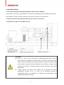
2. The Outline Dimension Drawings and Controller Wiring
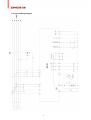
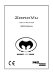
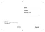
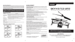
2.1 Outline dimensions of the controller
Wall-mounted type
Vertical type
6
2.2 Following Details:
Module Dimensions
W120mm×H102mm
Panel Cutout
W110mm×H92mm
Thickness
D48mm(without connection))
7
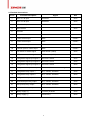
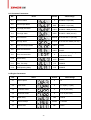
2.3Terminal Connections:
Pin no.
Function Description
Signal
Dim
1
GEN. VL1-N input
0-300Vac
1mm²
2
GEN. VL2-N input
0-300Vac
1mm²
3
GEN. VL3-N input
0-300Vac
1mm²
4
GEN. Neutral
5
Not used
6
Not used
7
I1 Gen current input
0-5A
2.5mm²
8
I2 Gen current input
0-5A
2.5mm²
9
I3 Gen current input
0-5A
2.5mm²
10
Common port for current input
0-5A
2.5mm²
11
LOP sensor or switch signal
LOP sensor (<2KΩ)
1mm²
12
HET sensor or switch signal
HET sensor (<2KΩ)
1mm²
13
Configurable digital input signal 1
low level is active
1mm²
14
Configurable digital input signal 2
low level is active
1mm²
15
Configurable digital input signal 3
low level is active
1mm²
16
Charge excitation power output
if not used, do notconnect to negative
1mm²
17
Configurable relay output 1
N.O. contact, 3A/30Vdc
1mm²
18
Configurable relay output 2
N.O. contact, 3A/30Vdc
1mm²
19
Configurable relay output 3
N.O. contact, 3A/30Vdc
1mm²
20
GCB close/open relay output
N.O. contact, 3A/30Vdc
1mm²
21
Start (Crank) relay output
N.O. contact, 3A/30Vdc
1mm²
22
Fuel solenoid relay output
N.O. contact, 3A/30Vdc
1mm²
23
Battery supply {+}
12V/24V (8-35Vdc
1mm²
24
Battery supply {-}
continuous)
1mm²
1mm²
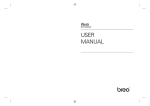
8
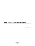
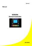
2.4 Typical Wiring Diagram
9
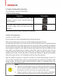
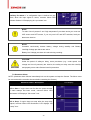
3. Panel Operation
The operation panel consists of 3 sections: LCD display measuring parameters,LED indicator for
common failure, and push buttons for Genset and selection ofcontrol modes.
The LCD circularly displays different measuring parameters. When failure occurs,LCD displays the
corresponding fault icon. LCD also has a backlight so that the operator can clearly read information day
or night. After pressing any button the backlight will automatically turn off in a certain time.
The LCD display and its control push buttons provide a friendly operation interface for the operator to
conveniently read information and set running parameters.
Control buttons and LED
Function Description
Scroll Push Button
Enter into submenu / Modify / confirm modification / scroll menu to
display.
MUTE / LAMP TEST Push Button
When failure occurs, alarm buzzer sounds. Pressing mute button will
mute the sound. LCD displays mute icon. Press and hold mute button for
2sec, all LED illuminate simultaneously.
AUTO Push Button / LED
The push button is used for selecting “AUTO mode”. When the controller
is running in AUTO mode, the LED above the push button illuminates.
The activation and deactivation of the “remote start signal input” controls
the starting and stopping of the Genset.
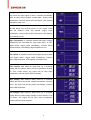
MAN Push Button / LED
The push button is used for selecting “MAN mode”. When the controller is
running in MAN mode, the LED above the push button illuminates. The
Start and Stop push buttons control the starting and stopping of the
Genset.
START / VALUE INCREASE “+” Push Button
The push button is used for MANUALLY starting the Genset .When the
controller is in MAN mode, press this push button will start the generator.
When in parameter setting mode, this push button is used to increase
values.
STOP / RESET / VALUE DECREASE “-” Push Button
The push button is used to MANUALLY stop the Genset. When the
controller is in MAN mode, press and hold this button more than 2sec to
stop the Genset.
If failure occurs, press this push button, the shutdown alarm lockout will
be cleared.
When in parameter setting mode, this push button is used to decrease
values.
COMMEN FAILURE LED
LED will flash when pre-alarm (Warning) occurs.
LED will illuminate permanently when shutdown alarm occurs.
10
Tag
4. Installation Guide
4.1The cutout dimensional drawing installed on panel as above attached.
The controller is secured by 2 special fittings. The shock-proof equipment must be installed if the enclosure
that installed on controller is directly installed on Genet body or other heavy vibrant device.
4.2 Please read above Typical Wiring Diagram fig 2.3 for wiring connections.
4.3 Installation of engine LOP and HET sensors:
CAUTION:
Pin no. “11” and “12” is for “LOP sensor or switch signal” and “HET sensor or
switch signal” input respectively. Either switch or sensor can be chosen. When
sensor is used, according to the actual situation, increase the cross section
area of cable to reduce the cable resistance from controller to engine, which
ensures the accuracy of measured values for both oil pressure and engine
temperature.
If both switches and sensors are required for oil pressure and engine
temperature, connect Pin no. “11” and “12” as above,and connect 2
configurable inputs to the switches of oil pressure and temperature, then
configure parameters by setting.
11
5. Control and Operation Instruction
The controller has 2 modes: AUTO and MAN.
5.1Operation Mode Setting:
Operation
Press
“AUTO”
button
(continuous
Description
2sec)
When
controller is running in “AUTO” mode,LED above push
button illuminates.
Press “MAN” button (continuous 2sec) When controller
is running in “MAN” mode, LED above push button
illuminates.
NOTE: Only one mode of above 2 modes can be selected.
5.2 AUTO control Sequence:
Controller is in “AUTO” mode.
First of all, define one of the configurable inputs as Remote Start Signal.
When the remote start signal is active, the controller implements following procedure:
The Start delay timer begins to count, when it times out the Preheat relay output is energized (if preheat
function is selected), the timer starts. When it times out, the fuel relay output is energized, and operates
the fuel solenoid of the engine. After 300ms delay, the start (crank) relay output is energized; the start
motor engages and begins to crank. When the engine speed reaches the crank cutout RPM, the start
relay output is de-energized and the safety-on delay starts. When the safety-on times out,if the
controller detects that the parameters of the Genset such as voltage, frequency,oil pressure, coolant
temperature are normal, and no other failure is detected this indicates the Genset has successfully
started and running normally. The LCD displays the Genset measuring parameters.
When the voltage and frequency of Generator is normal, Gen. Normal LED illuminates, the timer for
Gen. On delay is activated, when it times out, GCB close/open relay closes, then the transfer switch
switches on Gen. The Gen Aux. Switch’s contact feeds back a signal to a configurable input on our
controller. GCB closed LED illuminates.
NOTE:
When the remote start signal is active, the start delay timer starts. During this
period, if remote start signal is deactivated, the start delay timer is immediately
terminated; the controller will recovers to its original standby status.
During the period of crank or idle, if remote start signal is deactivated,
controller stops the start procedure and recovers to original standby status.
12
NOTE:
While cranking, engine ignites. The start motor will power off when the output
frequency of generator reaches the preset value (configurable crank cutout
value), or if there are one of the following conditions occur:
A. Generator’s voltage reaches 80% of rated voltage;
B. Cranking time’s up,
C. LOP switch is opened and the delay time’s up.
Controller can not implement crank procedure if the frequency of generator
reaches the preset value (configurable cranking cutout value) or LOP switch is
opened.
CAUTION:
To avoid damage to the start motor please make sure the generator’s voltage is
higher than 15V (measurable voltage of the controller) while cranking, since the
crank cutout signal is sensed from the generator voltage and frequency.
NOTE:
Above control procedure, assumes that one of configurable inputs has been
configured as Gen Aux. Switch Closed and connects the switch’s N.O. Aux.
contact signal to this port. If you do not configure an input as Gen Aux. Switch
Closed, then the GCB closed LED illuminates is only an indication that the GCB
close/open relay should have been closed.
If you have selected idle function, the idle relay will be closed at the same time as the crank relay is
closed. The timers of idle and safety-on delay will begin counting down at the same time, and in priority
to display the shorter one on the LCD, and the following procedure is the same as above.
During the crank period, if the engine can not ignite and controller will not output start signal during
crank rest, Fail to Start icon on LCD flashes at this time. Once crank rest timer times out the start relay
energizes once again and will attempt to start engine again.
The procedure above will be repeated until engine successfully ignites or reaches the preset number of
crank attempt. However, if any failure occurs during crank, controller will stop cranking immediately and
only can be reused after clearing failure and reset.
Fail to Start: when the above procedure repeats again and again and reaches the preset number of
crank attempt, the crank relay output is then de-energized. The common failure LED illuminates and the
LCD displays Fail to Start icon.
13
CAUTION:
If Fail to Start occurs, operator must check the whole Genset system to find reason
for failure, only after clearing the failure can press “STOP/RESET” button to relieve
fault lock out status, and restart the Genset.
Generator shutdown sequence:
When the remote start signal is de-activated, the cool down delay timer begins to count. When it times
out, the fuel relay output de-energizes, open the fuel solenoid immediately, generator stops and goes to
standby status.
Fail to stop: When cool down times out, the fuel relay output de-energizes, stop delay timer begins.
When it times out, if controller detects that the voltage and frequency of generator or oil pressure of
engine are greater than the preset values, the common failure LED illuminates and the LCD displays
Fail to stop icon.
NOTE:
After stop failure, the controller will not energize the crank relay output if the failure
hasn’t been removed and the controller reset.
5.3 MANUAL control sequence:
Controller is in “MAN” mode.
Generator starting sequence:
Press “START” push button, the fuel relay output is energized, and operates the fuel solenoid of the
engine. After 300ms delay, the start relay output is energized, the start motor engages and begins to
crank. When the engine speed reaches the crank cutout RPM, the start relay output is de-energized
and the safety-on delay starts. When it times out, if the controller detects that the parameters of the
Genset such as voltage, frequency, oil pressure and coolant temperature are normal, and no other
failure is detected this indicates the Genset has successfully started and running normally. The LCD
displays the Genset measuring parameters.
When generator is running normally, GCB close/open relay will not close automatically. Manually close
the Gen switch, Gen is on load, the Gen Aux. Switch’s contact feeds back the signal to a configurable
input on our controller, Gen. Normal LED illuminates.
NOTE:
When the controller is in “MANUAL” mode and Gen. Normal LED illuminates, you
must define one configurable input as Gen Aux. Switch Closed and connect the
switch’s N.O. Aux. contact signal to this port, otherwise the GCB closed LED will
not illuminate.
14
5.4 The start and stop sequence of engine whose fuel solenoid is N. O. type (energize to stop):
Start control sequence:
During the starting sequence, the fuel output relay of controller will not energize, fuel solenoid is no
power, so no signal is required for fuel solenoid to activate.
Stop control sequence:
During the stopping sequence, the fuel relay output energizes, the fuel solenoid is on power and
energizes, and the engine begins to stop. After a delay (same as stop delay) fuel relay de-energizes,
cutting off the supply for the fuel solenoid.
Other control sequence is same as engine whose fuel solenoid is N. C. type (energize to run).
5.5 Idle function:
For idle function configure one of the configurable outputs as idle.
Refer to the flow chart 5.7 for start and stop for idle control flows.
5.6 Preheat function:
For Preheat function, configure one of the configurable outputs as Preheat. The controller has 3
selectable preheat control modes as below:
Mode 1 — during preheat time, preheat relay output energizes.
Mode 2 — during preheat time, preheat relay output energizes until the successful ignition.
Mode 3 — during preheat time, preheat relay output energizes until safety-on delay times out.
During crank period, the Preheat relay output will not energize in any of above modes.
Refer to the flow chart 5.7 for start and stop for Preheat control flows.
When the Preheat relay output energizes, LCD displays the icon of preheat operating status:
15
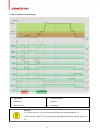
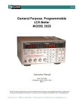
5.7 Flow chart for start and stop
T1-start delay
T4-safety-on delay
T2-crank time
T5-idle time
T3-pre-heat time
T6-stop delay
NOTE:
If T4 is longer than T5, low oil pressure protection is ignored during T5.
If T4 is shorter than T5, low oil pressure protection becomes effective after T4 in
T5.
16
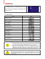
6. Measure and Display Data
Gen phase voltage L1-N L2-N L3-N
Gen line voltage L1-L2 L2-L3 L3-L1
Generator current I1 I2 I3
Generator frequency Hz
Engine speed RPM (derived from generator frequency)
Engine oil pressure BAR / PSI (signal from engine LOP sensor)
Engine coolant temperature ℃/℉ (signal from engine HET sensor)
Battery voltage Vdc
Running hours h
17
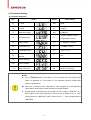
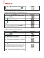
7. Pre-alarm and Shutdown Alarm
7.1 Pre-alarm (Warning)
NOTE: (Pre-alarms (Warnings) are non-critical failure conditions and do not affect the operation of the
generator system, they serve for drawing the operators’ attention to an undesirable condition so they
can remove it to ensure continuous running of the system. When Pre-alarms occur, the LED indicator
flashes, but failure will not be locked out and the unit will not shutdown. Once the Pre-alarm failure is
removed the Pre-alarm LED will automatically turn off.)
Pre-alarm / Description
LCD Display
Fail to Charge: After safety-on times up, if the charging voltage
from the excitation contact of alternator is lower than the “charge
V Pre-alarm”, the common failure LED indicator (
) flashes,
the LCD displays Charge failure icon:
Battery Low Voltage: if controller detects that battery voltage
has fallen below the “low batt. pre-alarm”, common failure LED
indicator flashes. For example, “low batt. pre-alarm” preset as:
23.6V, when battery voltage falls below this value, LCD flashing
low value icon:
Battery High Voltage: if controller detects that battery voltage
has exceeded the “high batt. pre-alarm”, common failure LED
indicator flashes. For example, “high batt. pre-alarm” preset as:
28.2V, when battery voltage exceeds this value, LCD flashing
high value icon:
Low Oil Pressure: if controller detects that the engine oil
pressure has fallen below the “low oil-press pre-alarm” after the
safety-on timer expired, common failure LED indicator flashes.
For example, “low oil-press pre-alarm” preset as: 2.2BAR, when
engine oil pressure falls below this value, LCD flashing low value
icon:
High Temperature: if controller detects that engine coolant
temperature has exceeded the “high temp pre-alarm”, common
failure LED indicator flashes. For example, “high temp pre-alarm”
preset as: 95℃, when engine coolant temperature exceeds this
value, LCD flashing high value icon:
18
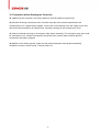
Over speed: if engine speed exceeds the “over speed prealarm”, common failure LED indicator flashes. For example, “over
speed pre-alarm” preset as: 1600RPM, when engine speed
exceeds this value, LCD flashing high value icon:
Under speed: if engine speed falls below the “under speed prealarm” after the safety-on timer has expired, common failure LED
indicator flashes. For example, “under speed pre-alarm” preset
as: 1440RPM, when engine speed falls below this value, LCD
flashing low value icon:
Over Current: if any phase output current of generator exceeds
the “over current pre-alarm” after the safety-on timer has expired,
common failure LED indicator flashes. For example, “over current
pre-alarm” preset as: 850A, when any phase output current of
generator exceeds this value, LCD flashing high value icon for
corresponding phase:
High Voltage: if controller detects that any phase output voltage
of generator has exceeded the “Vac high pre-alarm” after the
safety-on timer has expired, common failure LED indicator
flashes. For example, “Rated ph-voltage” preset as: 220V, “Vac
high pre-alarm” preset as: 115%, when any phase output voltage
of generator exceeds this value, LCD flashing high value icon for
corresponding phase:
Low Voltage: if controller detects that any phase output voltage
of generator has fallen below the “Vac low pre-alarm” after the
safety-on timer has expired, common failure LED indicator
flashes. For example, “Rated ph-voltage” preset as: 220V, “Vac
low pre-alarm” preset as: 90%, when any phase output voltage of
generator falls below this value, LCD flashing low value icon for
corresponding phase:
Low Fuel Level: If a configurable input has been defined as low
fuel level, when the input signal is active, common failure LED
indicator flashes, LCD displaying low fuel level icon:
19
Auxiliary Pre-alarm: if a configurable input is defined as prealarm, when the input signal is active, common failure LED
indicator flashes. LCD displaying Aux. pre-alarm icon:
NOTE:
To make “low oil pressure” and “high temperature” pre-alarm active,you must use
LOP sensor and HET sensor, if you only use LOP and HET switches, both prealarms are inactive.
NOTE:
Controller continuously detects battery voltage during standby and Battery
Low/High Voltage pre-alarms are active.
Battery Low Voltage pre-alarm is inactive during cranking.
CAUTION:
Under the period of safety-on delay, some pre-alarms (e.g.: under speed, low
voltage and low oil pressure) are inactive, the safety-on delay must be carefully
and properly set to make Genset have full protection.
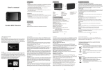
7.2 Shutdown Alarm
NOTE: (shutdown alarm failures immediately lock out the system and stop the Genset. The failure must
be removed and the controller be reset before restarting the Genset.)
Shutdown Alarm / Description
Fail to Start: if engine does not fire after the preset number
of crank attempt has been made, common failure LED
illuminates. LCD displays “fail to start” icon:
Fail to Stop: if engine does not stop after the stop delay
expired, common failure LED illuminates. LCD displays “fail
to stop” icon:
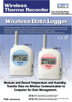
20
LCD Display
Emergency Stop: define a configurable input as emergency
stop, when the input signal is active, controller immediately
stops all relay control outputs except alarm, engine stops
immediately. Common failure LED illuminates, LCD displays
“emergency stop” icon:
Low Oil Pressure: if controller detects that the oil pressure
still falls below “low oil-press alarm” or LOP switch closes
after the safety-on timer has expired, engine stops
immediately, common failure LED illuminates. LCD displays
low oil pressure icon:
High Temperature: if controller detects that engine coolant
temperature has exceeded the “high temp alarm” or HET
switch closes, engine stops immediately, common failure
LED illuminates. LCD displays high temperature icon:
Over speed: if controller detects that engine speed exceeds
“over speed alarm”, engine stops immediately, common
failure LED illuminates. LCD displays over speed icon:
Over Current: After safety-on delay time up, if controller
detects that any phase output current of generator exceeds
the “over current alarm”, the engine will be shut down
immediately, common failure LED illuminates.
High Voltage: After safety-on delay times up, if controller
detects that one of the phase voltage exceeds the “Vac high
alarm”, the engine will be shut down immediately, common
failure LED illuminates.
Low Voltage: After safety-on delay times up, if controller
detects that any phase output voltage is lower than the “Vac
low alarm”, the engine will be shut down immediately,
common failure LED illuminates.
21
Auxiliary Failure: If a configurable input has been
defined as Shutdown Alarm, when the input signal is active,
common failure LED illuminates. LCD displays Aux.
shutdown alarm icon:
Code Table for Failure:
Name
Code
CHARGE FAILURE
BATT. UNDER VOLT
BATT. OVER VOLT
START FAILURE
STOP FAILURE
EMERGENCY STOP
LOW OIL PRESS
ENGINE HIGH TEMP
OVER SPEED
UNDER SPEED
OVER CURRENT
GEN. OVER VOLT
GEN. UNDER VOLT
P-SENSOR OPEN
NOTE:
Engine speed signal is derived from the frequency of generator output voltage,
it is used for control and failure protection parameters, for the convenience of
user, some data is expressed by RPM, RPM = Hz * 60 / pair of poles.
While the Genset is running, if there are high coolant temperature, low oil
pressure or over speed failure occurs, the controller will shutdown it
immediately without delay. During the cool down period, if there is low oil
pressure failure, the alarm will be active no matter if there is idle function.
CAUTION:
During the period of safety-on delay, low oil pressure protection is inactive. To
avoid starting an engine with no oil, you must make sure the oil levels are normal
and the safety-on delay shall be carefully and properly set for the first
commissioning.
22
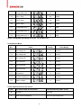
8. Parameters Setting
8.1 System Parameters:
NO.
Items
Preset
Value Range
1.1
CT ratio
100
1-2000
1.2
VT ratio
1.0
1.0-100.0
1.3
Rated ph-voltage
220
45-9999Vac
1.4
AC voltage type
3
1-3 ((3 for 3 phase 4 wire,1
for signal phase 2 wire)
1.5
Startup mode
0
0-1 / 0(MAN) /1 (AUTO)
1.6
Oil pressure unit
0
0-1 (0-BAR,1-PSI,)
1.7
Temperature unit
0
0-1 (0-℃,1-℉,)
1
1-247
Communication
1.8
address
1.9
Default settings
1.10
On-line update
1.11
Page scroll time
0S
0-10 S / 0 (not used)
NOTE:
For 1.5
Startup Mode, if you select “1”, the controller will be in AUTO mode
when it is powered on; if you select “0”, the controller will be in MAN mode
when it is powered on.
After the oil pressure and temperature units changed, the corresponding
failure alarm value must be reset according to actual situation.
Engine speed is calculated by the number of “pair of poles”. RPM=Hz * 60 /
pair of poles, when rated frequency is 50 Hz,if pair of poles set as “2”, then
running speed is 1500 RPM, if pair of poles set as “1” , then running speed is
3000 RPM.
23
8.2 Generator Parameters:
NO.
Items
2.1
Vac low alarm
2.2
Preset
Value Range
0
20-200% / 0 (not set)
Vac low pre-alarm
90%
20-200% / 0 (not set)
2.3
Vac high pre-alarm
115%
20-200% / 9999 (not set)
2.4
Vac high alarm
9999
20-200% / 9999 (not set)
2.5
Hz low alarm
45.0Hz
10.0-100.0Hz / 0 (not set)
2.6
Hz high alarm
57.0Hz
10.0-100.0Hz /999.9 (not set)
2.7
Over current pre-alarm
100%
0-200%
2.8
Over current alarm
150%
0-200%
2.9
Over current action
0
2.10
Alarm delay
10 S
0-600 S
2.11
Gen. On delay
5S
1-9999 S
2.12
GCB opening delay
5S
1-9999 S
0-1 (0- electrical tripping,
1-shutdown alarm)
8.3 Engine Parameters:
NO.
Items
Preset
Value Range
3.1
Pair of poles
2
1-4
3.2
Fuel mode
0
0-1 / 0(NC) / 1 (NO)
3.3
T-sensor mode
3
0-15 / 0 (not used)
3.4
P-sensor mode
4
0-15 / 0 (not used)
3.5
Start delay
3.6
Crank attempt
3.7
Crank time
10S
3 times
8S
24
0-300 S
1-10 times
0-30 S
3.8
Crank rest
15S
3.9
Crank cutout RPM
3.10
Idle delay
3.11
Preheat delay
3.12
Preheat
3.13
Safety-on delay
60S
0-600 S
3.14
Cool down delay
300S
0-600 S
3.15
Stop delay
20S
0-60 S
3.16
Under speed alarm
3.17
Under speed Pre-alarm
1440RPM 0-9999 RPM / 0 (not set)
3.18
Over speed Pre-alarm
1600RPM 1-9999 RPM / 9999 (not set)
3.19
Over speed alarm
1710RPM 1-9999 RPM / 9999 (not set)
3.20
low oil-press alarm
1.4BAR
0-45.0 BAR
3.21
low oil-press pre-alarm
2.2BAR
0-45.0 BAR
3.22
high temp pre-alarm
95℃
70-320℃ / 9999 (not set)
3.23
high temp alarm
105℃
70-320℃ / 9999 (not set)
3.24
low batt. pre-alarm
8.0V
1.0-25.0V / 0 (not set)
3.25
high batt. pre-alarm
28.0V
1.0-35.0V / 99.9 (not set)
3.26
charge V Pre-alarm
8.0V
1.0-25.0V / 0 (not set)
300RPM
0
0-300 S
1-9999 RPM
0-9999 S
3S
1
0-300S
1-3
0RPM
0-9999 RPM / 0 (not set)
8.4Input and Output Setting:
NO.
Items
Preset
Value Range
4.1
Configurable input 1
8
0-12
4.2
Configurable input 2
7
0-12
25
4.3
Configurable input 3
12
0-12
4.4
Input 1 delay
2S
0-60S
4.5
Input 2 delay
2S
0-60S
4.6
Input 3 delay
2S
0-60S
4.7
Configurable relay 1
2
0-80
4.8
Configurable relay 2
3
0-80
4.9
Configurable relay 3
5
0-80
NOTE: configurable input delay is only for 1 to 4 codes in 8.7.
8.5 Calibration Menu:
NO.
Items
Preset
Value Range
5.1
Gen voltage V1
0
±10.0%
5.2
Gen voltage V2
0
±10.0%
5.3
Gen voltage V3
0
±10.0%
5.4
Gen current I1
0
±10.0%
5.5
Gen current I2
0
±10.0%
5.6
Gen current I3
0
±10.0%
5.7
Oil pressure
0
±10.0%
5.8
Coolant temperature
0
±10.0%
5.9
Battery voltage
0
±10.0%
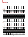
8.6The optional items for P/T-sensor:
Code
The brand model of LOP sensor
The brand model of HET sensor
0
not used
not used
1
close for low oil pressure
close for high temperature
26
2
open for low oil pressure
open for high temperature
3
VDO 5 bar
VDO 120 ℃
4
VDO 10 bar
VDO 150 ℃
5
Datcon 7 bar
Datcon
6
Murphy 7 bar
Murphy
7
Pre-set 1
PT100
8
Pre-set 2
Pre-set 1
9
Pre-set 3
Pre-set 2
10
Pre-set 4
Pre-set 3
11
configured by user
Pre-set 4
12
configured by user
NOTE:
When the controller leaves factory, the optional types and functions of LOP sensor
and HET sensor have been preset as the above table. If the using sensor is not
listed in this table, the user can select “configurable”, and write sensor parameters
to controller via software.
LOP sensor parameter addendum:
VDO 5 bar:
P(Bar)
0
0.5
1.0
1.5
2.0
2.5
3.0
3.5
4.0
4.5
5
P(PSI)
0
7.3
14.5
21.8
29.0
36.3
43.5
50.8
58.0
65.3
72.5
R(Ω)
11
29
47
65
82
100
117
134
151
167
184
P(Bar)
0.0
1.0
2.0
3.0
4.0
5.0
6.0
7.0
8.0
9.0
10.0
P(PSI)
0
14.5
29.0
43.5
58.0
72.5
87.0
101.5
116.0
130.5
145.0
R(Ω)
10
31
52
71
90
106
124
140
155
170
184
VDO 10 bar:
27
Datcon 7 bar:
P(Bar)
0.0
0.7
1.4
2.1
2.8
3.4
4.1
4.8
5.5
6.2
6.9
P(PSI)
0
10.0
20.0
30.0
40.0
50.0
60.0
70.0
80.0
90.0
100.0
R(Ω)
240
200
165
135
115
95
78
63
48
35
25
P(Bar)
0.0
0.7
1.4
2.1
2.8
3.4
4.1
4.8
5.5
6.2
6.9
P(PSI)
0
10.0
20.0
30.0
40.0
50.0
60.0
70.0
80.0
90.0
100.0
R(Ω)
240
205
171
143
123
103
88
74
60
47
33
P(Bar)
0.0
1.0
2.0
3.0
4.0
5.0
6.0
7.0
8.0
9.0
10.0
P(PSI)
0
14.5
29.0
43.5
58.0
72.5
87.0
101.5
116.0
130.5
145.0
R(Ω)
15
31
49
66
85
101
117
132
149
164
178
P(Bar)
0.0
1.0
2.0
3.0
4.0
5.0
6.0
7.0
8.0
9.0
10.0
P(PSI)
0
14.5
29.0
43.5
58.0
72.5
87.0
101.5
116.0
130.5
145.0
R(Ω)
30
41
65
88
110
115
145
150
172
185
190
Murphy 7 bar:
Pre-set 1:
Pre-set 2:
Pre-set 3:
P(Bar)
0
1.7
3.4
5.2
6.9
8.6
10.3
P(PSI)
0
25
50
75
100
125
150
R(Ω)
21
36
52
72
84
100
120
Pre-set 4:
P(Bar)
1.0
2.0
3.0
4.0
5.0
6.0
7.0
8.0
9.0
P(PSI)
14.5
29.0
43.5
58.0
72.5
87.0
101.5
116.0
130.5
R(Ω)
195
155
127
107
88
72
61
54
48
28
HET sensor parameter addendum:
VDO 120℃:
T(℃)
40
50
60
70
80
90
100
110
120
130
140
T(℉)
104
122
140
158
176
194
212
230
248
266
284
R(Ω)
291
197
134
97
70
51
38
29
22
18
15
T(℃)
50
60
70
80
90
100
110
120
130
140
150
T(℉)
122
140
158
176
194
212
230
248
266
284
302
R(Ω)
322
221
155
112
93
62
47
37
29
23
19
T(℃)
40
50
60
70
80
90
100
110
120
130
140
T(℉)
104
122
140
158
176
194
212
230
248
266
284
R(Ω)
900
600
400
278
200
141
104
74
50
27
4
T(℃)
40
50
60
70
80
90
100
110
120
130
140
T(℉)
104
122
140
158
176
194
212
230
248
266
284
R(Ω)
1029
680
460
321
227
164
120
89
74
52
40
T(℃)
-100
-50
0
20
40
60
80
100
150
200
300
T(℉)
-148
-58
32
68
104
140
176
212
302
392
572
R(Ω)
60
81
100
108
116
123
131
139
157
176
212
T(℃)
20
30
40
50
60
70
80
90
100
110
120
T(℉)
68
86
104
122
140
158
176
194
212
230
248
R(Ω)
900
600
420
282
152
113
86
62
48
40
30
VDO 150℃:
Datcon:
Murphy:
PT100:
Pre-set 1:
Pre-set 2:
T(℃)
30
50
60
70
80
90
100
110
120
T(℉)
86
122
140
158
176
194
212
230
248
R(Ω)
980
400
265
180
125
90
65
50
38
29
Pre-set 3:
T(℃)
20
30
40
50
60
70
80
90
100
110
120
T(℉)
68
86
104
122
140
158
176
194
212
230
248
R(Ω)
805
540
380
260
175
118
83
58
42
30
21
Pre-set 4:
T(℃)
28
35
40
50
60
70
80
90
95
98
T(℉)
82
95
104
122
140
158
176
194
203
208
R(Ω)
579
404
342
250
179
136
103
77
67
63
8.7 The optional items for configurable input:
Code
Optional Function
NOTE
0
not used
1
Pre-alarm (active immediately)
low level is active
2
Shutdown Alarm (active immediately)
low level is active
3
Pre-alarm (active after safety-on delay)
low level is active
4
Shutdown Alarm (active after safety-on delay)
low level is active
5
LOP switch
low level is active
6
HET switch
low level is active
7
Emergency stop
low level is active
8
Remote start signal
low level is active
9
Reserved
low level is active
10
Gen Aux. Switch closed
low level is active
11
Low fuel level
low level is active
12
Lamp test
low level is active
30
8.8 The optional items for configurable output:
Code
Failure Type Define
0
Not used
1
Over current tripping
2
Alarm
3
Pre-alarm
4
Idle 0 (N.C.)
5
Preheat
6
Speed up
7
Reserved
8
Fuel pump control
9
Running
10
System in AUTO mode
11
Reserved
12
System in MAN mode
13
Reserved
14
Idle 1 (N.O.)
15
Reserved
16
GCB failure (within 5s)
17
Fail to start
NOTE:
If define one configurable relay as Speed up, the relay will close after the engine
has successfully started. If there is idle function, the relay will close after idle timer
times out.
31
9. LCD Display and Menu System
Using a backlit TN type LCD to display data and information. After pressing any push button the
backlight will automatically turn off in a preset time. In normal operating status, you can set the page
scroll time to circularly display each page of measuring data. Press “
“manually scrolls to view each
measuring data. When failure occurs, LCD displays the corresponding failure icon.
Press and hold “
page, press “
” button 2sec to enter into parameters setting menu, then use “
“ again to select the required modify item,press “
when prompted to enter password, then use “
“or”
“ or “
“ or “
” to scroll
“LCD displays 0000,
“ to modify the first digital value, press
“
”move to modify the next one, after this, the first digital value will be displayed as “H”. Press
“
”to confirm after the password is set as 2213, then you can modify parameters. Otherwise it will
prompt to key in password again. Press and hold “
” for more than 2sec to quit parameters setting
mode after finishing configuration.
9.1 Static LCD displays
Controller is in standby status, circularly displays each measuring data:
→
Controller is normally running, circularly displays each measuring data:
→
→
→
→
NOTE:
When T-sensor or P-sensor is set as “not used”, LCD will not display related
measuring data.
32
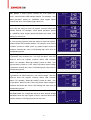
9.2 Setting running parameters
F or example: (setting CT rate at 1000/5, then CT should be set at 200)
Operation
Press and hold “
Description
” 2sec, to enter into parameter settings
menu,then LCD displays:
press “
”, then LCD displays:
press ”
“ prompted enter password, then LCD displays:
press “
“ or “
“
” again, press “
“enter the password: (2213), then press
“ or “
“change parameter, change
at 200, then LCD displays:
press “
” to confirm,then press “
“, then LCD displays:
press “
” again to quit, or press and hold “
” more than
2s also can quit, then LCD displays:
For example: (setting controller crank attempt at 2)
Operation
Press and hold “
Description
” 2sec, to enter into parameter settings
menu,then LCD displays:
Press “
” 28 times and then press “
press “
” prompted enter password, then LCD displays:
Key in password: (2213), press “
”, then LCD displays:
”, then LCD displays:
33
Press“
“
“ or “
“ change parameter, change at 2, Press
” to confirm change, and then press and hold “
” for
more than 2sec will quit parameters setting menu.
For example: (resume all parameters of controller to factory default)
Operation
Press and hold “
Description
” 2sec, to enter into parameter settings
menu,then LCD displays:
Press “
” 8 times, then LCD displays:
press “
” prompted enter password, then key in password:
(2213)
Press “
” to recover default, press and hold “
” for more
than 2sec will quit parameters setting menu.
For example: (set controller as online program mode)
Operation
Press and hold “
Description
” 2sec, to enter into parameter settings
menu,then LCD displays:
Press “
” 9 times and then LCD displays:
press “
” prompted enter password, then key in password:
(3132)
Press “
” again to enter into online program mode, use the
communication cable and the software to program, please
make sure the power supply is normal during programming,
the controller will reset automatically after programming. If
you have entered into this mode already, but you do not
program, you need to turn the controller off to exit this mode.
34
10. Preparation before Starting the Controller
10.1 Make sure the controller is correctly installed to meet the ambient requirements.
10.2 Confirm all wiring connections of the controller meet the correct electric specification and
corresponding to “2.3 typical wiring diagram”. Ensure the correct polarity of the DC supply source and
that it has been protected by an external fuse. Otherwise damage to the controller may occur.
10.3 We recommend mounting an “Emergency Stop” button externally. The emergency stop input could
be connected to N.O. contact of emergency stop push button, and the other contactor point be
connected to the battery negative.
10.4 Switch on DC working power, make sure the preset parameters meet practical operating
conditions, such as P-sensor mode, T-sensor mode, etc.
35
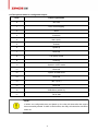
11. Technical Specification
DC working power
Voltage range: 12V/24V (8-35V continuous)
Cranking drop outs: 0V for 100mS, assuming dc supply was at least 10V before
dropout and recovers to 5V
Max. operating current: @12V 180mA, @24V 90mA
Standby current: TBA
AC input voltage: phase voltage15-300Vac RMS (AC frequency≥40 Hz)
AC input frequency: 3-70Hz (voltage ≥15V)
Accuracy: 1%
Aux Control relay output: 3A/30Vdc
Start relay output: 3A/30Vdc
Fuel relay output: 3A/30Vdc
Protection: IP65 (when correctly installed)
Operating ambient temperature: -20 to 70℃
Storage ambient temperature: -30 to 80℃
36
37