1
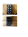
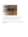
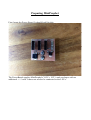
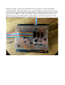
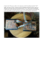
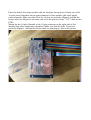
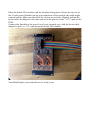
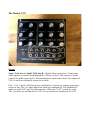
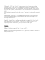
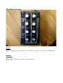
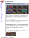
Gotharman’s MiniProphet
Pro-One clone with extras in Eurorack Modules
User Manual
Thank you very much for purchasing / consider to purchase my MiniProphet
eurorack modules.
Please read this manual before setting up your MiniProphet, to avoid malfunction
caused by wrong handling.
Foreword
I once had a Sequential Pro One, that I was very happy with. It is a very great
sounding and versatile synth. Problem with it was, that it was very unstable, and I
felt like I spended more time repairing it, than playing on it, and I certainly did not
dared to use it live (but I did wanted to).
Therefore I designed the first MiniProphet desktop. A small easy portable package,
that was very easy to bring for live shows, and since all parts except for the special
CEM chips were completely new, it was much more stable than the original one.
A MIDI to CV interface were built in for easy connection to a keyboard, and an
extra filter were added for more sonic experimentation.
A while after I had sold all the 3 MiniProphet desktops that were built, and I started
to make a new one for myself, I got the idea, to try to make it in eurorack format, to
get this great sound, with even more flexibility.
MiniProphet EuroRack was born….
Gotharman, July 2014
Included in the MiniProphet Eurorack set
1 double VCO module
1 double VCF module
1 double ADSR Envelope module
1 double LFO module
1 Power Board
4 pcs 16 pole flatcables with connectors 30 cm long for power connections.
2 pcs 10 pole flatcables with connectors for internal connections.
The cables will come with one end attached to some of the modules.
Make sure to locate all of these items. If something is missing, please get in touch
with Gotharman.
Preparing MiniProphet
First, locate the Power Board. It should look like this:
The PowerBoard supplies MiniProphet’s VCO’s, VCF’s and envelopes with an
additional +/- 5 volts. It does not need to be connected to the LFO’s.
Then locate the double VCO module, and place it with its faceplate facing down:
Now, mount the PowerBoard on the power connector of the double VCO module,
using the 16 pin receptable header on the powerboard. Make sure that all 16 pins are
perfectly alligned, and that the ”-12V” marks on both boards are alligned too.
Bottomview of the PowerBoard mounted on the double VCO:
Mount one of the 10-pole flatcables to the 10 pin connector on the top side of the
double VCO module (this cable might come mounted). Make sure that all 10 pins are
perfectly alligned, and that the brown cable are alligned to the same side as on the
picture:
Mount one of the 16-pole power flatcables on the connector on the PowerBoard
marked ”INPUT” (this cable might come mounted). Make sure that all of the 16 pins
are perfectly alligned, and that the brown cable are alligned to the same side as on the
picture (to the ”INPUT” mark on the PCB). When you mount MiniProphet in your
Eurorack system, this cable should be connected to your Eurorack power bus, with
the brown cable alligned to pin 1 – minus 12 volts.
Place the double VCF module with the faceplate facing down. Mount one of the 16pole power flatcables on the powerconnector of this module (this cable might come
mounted). Make sure that all of the 16 pins are perfectly alligned, and that the brown
cable are alligned to the same side as on the picture (to the ”-12V” mark on the PCB).
Connect the VCF power cable to the connector on the PowerBoard marked ”VCF”.
Make sure that all of the 16 pins are perfectly alligned, and that the brown cable are
alligned to the same side as on the picture (to the ”VCF” mark on the PowerBoard).
Connect the 10 pole flat cable from the VCO to the 10 pin connector on the right side
of the VCF. Make sure that all of the 10 pins are perfectly alligned, and that the
brown cable are pointing up, like on the picture.
Place the double Envelope module with the faceplate facing down. Mount one of the
16-pole power flatcables on the powerconnector of this module (this cable might
come mounted). Make sure that all of the 16 pins are perfectly alligned, and that the
brown cable are alligned to the same side as on the picture (to the ”-12V” mark on the
PCB).
Mount the last 10-pole flatcable to the 10-pin connector on the right side of this
module (this cable might come mounted). Make sure that all of the 10 pins are
perfectly alligned, , and that the brown cable are pointing up, like on the picture.
Connect the Envelope power cable to the connector on the PowerBoard marked
”ENV”. Make sure that all of the 16 pins are perfectly alligned, and that the brown
cable are alligned to the same side as on the picture (to the ”ENV” mark on the
PowerBoard).
Connect the 10 pole flat cable from the Envelope to the 10 pin connector on the left
side of the VCF. Make sure that all of the 10 pins are perfectly alligned, and that the
brown cable are pointing up, like on the picture.
Your MiniProphet system are now ready to be installed in your Eurorack case.
Connect the ”Input” power flatcable to the power bus of your eurorack case, with the
brown cable alligned to pin 1 or –12V. Mount these 3 modules.
Place the double LFO module with the faceplate facing down. Mount the last one of
the 16-pole power flatcables on the powerconnector of this module (this cable might
come mounted). Make sure that all of the 16 pins are perfectly alligned, and that the
brown cable are alligned to the same side as on the picture (to the ”-12V” mark on the
PCB).
Connect this flatcable to the power bus of your eurorack case, with the brown cable
alligned to pin 1 or –12V, and mount the double LFO module.
Your MiniProphet system should now be ready to use.
Inputs and Outputs of the modules
The Double VCO
Inputs:
Midi In – 5 pole DIN connector. Connect the MIDI out of a MIDI keyboard, a MIDI
sequencer, or any other MIDI device capable of transmitting notes and CC’s, to this.
MiniProphet only receives Note on and off’s, pitch bend and modulation wheel
messages on MIDI channel 2.
CvA – VCO A pitch modulation. Connect any voltage generating source to this. The
CvA knob adjusts the amount of modulation.
FM – VCO A linear FM. Connect any voltage generating source to this. The FM
knob adjusts the amount of FM. When nothing is connected to this, the Triangle
output of VCO B are internally connected to it.
PwmA – VCO A pulsewidth modulation. Connect any voltage generating source to
this. The PwmA knob adjusts the amount of modulation.
Cv1B, Cv2B – VCO B pitch modulation. Connect any voltage generating source to
these. The Cv1B and Cv2B knobs adjusts the amount of modulation.
PwmB – VCO B pulsewidth modulation. Connect any voltage generating source to
this. The PwmB knob adjusts the amount of modulation.
Outputs:
Velo/Rndm – This outputs a new velocity or random voltage between 0 and 5 volts,
according to the Rndm/Velo switch, every time a MIDI note on are received on MIDI
channel 2.
Gate – Outputs a 5 volt gate voltage, every time at least one MIDI note are active.
When no MIDI notes are active, it outputs 0 volts. This can be used to trigger
envelopes.
Kybd – This outputs the latest received MIDI note on’s note number, as a voltage
between -5 and +5 volts, 1V/Oct.
ModWh – This outputs the latest received modulation wheel value, as a voltege
between 0 and 5 volts.
SquA, TriA, SawA, SawB, TriB, SquB – VCO A and B waveform outputs.
Buttons:
Trig – Pushing this will make the Gate output, outputting a trigger. When the 10 pole
”Internal” flatcables are connected, it will send a trigger to the double Envelopes.
Sync – Pushing this will toggle between VCO syncronization on and off. When the
LED is lit, it is on, and VCO A syncronizes to VCO B.
The Double VCF
Inputs:
SquA, TriA, SawA, SquB, TriB, SawB – Double filter input mixer. Connect any
audio signals you want routed through the 2 filters, to these. The respective knobs
controls the audio signal levels. When nothing are connected to these, the outputs of
VCO A and B are internally connected to them.
Cv1 – VCF 1 and 2 CutOff frequency modulation. Connect any voltage generating
source to this. The Cv1 knob adjusts the amount of modulation. This modulation
applies to both VCF1 and 2 at the same time. When the ”Vcf2” switch are in the
”Inv” position, the modulation of VCF2 are inverted to the modulation of VCF1.
Cv2(env2) – VCF 1 and 2 CutOff frequency modulation. Connect any voltage
generating source to this. The Cv2 knob adjusts the amount of modulation. This
modulation applies to both VCF1 and 2 at the same time. When the ”Vcf2” switch
are in the ”Inv” position, the modulation of VCF2 are inverted to the modulation of
VCF1.
When nothing is connected to this, the output of Envelope 2 are internally connected
to it.
VcaCv(env1) – Output VCA level modulation. Connect any voltage generating
source to this. When nothing is connected to this, the output of Envelope 1 are
internally connected to it.
Vca In2 – Usually Filter 1 and 2 goes out through the output VCA. Filter 1 and 2
knobs adjusts the level of each filter. If you however would like Filter 2 to be
replaced by another audio source, you may connect it to this input.
Outputs:
Flt2out – The direct output of Filter 2, before the VCA.
Output – The total audio output from the VCA, adjusted by the Filter 1 and Filter 2
knobs, and the VcaCv.
The Double Envelope
Inputs:
Gate – Triggers the 2 envelopes to start from zero, and go through the ADSR stages.
Outputs:
Env1, Env2 – Envelope 1 and 2 voltage outputs.
The Double LFO
Inputs:
Cv – LFO Rate modulation. Connect any voltage generating source to this. The Cv
knob adjusts the amount of modulation.
Outputs:
Tri, Squ – Triangle and square wave outputs. The rate of these can be adjusted using
the Rate knob and the Rate Cv input. The symmetry of the waveforms can be
adjusted using the Sym knobs.
Internal Connections
If you have connected the 2 10-pole flatcables, as described earlier in this manual,
MiniProphet will have some internal connections. These are cutted off, by plugging
something in to their respective inputs.
List of internal connections:
-All 6 oscillator output waveforms are internally connected to the filters input mixer.
-The envelope gate, from the MIDI interface and the trigger button, are internally
connected to the envelopes gate input.
-The output of envelope 1 are connected to VCA CV.
-The output of envelope 2 are connected to the VCF CV2.
-VCO2 triangle output are connected to VCO1 FM input.
www.gotharman.dk