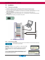
1
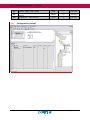
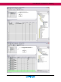
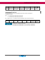
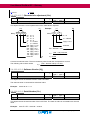
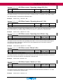
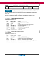
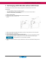
Automation Solutions User Manual Profibus-DP-Gateway 716458 Description of Profibus-DP-Gateway in connection with LOCC-Box-Net 716410 and 716411. Version 1.00 User Manual Profibus-DP – Gateway The user manual is part of the product and contains important information about the handling and the safety. To avoid hazardous situations read the manual before installing the product and using it. Lütze reserves the right to change its products in the interest of technical progress. These alterations need not to be documented in every case. This manual and the contained information have been arranged with the utmost care. The Friedrich Lütze GmbH disclaims liability for literal mistakes and other errors or resulted damages. The named brands and product names in this document are trademarks or registered trademarks by title holder. Copyright 2013 by Friedrich Lütze GmbH. All rights reserved. Friedrich Lütze GmbH Post office box 1224 D-71366 Weinstadt - Großheppach Germany Phone: Fax: E-Mail: Internet: 2 +49/ (0)7151/ 6053-0 +49/ (0)7151/ 6053-277 [email protected] http://www.luetze.com Profibus-Gateway 716458_100_HB_EN User Manual Profibus-DP - Gateway Content 1 General Information ...................................................................... 5 1.1 1.2 1.3 1.4 Symbol Description ........................................................................................... 5 Copyright........................................................................................................... 5 Disclaim of Liability ........................................................................................... 5 Safety ................................................................................................................ 5 1.4.1 1.4.2 1.4.3 1.4.4 1.4.5 2 Content of Manual ..............................................................................................................5 Intended Use.......................................................................................................................6 Operating Employee ...........................................................................................................6 Maintenance .......................................................................................................................6 Decommissioning and Deposal ..........................................................................................6 Gateway – Profibus-DP, 716458 ................................................... 7 2.1 General Information .......................................................................................... 7 2.1.1 2.1.2 2.1.3 2.1.4 2.1.5 2.1.6 2.1.7 Explanation .........................................................................................................................7 Dimensions and Connections .............................................................................................7 Function and Displays ........................................................................................................8 Topology and Structure ......................................................................................................8 LOCCbus – Interface ..........................................................................................................9 Operation system and driver...............................................................................................9 Mounting .............................................................................................................................9 2.2 Installation ....................................................................................................... 10 2.2.1 2.2.2 Structure in principle .........................................................................................................10 Connection to USB ...........................................................................................................10 2.3 Communication via USB ................................................................................. 11 2.4 Communication via Profibus-DP ..................................................................... 11 2.4.1 Terms and Definitions .......................................................................................................11 2.4.2 Description files.................................................................................................................12 2.4.3 Profibus-DP interface ........................................................................................................12 2.4.4 Overview LOCC-Box-Net Modules ...................................................................................12 2.4.5 Baudrates..........................................................................................................................13 2.4.6 Profibus-DP-V1 DS_Read (Overview of instructions) ......................................................13 2.4.7 Configuration in step7 .......................................................................................................14 2.4.8 Parametrization .................................................................................................................16 2.4.9 Process Image ..................................................................................................................16 2.4.9.1 Input-byte .................................................................................................................16 2.4.9.2 Output-byte ..............................................................................................................17 2.4.10 Example for the used instructions .................................................................................18 2.4.10.1 Module type (00h) ...................................................................................................18 2.4.10.2 Module status (10h) ................................................................................................18 2.4.10.3 Module configuration (11h) .....................................................................................18 2.4.10.4 Output voltage (20h) ...............................................................................................19 2.4.10.5 Input voltage (21h) ..................................................................................................19 2.4.10.6 Current Measurement (24h) ...................................................................................19 2.4.10.7 Characteristic adjustment (2Ah) .............................................................................20 2.4.10.8 Software Version (30h) ...........................................................................................20 2.4.10.9 Serial Number (31h) ...............................................................................................20 2.4.10.10 LOCC-Box counter “Operating voltage ON“ (32h) ...............................................21 Profibus-Gateway 716458_100_HB_EN 3 User Manual Profibus-DP – Gateway 2.4.10.11 LOCC-Box Counter “Operating hours (h)” (33h) ..................................................21 2.4.10.12 LOCC-Box counter “Operating hours ON (h)“ (34h) .............................................21 2.4.10.13 LOCC-Box counter “Blown” (35h) .........................................................................21 2.4.10.14 LOCC-Box Counter “Switch on” (36h) ..................................................................21 2.4.10.15 LOCC-Box adjustment (38h) ................................................................................22 2.4.10.16 Adjustment Current range, (I) (39h)......................................................................23 2.4.10.17 Adjustment characteristic, (C) (3Ah).....................................................................23 2.4.10.18 Reset and automatic assigning of node number (80h).........................................23 2.4.10.19 Request „Status node number“ (81h) ...................................................................23 2.4.10.20 Reset und manual assigning of node number (82h) ............................................24 2.4.10.21 Identification - „Hello-function“ (88h) ....................................................................25 2.4.11 Function Block SFB-52 (read) .......................................................................................25 2.4.12 Function block SFB-53 (write) .......................................................................................25 2.5 Technical Data ................................................................................................ 26 3 Exchanging LOCC-Box-Net without LOCC-Pads ..................... 27 4 Firmware update.......................................................................... 28 4.1 4.2 4.3 4.4 4.5 5 4 Introduction .....................................................................................................28 Download ........................................................................................................ 28 Installation ....................................................................................................... 28 Update ............................................................................................................ 28 New hardware installation ............................................................................... 30 Accessories ................................................................................. 31 Profibus-Gateway 716458_100_HB_EN User Manual Profibus-DP - Gateway 1 General Information 1.1 Symbol Description The manual contains several safety messages. Each safety message contains a defined signal word and a color. The color and the word are referring to an alert level. There are 4 levels. The safety messages point out hazardous situations and give information to avoid those. Indicates a hazardous situation which, if not avoided will result in death or serious injury. Indicates a hazardous situation which, if not avoided could result in death or serious injury. Indicates a hazardous situation which, if not avoided could result in minor or moderate injury. Is used to address practices not related to personal injury. 1.2 Copyright This manual is intended for the operator and his staff. It is forbidden to give the content to a third party, to duplicate, exploit or impart it. The Friedrich Lütze GmbH has to allow it explicit in writing. General data, text, images and drawings are copyrighted and are liable to the industrial property right. Contravention can be prosecuted criminally. The named brands and product names in this document are trademarks or registered trademarks by titleholder. 1.3 Disclaim of Liability We have verified the contents of this manual regarding to the conformity of the described hardware and software. Nevertheless divergence may be possible and we disclaim warranty for the complete agreement. The information in this manual will be verified periodically and corrections will be in the next issue. We would appreciate any kind of suggestion and contributions on your part. All warranty and liability claims shall be excluded by Friedrich Lütze GmbH in case of damages caused by missing or insufficient knowledge of the operating instructions. Therefore the user company is recommended to have a confirmation in writing about the instruction of the employees. Modifications or functional alternations on the modules are not allowed due to safety reasons. Any modification on the modules not explicitly authorized by the manufacturer will result in loss of any liability claims to Friedrich Lütze GmbH. The same applies if non authorized parts or equipment are used. 1.4 1.4.1 Safety Content of Manual Read and follow the manual before using the product the first time. This applies to every person which is getting in touch with the product. Trained employees and experts especially qualified persons which had worked with similar products before have to read and understand the manual. Profibus-Gateway 716458_100_HB_EN 5 User Manual Profibus-DP – Gateway 1.4.2 Intended Use The usage as agreed upon includes the operation in accordance with the operating instructions. The LOCC-Box System is allowed to be used according to the described applications within the technical documents only and in combination with the recommended authorized foreign devices and components only. 1.4.3 Operating Employee Only highly trained employees are allowed to do the following work on the modules: Installation Commissioning Operating Maintenance. Regarding the safety-related notes qualified employees are people who are allowed to operate with the modules, systems and the current circuits and to ground and mark those according to the safety standards. The operating employees have to be instructed and trained. 1.4.4 Maintenance The modules are maintenance free. Therefore for continuous operation no inspection or maintenance intervals are necessary. 1.4.5 Decommissioning and Deposal In case of decommissioning and disposal of the modules the user has to observe the valid environmental guidelines of the respective country for user’s location. 6 Profibus-Gateway 716458_100_HB_EN User Manual Profibus-DP - Gateway 2 Gateway – Profibus-DP, 716458 The LOCC-Box Gateway is an electronic part which distributes and transforms the data and the messages of the serial LOCC-Box-Net interface (LOCCbus) to 2 further communication interfaces USB or Profinet. 2.1 General Information 2.1.1 Explanation The serial LOCC-Box-interface is a 1 wire communication interface. This is made according to the LIN specification. The protocol of this interface follows the Multidrop Protocol. The Gateway supports the following interfaces: Full-Speed USB-interface with a max Bit rate of 12 MBit/s according to USB 2.0 Profinet-IO Interface according to IEC 61158. The physical transmission layer is the Ethernet 100Base/T. The USB-Interface is used for the connection to a common computer. The USB-interface is recognized under Windows XP 1) or Windows Vista 1) as serial COM-Interface. Together with the Software LOCC-Pads the interface is used for the initial operation and configuration of the LOCC-BoxNet. The Profinet interface with 2 ports is suitable for connecting a programmable logic controller (PLC) of different manufacturers, for example. A simultaneous operation mode of the USB- and Profinet-IO interface is not possible. In this case the communication through the USB interface has always priority. The LIN-interface, the power supply for the LIN-interface and the power for the Gateway (P and M) is connected via 4 pluggable spring terminals. The USB-interface (form B) and the Profinet RJ-45 port are available at the front of the housing. 2.1.2 Dimensions and Connections 1 2: 3: 4: Com: 1 wire bus, LOCC-Box-Net NC: not connected 0V: GND DC 24V: DC12/24V DIAG: USB-Interface Port1: Profibus-DP Profibus-Gateway 716458_100_HB_EN 7 User Manual Profibus-DP – Gateway 2.1.3 Function and Displays Function PIN Description Com 1 Communication terminal, 1 wire bus, LOCCbus NC 2 Not connected 0V 3 0V – terminal for the internal power of the gateway DC 24V 4 DC 12/24V – terminal for the internal power of the gateway Connection: spring terminal, pluggable Displays Function LED D, green Description PROFIBUS-DP 1x short flashing 2x short flashing LED E, red 3x short flashing 4x short flashing LED P, green Power LED C, green LOCCbus 2.1.4 data exchange Bit-rate is searching, the connection to the DP-Master is interrupted, check the Profibus connectivity (wiring error, short circuit, terminator) Bit-rate is supervised, check the selected PROFIBUSaddress waiting for telegram or telegram is wrong, diagnosis about SIMATIC-Manager or System-Function SFC13 (DPNRM_DG) waiting for configuration telegram or configuration telegram is wrong, diagnosis about SIMATIC-Manager or SystemFunction SFC13 (DPNRM_DG) power supply is connected flashing - data traffic with LOCC-Box-Net modules Topology and Structure LOCCbus COM LOCC-BoxNet COM COM COM LOCC-BoxNet LOCC-BoxNet LOCC-BoxNet ●●● Node: 1 Node: 2 SPS Gateway Node: 189 PROFIBUS-DP USB 8 Profibus-Gateway 716458_100_HB_EN User Manual Profibus-DP - Gateway 2.1.5 LOCCbus – Interface Count 1 Interface, controller UART integrated in CPU Bitrate 9600 Baud, 9 Bit, No polarity, 1 stop-bit Physical interface LIN Software In Firmware 2.1.6 Operation system and driver Program language ANSI-C Toolchain Raisonance Ride7 Update Over USB-interface Operating system FreeRTOS 6.02 or higher Driver esd Profibus-DP-Stack USB-driver Windows Virtual COM-Port, INF-files in LOCC-Pads.zip 2.1.7 Mounting Profibus-Gateway 716458_100_HB_EN 9 User Manual Profibus-DP – Gateway 2.2 2.2.1 Installation Structure in principle 1. Provide the gateway and all LOCC-Box-Net modules with power supply DC 12/24V 2. Connect all “COM”-terminals of the modules with “Com”-terminal (1) of the gateway. For this the jumper combs, indicated in the accessories, are suitable. Here represented in red. See section 5 accessories. 3. Connect the USB cable to the USB-port of the PC. Use the delivered USB-cable for a communication with the LOCC-Pads software. For a communication via Profibus plug the field bus cable in port 1. 4. For addressing the gateway use the BCD-rotary switch. 2.2.2 Connection to USB Please install the current version of LOCC-Pads. The device driver will be copy in the windows system folder. Connect the Gateway to the computer by using the provided USB cable. At the initial connection, the Gateway will find a new Hardware USB Serial Port and the Found new Hardware wizard will prompt. Please choose Install the software automatically and confirm by clicking Next. Follow the instructions of the wizard, which searches and installs the driver. 10 Profibus-Gateway 716458_100_HB_EN User Manual Profibus-DP - Gateway 2.3 Communication via USB See user manual „LOCC_Box-Net_x.xx_HB_EN“. 2.4 Communication via Profibus-DP Profibus-DP is a field bus protocol for the industrial process automation. Profibus-DO uses a multiple Master and Slave Structure with a cyclic communication. 2.4.1 Terms and Definitions Bussegment Over repeater connected Segments (max. 32 participant per segment) Check Config Configuration telegram DA Destination Address Data Data telegram DP Decentral peripherie DP-Slave Decentral device with a direct interface to the input- and output signals DP-V0 cyclic data exchange and diagnosis DP-V1 acyclic data exchange and diagnosis DP-V2 isochronous data exchange, Slave-cross traffic and time synchronisation DSAP Destination Service Access Point DU Data Unit (net data, range 1…244 bytes / telegram) ED End Delimiter (16h) FCS Frame Check Sequence FDL Field-bus Data Link GSD Device-data HSA Highest station address LE Length of the net dates, (incl. DA, SA, FC, DSAP, SSAP) LEr Repetition of the net dates length Multicast-Telegr. Telegram for certain participants PDU Protocol Data Unit PNO PROFIBUS user organisation Repeater Signal refreshing by connecting of different Bus-segments Repeat Request Repetition of the requirement telegram Profibus-Gateway 716458_100_HB_EN 11 User Manual Profibus-DP – Gateway Request Request telegram Response Response telegram SA Source Address SAP Service Access Point SSAP Source Service Access Point SD Start Delimiter SDA Send Data with Acknowledge SDN Send Data with No acknowledge DSAP Destination Service Access Points UDINT unsigned double word integer (4 Byte) UINT unsigned integer (2 Byte) USINT unsigned short integer (1 Byte) 2.4.2 Description files The GSD is necessary for a gateway operation. It is included in the free download files LOCCPads_xxxx.zip from the Lütze website. Use the version 5.1 or higher. Description: LOCC0DCD.gsd. 2.4.3 Profibus-DP interface The connection is done via the 9pole D-Sub-socket at the front side of the gateway. For connection only use commercial Profibus plugs. On the Profibus-DP the gateway behaves like a modular device with max. 84 slots, up to 84 state or state/mode modules can be connected (module = LOCC-Box-Net). 2.4.4 Overview LOCC-Box-Net Modules Art.-No. Name 716410 LOCC-Box-Net 716410.0050 716411 12 Type Adjustment Current range / Characteristic Parameterization Properties 1 Rotary switch LOCC-Pads LOCC-Box-Net 1 Rotary switch LOCC-Pads LOCC-Box-Net 3 Software LOCC-Pads, Profibus Profibus-Gateway 716458_100_HB_EN User Manual Profibus-DP - Gateway 2.4.5 Baudrates All devices in a profibus-dp network work with a consistent baudrate. The baudrate is predefined by the PLC. The gateway recognizes the set baudrate automatically. The maximum permissible cable length regarding the baudrate must be followed. An extension of the cable is possible by using a repeater. Baud rate Transfer speed, kBit/s Lengths of wire, m 2.4.6 9,6 19,2 45,45 93,75 187,5 500 1500 3000 6000 12000 1200 1200 1200 1200 1000 400 200 100 100 100 Profibus-DP-V1 DS_Read (Overview of instructions) All information which exceed the general module state of each LOCC-Box can be requested via the Profibus-DP-V1-service "DS_Read". Via the input-address the LOCC-BOX which should be requested can be addressed. The required data will be represent by an index. See the table below. Index Name Data type R/W Typ 1 Typ3 Example in chapter 00h Module type USINT r 2.4.10.1 10h Module status USINT r 2.4.10.2 11h Module configuration USINT r 2.4.10.3 20h Output voltage UINT r 2.4.10.4 21h Input voltage UINT r 2.4.10.5 24h Current measurement UINT r 2.4.10.6 2Ah Characteristic adjustment UINT r 2.4.10.7 30h Software version UDINT r 2.4.10.8 31h Serial number UDINT r 2.4.10.9 32h LOCC-Box counter “Operation voltage ON“ UDINT r 2.4.10.10 33h LOCC-Box counter “Operation hour (h)“ UDINT r 2.4.10.11 34h LOCC-Box counter “Operation hour ON (h)“ UDINT r 2.4.10.12 35h LOCC-Box counter “Blown“ UDINT r 2.4.10.13 36h LOCC-Box counter “Switch on“ UDINT r 2.4.10.14 38h LOCC-Box adjustment USINT r/w 2.4.10.15 39h Adjustment current range USINT r r/w 2.4.10.16 3Ah Adjustment characteristic USINT r r/w 2.4.10.17 80h Reset and automatic assigning of node number USINT Profibus-Gateway 716458_100_HB_EN w 2.4.10.18 13 User Manual Profibus-DP – Gateway 81h Request „Status node number“ UINT r 2.4.10.19 82h Reset und manual assigning of node number USINT w 2.4.10.20 88h Identification - „Hello-function“ USINT w 2.4.10.21 ro = read only 2.4.7 14 Configuration in step7 Profibus-Gateway 716458_100_HB_EN User Manual Profibus-DP - Gateway Profibus-Gateway 716458_100_HB_EN 15 User Manual Profibus-DP – Gateway This picture shows the implementation of LOCC-Box gateway and LOCC-Box-Net module. The Slot number is the same like the node number of the LOCC-Box. The input- and output address is free selectable. 2.4.72.4.8 Parametrization By double clicking on the gateway the window "Properties DP Slave" appears. Settings regarding the Profibus interface, identifier and parameter like the cycle time can be made. The cycle time describes the request time of the single LOCC-Boxes. The cycle time can be set from 20 to 65535 ms. In the example below a cycle time of 20 ms is set. 2.4.82.4.9 Process Image The number of the slot corresponds to the node number of the connected LOCC-Box-Net. The number cannot be set separately. For addressing the input and output addresses are used. For the LOCC_Box Net 4 assemblies are available: 1. State: - has only 1 input byte - can only read process data 2. State / Mode: - has 1 input and 1 output byte - can read and write process data 3. Universal module: - serves as a buffer 4. Empty: - serves as a buffer 2.4.8.12.4.9.1 Input-byte The input byte includes the module state information of the connected LOCC-Box. The module state is according to the information in LOCCPads respectively index 0x10 (see chapter 2.4.10.2). 16 Profibus-Gateway 716458_100_HB_EN User Manual Profibus-DP - Gateway 7 6 5 System error Short-circuit Undervoltage U<10V 4 Iwarning (I>0,9 * Inom) 3 2 New module on bus Reserve 1 0 Status 2.4.8.22.4.9.2 Output-byte The output byte supports the 2 last signification bits and is used for switching the LOCC-Box on and off. Bit 0: = 0: connected LOCC-Box will be switched off = 1: connected LOCC-Box will be switched on Bit 1: edge from 0 to 1: The status of bit 0 is transferred in the connected LOCC-Box. 7 - 6 - 5 - 4 - 3 - 2 - 1 Rising edge = take over 0 New status All data are transferred in Hex-format. By sending “00” and afterwards “03” the LOCC-Box is switched on. By sending “00” and afterwards “02” the LOCC-Box is switched off. Profibus-Gateway 716458_100_HB_EN 17 User Manual Profibus-DP – Gateway 2.4.92.4.10 Example for the used instructions 2.4.9.12.4.10.1 Module type (00h) Index Name Data type R/W type 1 type 3 USINT r 00h Module type The value of Module type interprets the module version: type 1 = 716410 type 3 = 716411 Default - Example: The read out value is converted into a decimal value. 00 00 00 01h = 1d type 1 2.4.9.22.4.10.2 Module status (10h) Index Name Data type 10h Module status USINT R/W type 1 type 3 r Default 00 – delivery state The read out value returns the module status and is converted into a binary value. Example: X2 X1 (binary) 80 0000 0000 00: Off (push button/ LOCC-Pads/ Field-bus) 01: On 10: Blown 11: EXT. Off (push button) reserved reserved (binary) Off 1000 System error 0000 1: I warning (I > 0.9 * Inom) 1: Under voltage (U < 10.0V) 1: Short circuit 1: System error Result: Module is switched off by the push button, LOCC-Pads or the PLC signalizes a system error. 2.4.9.32.4.10.3 Module configuration (11h) Index Name 11h Module configuration Data type USINT R/W type 1 type 3 r Default 1,1 - delivery state The value of the module configuration returns the adjustment of the current range or of the characteristic (rotary-switch). The read out value from the upper 4-bit and lower 4-bit is converted into a decimal value. Y2 Y1 = Decimal value 0-9 = current range 1-10A = Decimal value 0-9 = characteristic 1-10 Example: 1 5 = decimal = 5 = current range 5A = decimal = 1 = characteristic 1 18 Profibus-Gateway 716458_100_HB_EN User Manual Profibus-DP - Gateway 2.4.9.42.4.10.4 Output voltage (20h) Index Name Data type 20h Output voltage UINT R/W type 1 type 3 r Default - The value contains the amount of the applied output voltage. The read out value is converted into a decimal value. The max measuring value is 1024 and corresponds to 39 V. The following equation results: Output voltage = Decimal value x 39V 1024 Example: 00 00 02 9Ch = decimal = 668 Output voltage = 668 x 39V = 25,44V 1024 2.4.9.52.4.10.5 Input voltage (21h) Index Name 21h Input voltage Data type UINT R/W type 1 type 3 r Default - The value contains the amount of the applied input voltage. The read out value is converted into a decimal value. The max measuring value is 1024 and corresponds to 39 V. The following equation results: Input voltage = Decimal value 39V 1024 Example: 00 00 02 98h = decimal = 664 Input voltage = 664 x 39V = 25,29V 1024 2.4.9.62.4.10.6 Current Measurement (24h) Index Name 24h Current measurement Data type UINT R/W type 1 type 3 r Default - The value contains the amount of the flowing current. The read out value is converted into a decimal value. The max measuring value is 1024 and corresponds to 32,75A. The following equation results: Current = Decimal value x 32,75A 1024 Example: 00 00 00 1Fh = decimal = 31 C 31 x 32,75A 1024 Profibus-Gateway 716458_100_HB_EN 19 User Manual Profibus-DP – Gateway Current = = 0,99A 2.4.9.72.4.10.7 Characteristic adjustment (2Ah) Index Name Data type 2Ah Characteristic adjustment UINT R/W type 1 type 3 r Default - This object returns the current parameters of the characteristic adjusted. XX YY Example: Binary 0 0 0 0 0 0 0 0 1F EA binary 0 0 0 1 1 1 1 1 00: m = 2 01: m = 3 10: m = 5 11: m = 9 0: n = 3-Cubic 1: n = 4-Quad 000: Tp(s) = 1,25 001: Tp(s) = 2,5 010: Tp(s) = 5,0 011: Tp(s) = 10,0 100: Tp(s) = 20,0 101: Tp(s) = 40,0 110: Tp(s) = 80,0 reserved m=9 n = 4-Quad Tp(s) = 10,0 reserved EA = decimal = 234 Iq = Iq (256 - 234) x 32,75A 256 Iq = 2,81A Convert into decimal value. The max measuring value is 256 and corresponds to 32,75A. The following rule of three results: (256 – Decimal value) x 32,75A Iq = 256 2.4.9.82.4.10.8 Software Version (30h) Index Name 30h Software version Data type UDINT R/W type 1 type 3 r Default R/W type 1 type 3 r Default - This object returns the software version of the LOCC-Box. The read out value is converted into a decimal value. Example: 00 00 00 15h = 1.5 2.4.9.92.4.10.9 Serial Number (31h) Index Name 31h Serial number Data type UDINT - This object returns the serial number of the LOCC-Box. The read out value is converted into a decimal value. Example: 20 00 01 E1 EFh = decimal = 123375 Profibus-Gateway 716458_100_HB_EN User Manual Profibus-DP - Gateway 2.4.9.102.4.10.10 LOCC-Box counter “Operating voltage ON“ (32h) Index Name 32h LOCC-Box counter “Operating voltage ON“ Data type UDINT R/W type 1 type 3 r Default - This object returns the count how many times the module has been connected to the supply voltage. The read out value is converted into a decimal value. Example: 00 00 01 0Ch = decimal = 268 2.4.9.112.4.10.11 LOCC-Box Counter “Operating hours (h)” (33h) Index Name 33h LOCC-Box Counter “Operating hours (h)” Data type UDINT R/W type 1 type 3 r Default - This object returns the number of the operating hours in ½ hour cycle, this means how long the LOCCBox is connected to the supply voltage. The read out value is converted into a decimal value. Example: 00 00 01 60h = decimal / 2 = 176h 2.4.9.122.4.10.12 LOCC-Box counter “Operating hours ON (h)“ (34h) Index Name 34h LOCC-Box counter “Operating hours ON (h)“ Data type UDINT R/W type 1 type 3 r Default - This object returns the number of the operating hours ON in ½ hour cycle, this means how long the LOCC-Box has been switched on and how long it has supplied the load. The read out value is converted into a decimal value. Example: 00 00 08 FBh = decimal / 2 = 1149.5h 2.4.9.132.4.10.13 LOCC-Box counter “Blown” (35h) Index Name 35h LOCC-Box counter “Blown” Data type UDINT R/W type 1 type 3 r Default - This object returns the information how many times the LOCC-Box has blown because of overload or short circuit. The read out value is converted into a decimal value. Example: 00 00 00 28h = decimal = 40 2.4.9.142.4.10.14 LOCC-Box Counter “Switch on” (36h) Index Name 36h LOCC-Box Counter “Switch on” Data type UDINT R/W type 1 type 3 r Default - This object returns the information how many times the LOCC-Box has been switched on. The read out value is converted into a decimal value. Example: 00 00 00 2Ch = decimal = 44 Profibus-Gateway 716458_100_HB_EN 21 User Manual Profibus-DP – Gateway 2.4.9.152.4.10.15 LOCC-Box adjustment (38h) Index Name Data type 38h LOCC-Box adjustment USINT R/W type 1 type 3 r/w Default 0000 0001b Wrong settings can cause incorrect functions of the LOCC-Box-Net. With the index the parameterization of indication outputs, remote inputs and the switch on behavior are possible.The same settings can be done with LOCCPads. 22 Profibus-Gateway 716458_100_HB_EN User Manual Profibus-DP - Gateway 2.4.9.162.4.10.16 Adjustment Current range, (I) (39h) Index Name Data type 39h Adjustment Current range, (I) USINT R/W Typ1 Typ3 r r/w Default 1 – delivery state The index is for setting the current range of type 3. The type 3 has no rotary switches and can only be parameterized via the bus and the LOCC-Pads. Decimal value 1-10 = current range 1-10 A 2.4.9.172.4.10.17 Adjustment characteristic, (C) (3Ah) Index Name Data type 3Ah Adjustment characteristic, (I) USINT R/W Typ1 Typ3 r r/w Default 1 – delivery state The index is for setting the characteristic of type 3. The type 3 has no rotary switches and can only be parameterized via the bus and the LOCC-Pads. Decimal value 1-10 = characteristic 1-10 2.4.9.182.4.10.18 Reset and automatic assigning of node number (80h) Index Name Datentyp 80h Reset and automatic assigning of node number USINT R/W Typ1 Typ3 w Default - Wrong settings can cause incorrect functions of the LOCC-Box-Net. The index does a reset of all existing node numbers (>0) which are on the LOCC bus, afterwards the assigning of the node numbers restarts automatically. During the automatic node number assignment the LOCC-Box modules are blinking. By pushing the device button the chosen module will be assigned with the smallest node number (1). The blinking will stop. The blinking of the other modules continues and the next node number 2 can be assigned. The procedure must be repeated till all modules stop blinking. The procedure cannot be stopped till all modules have a node number. The activation is done by writing an integer value >0. 2.4.9.192.4.10.19 Request „Status node number“ (81h) Index Name 81h Request „Status node number“ Data type UINT R/W Typ1 Typ3 r Default - For analysing the LOCC bus in conjunction with index 82h. Shows how many modules have a node number >0 after a reset or if any module has the node number 0. If a LOCC-Box Net is added with the node number 0 for example, with this index the module can be requested. 2 Bytes will be requested which are interpreted as follows: Profibus-Gateway 716458_100_HB_EN 23 User Manual Profibus-DP – Gateway XX YY Number of modules with a valid node number (>0) 00: Modules with invalid node number (=0) 01: All modules gave a valid node number (>0) Example: Read bytes: 01 07 7 modules on the bus Valid node number 2.4.9.202.4.10.20 Reset und manual assigning of node number (82h) Index Name Data type 82h Reset und manual assigning of node number USINT R/W Typ1 Typ3 w Default - Wrong settings can cause incorrect functions of the LOCC-Box-Net. The index is used for a manually assignment of the node number form 1 to 84. Procedure: - By writing a "0" all connected LOCC-Box-Net modules are set to the delivery state – node number=0. This state can be checked by reading the index 81h. The value is 00 00h in this moment. - By writing a "1" the node number 1 will be assigned. All modules with the node number "0" are blinking. The module which button is pressed will be assigned by the number. The reading of the index 81 will result the value 00 01h for example. - By writing a "2" the node number 2 will be assigned. All modules with the node number "0" are blinking. The module which button is pressed will be assigned by the number. The reading of the index 81 will result the value 00 02h for example. - By writing a "3" the node number 3 will be assigned. All modules with the node number "0" are blinking. The module which button is pressed will be assigned by the number. The reading of the index 81 will result the value 00 03h for example. ... If all node numbers are assigned the index 81 h result the value 01 07h for example. (01= all modules have a valid node number, 07= 7 modules are existing) A module can be assigned by two node numbers. If a node number assignment starts, but no button is pressed, the assignment will be canceled after 1 minute or the assignment is overwritten by another command. 24 Profibus-Gateway 716458_100_HB_EN User Manual Profibus-DP - Gateway 2.4.9.212.4.10.21 Identification - „Hello-function“ (88h) Index Name Data type 88h Identification - „Hello-function“ USINT R/W Typ1 Typ3 w Default - During this function the communication via the LOCC-Bus is interrupted. The LOCC-Box Net is still running. The index visualizes a defined module. After the start the module is blinking for a defined time of approx. 10 s. This procedure can be canceled by pressing the device button. By writing an integer value >0 for the corresponding output address the activation is done. 2.4.102.4.11 Function Block SFB-52 (read) Programming example for S7: CALL REQ ID INDEX MLEN VALID BUSY ERROR STATUS LEN RECORD 2.4.112.4.12 "RDREC" , DB2 :=DB2.DBX0.0 :=DW#16#0 :=MW4 :=4 :=DB2.DBX10.0 :=DB2.DBX10.1 :=DB2.DBX10.2 :=DB2.DBD12 :=DB2.DBW16 :=P#M 50.0 BYTE 4 // SFB52 // REQ = 1: Dataset transfer // Input address of the LOCC-Box // Index // maximum length of the reading data (in bytes) // the read data are valid // the function did not receive any data // an error occurred // error number, in case of an error // number of read bytes // return data Function block SFB-53 (write) Programming example for S7: CALL REQ ID INDEX LEN BUSY ERROR STATUS RECORD „WRREC“ , DB2 :=DB3.DBX0.0 :=DW#16#0 :=MW4 :=1 :=DB2.DBX10.1 :=DB2.DBX10.2 :=DB2.DBD12 :=P#M 60.0 BYTE1 Profibus-Gateway 716458_100_HB_EN // SFB53 // REQ = 1: Dataset transfer // Output address of the LOCC-Box // Index // maximum length of the writing data (in bytes) // BUSY=1, the writing process is not done // ERROR=1, an error occurred during the writing process // function block status / error information // data are entered here 25 User Manual Profibus-DP – Gateway 2.5 Technical Data General Data Rated voltage Operation voltage Rated current Polarity protection Housing material Mounting Protection level Mounting position Termination USB Profinet Operation temperature Store temperature Relative humidity Dimension (WxHxD) Weight Approval Standards DC 12/24V DC 10 – 32V max. 120mA yes PA 6.6 (UL 94 V0) snap on TS 35 (according to EN 50022) IP 20 any spring terminal 0,25mm2 – 2,5mm2 all types of wire up to 2,5mm² without end sleeve up to 1,5mm² with end sleeve USB 2.0 Full-Speed (12 Mbit/s) 100 Mbit/s -20°C to +60°C -40°C to +85°C max. 90%, without condensation 22,5 x 99 x 114,5mm 0,130 kg CE EN 60950-1; EN61131-1,2; EN 60947-4-1; EN 50081 LOCC-BUS Access method Bus technology Physical level Subscriber Bus length Transfer rate Data rate Transmission-protocol Single-Master - Multiple Slave line 1-wire typical 40, max. 84 typical 10m, max. 40m 9600 Baud 8 Bit + fixed parity Modified Multidrop 26 Profibus-Gateway 716458_100_HB_EN User Manual Profibus-DP - Gateway 3 Exchanging LOCC-Box-Net without LOCC-Pads Exchanging the LOCC-Box with an existing configuration is possible without LOCC-Pads. Requirement: - It is only possible to change one module at a time. The new module has to be in the default setting. It has to have the node number 0. Profibus communication must be existing. 1. Start the communication. 2. Remove the jumper combs. Slide back the contact at connection 7. 3. Remove the module as shown in the picture. 4. 5. 6. 7. Set the current value (I) and the characteristic (C) with the rotary switches on the new module. Snap on the module – see picture Close the sliding contact and reinstall the jumper combs. The new LOCC-Box is blinking. Press the on/off switch within one minute; otherwise the module does not get a node number. If missing the time, remove the module and reinstall it again. During that time, no communication is possible. 8. Switch the LOCC-Box Off and On again, otherwise the current and characteristic settings are not active Profibus-Gateway 716458_100_HB_EN 27 User Manual Profibus-DP – Gateway 4 Firmware update 4.1 Introduction Because of further developments of the LOCC-Box-Net family updates are possible. The description is valid for the module 716458 (Profibus-DP). 4.2 Download Please use for this update the newest version of the software package “LOCC-Pads”. After registration you can download the update from the Lütze website www.luetze.com/downloads/software-interface Download the file LOCC-Pads_x.x.x.x.zip and save it in any directory and unzip the files. The folder “Gateway Firmware“ includess all files . 4.3 Installation 1. Connect the “DIAG” terminal from the gateway with your PC. Use the delivered USB-cable. 2. Provide the gateway with DC 12/24V power. 3. The gateway will be detected as new Hardware. An automatic installation will start. 4. If a problem occurs than read chapter 4.5 “New hardware installation” 4.4 Update During an update proceed as follows: 1. Double click on the LOCC-Pads symbol on the desktop to start the Software LOCC-Pads. Or start the Software by clicking Start>Programs>LOCC-Pads>LOCC-Pads. LOCC-Pads starts in an inactive status. 2. Choose the menu Extra>COM Settings and choose the regarding comport. 3. Choose the menu Extra > Firmware download. The field for the password appears. Password: "Luetze71384Weinstadt". Confirm by clicking “OK“. 28 Profibus-Gateway 716458_100_HB_EN User Manual Profibus-DP - Gateway 4. The window LOCC-Pads Firmware appears. The current version of LOCC-Pads will be displayed. Compare the version to the downloaded version. If both have the same version, close the window by clicking "Close". If the downloaded file has a higher version, choose Delete. An alert window prompts. Confirm by clicking "Yes". The deletion can take about 1 minute. 5. Close LOCC Pads interrupt the power supply for about 5 s and disconnect the USB Cable from the gateway. 6. If connecting the gateway again it might be that the gateway will be recognized as new hardware. Read chapter 4.5 "Installing new hardware", otherwise proceed with 7. 7. Restart LOCC Pads and open the LOCC-Pads Firmware window (see 4.) 8. Click "Choose..." to choose the new firmware file. LOCCDPxxx.dfu The firmware can be found in the unzipped LOCC-Pads_x.x.x.x.zip file. Folder: Gateway>Firmware>Profibus 9. Click "Refresh" to get the device driver of the used microcontroller (STM Device in DFU Mode). 10.Click "Download" to start the update. After the download an alert message will prompt. 11. Close LOCC-Pads again and interrupt the supply for 5 s and disconnect the USB Cable from the gateway. 12. The Gateway has the newest firmware version and can be used without limitation. After supplying the gateway and connecting it to the USB cable it will be recognized as "LOCC-Box-GW-DP 716458" but the device driver will not be installed automatically. Read chapter 4.5 "New Hardware". Profibus-Gateway 716458_100_HB_EN 29 User Manual Profibus-DP – Gateway 4.5 New hardware installation 1. After supplying the gateway it will be recognized as new hardware "USB Serial Port". The device driver will not be installed automatically. 2. The hardware is displayed in the device manager under "Other devices". Make a right click on "USB Serial Port" and choose "Updating Driver Software". 3. In the following window click " Searching for driver software on the computer". 4. Click "Browse" and choose the in the LOCCPads zip file the folder Driver>Profinet. Confirm by clicking "Next". Confirm the alert window. 5. Confirm the successful installation by clicking "Close". The installation is done. 30 Profibus-Gateway 716458_100_HB_EN User Manual Profibus-DP - Gateway 5 Accessories For the LOCC-Box-Net we offer a wide range of accessories: Accessories Part.no. Type PU Module Supply terminal with cut out of the copper bar for current increase 716421 LOCC-Box-EKL 7-6421 2 Distance terminal without contacts 716422 LOCC-Box-DKL 7-6422 2 LOCC-Box housing without terminals 716424 LOCC-Box-DY 7-6424 2 Supply set (supply- and end terminal) 716425 LOCC-Box-ES 7-6425 1 Gateway (USB, EtherCAT) 716456 LOCC-Box-GW-EC 0-6456 1 Gateway (USB, Profinet) 716457 LOCC-Box-GW-PN 0-6459 1 Gateway (USB, CANopen, RS232) 716459 LOCC-Box-GW 7-6459 1 Jumper comb 8pole, 6A, white 716428 LOCC-Box-BKW 7-6428 5 Jumper comb 8pole, 6A, red 716429 LOCC-Box-BKR 7-6429 5 Jumper comb 8pole, 6A, blue 716430 LOCC-Box-BKB 7-6430 5 Jumper comb 16pole, 6A, white 716438 LOCC-Box-BKW 7-6438 5 Jumper comb 16pole, 6A, red 716439 LOCC-Box-BKW 7-6439 5 Jumper comb 16pole, 6A, blue 716440 LOCC-Box-BKW 7-6440 5 Description plates 5x5mm , 200 pieces, white 716431 LOCC-Box-BZW 7-6431 1 Description plates 5x5mm , 200 pieces, red 716432 LOCC-Box-BZR 7-6432 1 Description plates 5x5mm , 200 pieces, blue 716433 LOCC-Box-BZB 7-6433 1 Description plates 5x5mm , 200 pieces, yellow 716434 LOCC-Box-BZG 7-6434 1 Description plates 12x6mm ,160 pieces, white 716441 LOCC-Box-BZW 7-6441 1 Description plates 39,3x8mm, white 716443 LOCC-Box-BZT 7-6443 20 Cover for 716443, transparent 716444 LOCC-Box-BAD 7-6444 20 A4 description sheet for 716443 716445 LOCC-Box-LEB 7-6445 240 Copper bar 1m 716426 LOCC-Box-CU 7-6426 1 Cover for copper bar 1m 716427 LOCC-Box-AD 7-6427 1 Jumper combs Description plates Miscellaneous Profibus-Gateway 716458_100_HB_EN 31 User Manual Profibus-DP – Gateway Scope of the document The gateways may include software licensed by 3rd parties. The following third party intellectual property (IP) notices are provided to comply with the terms of such licenses. Lütze Gateway 716459 Firmware The firmware of the Gateway uses the FreeRTOSTM operating system which is developed under the terms of the GPL. As a special exception to the GPL, the copyright holder of FreeRTOS gives the permission to link FreeRTOS with independent modules that communicate with FreeRTOS solely through the FreeRTOS API interface, regardless of the license terms of these independent modules, and to copy and distribute the resulting combined work without being obliged to provide the source code of these proprietary modules. See the licensing section of h ttp://www.freeRTOS.org for full details. 1) Windows, Windows 2000, Windows XP und Windows Vista are registered trademarks of the Microsoft Corporation. 2) Program is based in part on the work of the Qwt project (http://qwt.sf.net). 32 Profibus-Gateway 716458_100_HB_EN