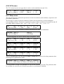
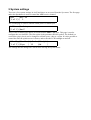
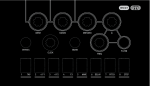
1
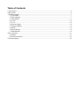
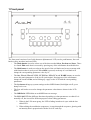
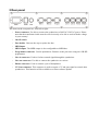
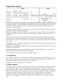
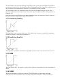
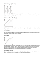
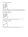
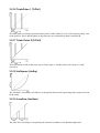
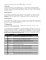
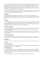
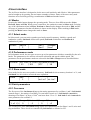
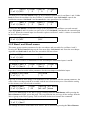
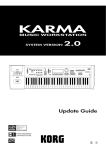
user manual
This is a pre-release version of the AvrX user
manual. Some of the contents may change in the
official version, and there might be some errors.
Some of the contents, like the MIDI specification
will be added at a later point.
If you find any errors in this text, please post a
message on our web forum on www.avrx.se/forum.
We would also like to know if there is something
that needs to be explained better.
Table of Contents
1 Front panel.........................................................................................................................................4
2 Rear panel.......................................................................................................................................... 6
3 Synthesis engine................................................................................................................................ 7
3.1 Oscillators.................................................................................................................................. 7
3.2 Waveshapers.............................................................................................................................. 7
3.3 Wavetables...............................................................................................................................13
3.4 VCFs........................................................................................................................................ 14
3.5 VCA......................................................................................................................................... 14
3.6 External input...........................................................................................................................14
3.7 Ring modulator........................................................................................................................ 14
3.8 Noise........................................................................................................................................ 14
3.9 Bit reduction............................................................................................................................ 14
3.10 Modulation.............................................................................................................................14
4 User interface...................................................................................................................................16
4.1 Modes.......................................................................................................................................16
4.2 Patch parameters...................................................................................................................... 16
5 System settings................................................................................................................................ 20
1 Front panel
The front panel consists of one 2x40 character alphanumeric LCD, twelve push buttons, four soft
knobs (rotary encoders) and two LEDs.
•
The Mode button is used to select one of the three modes Select, Perform and Store. There
is a fourth Edit mode that is accessed by pressing any of the edit buttons described below.
•
The Shift button is used to accelerate the speed of the soft knobs and to access menus with
with functions that is rarely used. When Shift is pressed, each step of a soft knob will
change the corresponding parameter value by 10.
•
The Osc, Wave1, Wave2, VCF1, VCF2, Env, LFO, VCA and WARP buttons are used to
access the patch parameters of the AvrX synth engine. Pressing one of the edit buttons
change the mode to Edit, and will bring up a page on the LCD with the corresponding
parameters.
•
The Sys button brings up system settings such as MIDI channel, backlight on/off, sysex
dump receive etc.
•
The four soft knobs are used to change the parameter value that are shown in the LCD
above.
•
The MIDI/Alt1 LED blinks at each MIDI note on message.
•
The LFO/Alt2 LED has different functions depending on what parameters are edited. It is
normally off, but is used for different purposes when editing parameters.
1. When in the LFO menu group, the LED is fading in and out in sync with the last
edited LFO.
2. When editing the modulation sequencers, it steps through the sequence, glowing with
an intensity that is proportional with the level of each step.
3. When the external input is activated and the LFOs or sequencers are not being edited,
the LFO/Alt2 LED indicates clipping on the external input.
2 Rear panel
The items on the rear panel are, from left to right:
•
Power connector. Use this to connect the synthesizer to 240VAC/120VAC power. Please
note that the transformer inside must be wired correctly to be able to work with the voltage
in your country!
•
On/off switch.
•
Fuse holder. Unscrew the cap to replace the fuse.
•
MIDI input.
•
MIDI output. The MIDI output is also configurable as MIDI thru.
•
Programmer connector. Used to upload new firmware to the processor using an AVR-ISP
programmer.
•
Line in connector. Used to feed an external signal through the synthesizer.
•
Line out connector. Use this to connect the synthesizer to a mixer.
•
Phones connector. Used to connect a pair of headphones.
•
CV/Gate connector. This connector is used to output a CV and gate signal to control other
synthesizers. This function will be available as a future software update.
3 Synthesis engine
The picture above shows a block diagram of the synthesis engine. The sound generation starts with
two digital oscillators. Each oscillator has a modulation input for pitch modulation and the second
oscillator can be synchronized to the first oscillator. The second oscillator can be replaced by a
signal from the external input.
The signals from the oscillators are fed to two waveshapers (WS1 and WS2) with two modulation
inputs and a number of different algorithms.
After the waveshapers, the signals comes to two wavetable generators (WT1 and WT2), each with a
modulation input that are used to select the waveform that are used from a list of 256 different
waveforms.
Although it is not shown in the block diagram, the waveshapers can be placed after the wavetable
generators. If a waveshaper is placed before a wavetable, it affects the phase angle that scans the
waveform during a cycle. If it is placed after the wavetable, it affects the amplitude of the waveform
over a cycle.
The signals from the oscillators/waveshapers/wavetables are then mixed with the signals from a ring
modulator and a noise source.
After the mixer, the signal is manipulated by a bit reduction unit, just before the signal is converted
to analog by the audio DAC.
The signal is then fed to two analog multimode filters (LP, BP and HP) that can be connected in
serial or parallel. Each filter has two modulation inputs.
Last in the chain is the VCA, also with two modulation inputs.
3.1 Oscillators
There are two oscillators in AvrX. Each has a modulation input with a maximum range of ±16 semi
notes. Each semi note of range corresponds to 16 steps of the level parameter, so setting the level
parameter for a modulator to 192 sets the range to one octave.
Oscillator 2 can also be synchronized to oscillator 1.
3.2 Waveshapers
The outputs from the oscillators are fed to two waveshapers. A waveshaper is a function that based
on the momentary values of the input signal and it is two modulators calculates an output value.
Because the output value from the oscillators are proportional to the waveforms phase value this is
useful to affect the shape of the waveform. There are a number of algorithms for the waveshapers to
use that all affect the waveform in different ways. Some of the waveshapers are best used in
combination with the wavetable generator. By placing a waveshaper before a wavetable, it is
possible to scan through the waveform in different ways, and affecting it is shape in interesting
ways.
The waveshapers may introduce aliasing. Depending on how you use the waveshaper, the problem
may be more or less severe. The problem increases with higher pitch, so it may be a good idea not to
use waveshapers for sounds that are meant to be played high up in the keyboard.
The waveshapers have two modulation inputs each, and both modulation inputs have an offset
parameter and an amount parameter. The value of the sum of modulator and the offset parameter is
limited to 255.
In the descriptions of the different waveshaper algorithms below, the input waveform is shown as a
gray line (always a ramp) and the output as a black line.
3.2.1 SawInvert (SawInv)
This algorithm inverts a section of the wave. The width of the section are controlled by modulator
B, and the position is controlled by modulator A.
3.2.2 SawPulse (SawPls)
This algorithm is similar to the SawInvert algorithm, but the section is not inverted, but set to 255.
3.2.3 PWM
The usual PWM effect. The output is a pulse whose width are controlled by the sum of modulator A
and B.
3.2.4 PWM2
This PWM algorithm is a little more elaborate. The PWM effect is generated by taking the
difference of a waveform and the same waveform with a phase difference. If this waveshaper is
applied on a sawtooth waveform, the result would be normal PWM, but any waveform can be used.
One advantage of this algorithm over the other PWM algorithm is that the result does not contain
any overtones not present in the original waveform, so it is easier to keep the sound alias free. The
waveform is selected by modulation input B, and the PWM effect is controlled by modulation input
A. Since this waveshaper in itself plays waveforms from the wave memory, there is no need to use
the normal wavetable generator. If waveform 0 is selected, the wavetable does not affect the sound.
(Of course any waveform can be selected there. This waveform would introduce a kind of distortion
that might sound interesting)
3.2.5 Stairs
The signal is divided into four steps. The first one always has the value 0 and the last is always 255.
The second and third step is controlled by modulator A and B respectively.
3.2.6 Slopes
This algorithm is similar to the Stairs-waveshaper, but the different segments are instead sloping.
3.2.7 Compressor (Cmprs)
The compress algorithm is used to lower the amplitude of the signal. When used before a wavetable,
it will scan through just the middle parts of the waveform.
3.2.8 SimSync (SimSnc)
Simulated oscillator sync. Modulator A multiplies the frequency of the waveform, but the wave is
always restarted at the beginning of the cycle, so the overtone content is always harmonic, and the
fundamental is always the same.
3.2.9 SawWrap (SawWrp)
Modulator A puts an offset on the wave, and lets it “wrap” over the top where the value exceeds
255. Applied before a wavetable generator, this means the waveform will be scanned forward before
this point, and backwards after.
3.2.10 XOR
The input signal is XORed with the value of modulator B. Modulator A is used to control the mix
between the original and the XORed waveform.
3.2.11 PD1
This phase distortion algorithm increases the slope at the first half of the waveform and decreases it
at the second half, creating a “knee”. This is very useful for adding overtones to a dull waveform,
and when swept it can create very interesting results. Modulator A controls the slope, and
Modulator B shifts the phase of the entire waveform from 0 to 360 degrees.
3.2.12 PD2 to PD5
The rest of the phase distortion algorithms, PD2, PD3, PD4 and PD5, are similar to PD1, but the
“knee” is located at 1/4, 1/8, 1/16 and 1/32 of the waveform respectively.
3.2.13 Dementor 1 (Demnt1)
The first dementor waveshaper creates an oscillator sync kind of sound by bringing in an increasing
number of pulses when applying a modulator to modulation inputs A and B. Both modulation inputs
affects individual sets of pulses. The bottom of the pulses are shaped as a ramp with a slope that
increases with Mod A and Mod B.
3.2.14 Dementor 2 (Demnt2)
The second dementor waveshaper works in the same way as the first, but there is only one set of
pulses that is affected by Mod A. Mod B controls the slope of the ramp.
3.2.15 Dementor 3 (Demnt3)
The third dementor waveshaper creates a set of pulses that stretches from the input ramp level to
another level that is set by Mod B. Again, Mod A controls the amount of pulses.
3.2.16 TriplePulse 1 (TrPls1)
The triple pulse waveshaper generates three pulses with a width of 1/16th of the total waveform. One
of the pulses is fixed, and the phase of the other two are controlled by Mod A and Mod B.
3.2.17 Triple Pulse 2 (TrPls2)
This waveshaper works in the same way as Triple pulse 1, but the pulses move atop of a ramp
waveform.
3.2.18 LinSquare (LinSqr)
The LinSquare waveshaper uses Mod A to interpolate between the input ramp and a squared version
of the ramp.
3.2.19 JunoSaw (JunSaw)
The Juno Saw waveshaper is inspired by the sawtooth oscillator in the Roland Alpha Juno
synthesizers. Mod A introduces a kind of PWM to the input ramp signal.
3.2.20 Hal
This is kind of an odd waveshaper in that it lets you use any waveform to scan through another
waveform. The waveform to be scanned through is selected the normal way. Modulation input B
selects the scanning waveform and modulation input A controls how far into the first waveform the
second one will scan.
3.2.21 Smooth
This waveshaper is similar to the Hal waveshaper, but modulation input A is used to cross fade
between the arbitrary waveform and linear scanning. A low modulation value will scan the first
waveform linearly while a higher value will introduce the non linear scanning of the second
waveform.
3.2.22 Volume
This waveshaper simply changes the volume of the input signal. It should normally be placed after
the wavetable to allow independent volume control of the oscillators outputs, but can also be used in
front of the wavetable for more unusual effects.
3.3 Wavetables
The waveforms in AvrX are organized in 16 banks of 16 waveforms each. Each wave is 256
samples long, and the resolution is 8 bits.
The waveforms contains different numbers of overtones. That means that many waveforms will
generate aliasing when played high up on the keyboard. To avoid aliasing, choose a waveform that
sounds good in the frequency range you intend to play the sound. Bank 2 and 3 contains sawtooth
and square waves with a decreasing number of overtones to allow the user to choose a waveform
that is alias free. It is also possible to automate the waveform choice by assigning the Osc1Frq or
Osc2Frq modulators to the waveform selection input.
Bank Name
Description
1
Simple waves
Different types of saw, square, sine and triangle waves
2
Sawtooth
Sawtooth waves with decreasing number of overtones
3
Square
Square waves with decreasing number of overtones
4
Noise
Different “noisy” waves with different duty cycles
5
Resonance 1
Resonant waveforms with increasing resonance frequency
6
Resonance 2
Resonant waveforms with increasing resonance frequency
7
Voice 1
Different male vocal sounds
8
Voice 2
Different female vocal sounds
9
FM1
FM waveforms with decreasing amount of modulation
10
FM2
FM waveforms with decreasing amount of modulation
11
FM3
FM waveforms with decreasing amount of modulation
12
FM4
FM waveforms with decreasing amount of modulation
15
Bell
Bell waveforms with decreasing number of overtones
16
Sines
Waveforms generated from mixtures of sine waves to the 5th harmonic
13
14
Each wavetable generator has three parameters: Start wave, Modulator and Modulation amount. To
use a single waveform, set Start wave to that waveform, and set Modulation amount to 0. To scan
through an entire bank of waveforms, set the start wave to the first wave in that bank, choose an
appropriate modulator, and set modulation amount to 15. If modulation amount is set to a value
higher than 15, the modulator will scan through more than a single bank. A value of 255 makes the
modulator scan through the entire waveform memory.
It is also possible to use the program area of the flash memory instead of the waveform area. This is
useful to create very harsh sounds. The “waveforms” in this area are really the AvrX software, so
new versions of the software will sound different!
3.4 VCFs
There are two independent analog multimode filters in AvrX. The filters has lowpass (LP),
bandpass (BP) and highpass (HP) outputs. The signal can be routed through the filters in both serial
and parallel. There are parameters for cutoff and resonance, and two modulation inputs for each
filter.
3.5 VCA
Last in the signal chain is the voltage controlled amplifier (VCA). It has two modulation inputs that
work according to the formula: ModA · ModAAmt + ModA · ModB · ModBAmt. The reason to
multiply modulator B with modulator A is to make it possible to make for example an envelope to
totally mute the VCA and still use an LFO as a second modulator.
3.6 External input
The external input replaces oscillator 2 in the signal chain when activated. This means that you can
route the signal through the waveshaper, the wavetable, bit reduction and filters exactly as you
would with oscillator 2.
Since there is no gain knob for the external input, the input level must be set externally. When the
external input is activated, the LFO/Alt2 LED indicates clipping. When the signal is to hot, the led
will start blinking.
3.7 Ring modulator
The ring modulator multiplies the signals after wavetable 1 and wavetable 2 (or waveshaper 1/2 if
they are placed after the wavetables). The level of the sing modulators output is set in the mixer.
3.8 Noise
The noise source can be used both as a sound source if the level is turned up in the mixer, and as a
modulator.
3.9 Bit reduction
The bit reduction is placed last in the audio chain just before the signal leaves the digital domain.
Each bit can be turned on or off individually.
3.10 Modulation
The modulation scheme of AvrX is straight forward. There are a number of different modulation
sources such as envelopes LFOs etc. Everything that can be modulated has one or two modulation
inputs. When assigning a modulator to a modulation input it is just a matter of selecting the right
modulator from a list.
Each modulation input has an associated amount parameter and an offset parameter.
3.10.1 Envelopes
The three envelope generators are of ADSR type, with Attack, Decay, Sustain and Release
parameters. The attack time can be varied from 0.25ms to 16 seconds. The Decay and Release times
can vary from 64ms to 16 seconds. Each envelope generator has two outputs. One normal and one
inverted.
3.10.2 LFOs
There are three LFOs in AvrX. Each has a rate parameter, a trig parameter and five different
waveform outputs. The available waveforms are: Square, Triangle, Positive Saw, Negative Saw and
Sample and hold. The rate parameter controls the rate of the LFO from 0.06Hz to 4kHz. The trig
parameter can have five different values. If off, the LFO is free running. If on, the LFO is restarted
at note on. The LFOs can also be trigged by MIDI clock at the rate of 1/4th, 1/8th, an 1/16th note.
LFO1 is a little different from the others. It has a modulation input to control its rate, and there is a
modulation input to the sample and hold function, allowing it to sample any modulator. LFO2 and
LFO3 only samples noise.
3.10.3 Sequencers
There are two sequencers that lets the user create 8-step sequences. Both sequencers share the same
rate parameter, so the tempos will always be the same. The tempo can be varied from 64ms per step
to 16 seconds per step. There is also a trig parameter. When set to off, the sequencers are free
running. When on, the sequences restart at note on. There is also a MIDI tempo sync feature. When
trig is set to 4th, 8th, or 16th, the sequencers will be synchronized to MIDI clock. When the tempo is
synchronized, the sequencers will start over when a key is pressed.
3.10.4 Mod combiner
The mod combiner takes two modulation inputs and outputs the product of those. This is useful
when you want to control the amount of modulation with another modulator. If you for example
want to use an LFO to create a vibrato that fades in gradually, you can use the mod combiner to led
an envelope control the amount of the LFO.
3.10.5 Key random
The Key random modulator samples the noise source each time a key is pressed. This value is then
held until another key is pressed. This is useful to randomize parameters like filter cutoff or
wavetable waveform.
3.10.6 Other modulators
There are some more modulators available:
•
Oscillator 1
•
Oscillator 2
•
Noise
•
MIDI velocity
•
MIDI pitch bend
•
MIDI modulation wheel
•
MIDI note
•
Oscillator 1/2 frequency
4 User interface
The AvrX user interface is designed to let the user work intuitively and effective. Most parameters
can be brought up by pressing just one button a number of times. Some of the more rarely used
functions are accessed by pressing a combination of Shift and another button.
4.1 Modes
Pressing the Mode button changes the operating mode. There are four different modes: Select,
Preform, Store and Edit. When power is turned on, the synthesizer starts in Select mode. Pressing
any of the edit buttons when in Select, Perform or Store modes changes the mode to Edit, and the
first page of parameters for that edit button is shown on the display. When working in Edit mode,
pressing the Mode button changes the mode to Store.
4.1.1 Select mode
In Select mode, you can retrieve patches previously stored in memory, initialize a patch, and
randomize a patch. Soft knob 1 selects the patch, Soft knob 3 initializes and Soft knob 4
randomizes a patch.
Select
|Patch
| 1
|
|
|Init
|Run?
|Random
|Run?
4.1.2 Performance mode
In Performance mode, the user gets access to up to four parameters which are controlled by the soft
knobs. The parameters to be used are selected in edit mode and stored with the patch. The
parameters for the performance mode are selected in the Shift + Warp menu as described below.
Perform |VCF1Cut|VCF1Res|VF1MdAA|W1Start
| 25
|101
|177
| 18
4.1.3 Store mode
Store mode lets the user store patches in memory. Soft knob 1 selects memory location 1 to 31, and
Soft knob 3 or 4 is used to execute the store operation.
Store
|Pos
| 1
|
|
|
|
|Write? |Write?
4.2 Patch parameters
4.2.1 Osc menu
The first press of the Osc button brings up the tuning parameters for oscillator 1 and 2. Soft knob 1
controls range 1, the tuning of oscillator 1 in semi notes from 0 to 63. Soft knob 2 controls the
detuning of oscillator 1 in steps of 1/64th semi note from -32 to +31. Soft knob 3 and 4 controls the
same parameters for oscillator 2.
Osc
|Range 1|Detune1|Range 2|Detune2
(1 of 4)| 0
| -2
| 0
| +3
The second press of the Osc button brings up the level parameters for Oscillator 1 and 2, noise and
ring modulation. Those levels are controlled by Soft knob 1 to 4 from 0 to 255.
Osc
|Level 1|Level 2|Noise
(2 of 4)|255
| 0
| 0
|Ringmod
| 0
The third press of the Osc button brings up the modulation parameters for oscillator 1 and 2. Soft
knob 1 selects the modulator for the oscillator 2's modulation input. Soft knob 2 controls the
modulation amount. Soft knob 3 and 4 controls the same parameters for oscillator 2.
Osc
|Mod 1
(3 of 4)|Env1
|Level 1|Mod 2
| 0
|Env1
|Level 2
| 0
Pressing the Osc button a fourth time brings up the parameters for oscillator sync and external
input. Soft knob 1 and 2 is used to set sync to on or off. Soft knob 3 and 4 turns the external input
on or off. When the external input is activated it replaces oscillator 2, and it´s volume is controlled
by the Osc2 level parameter.
Osc
|Sync
(4 of 4)|OFF
|Ext in
|OFF
4.2.2 Wave1 and Wave2 menus
This menu group contains parameters for the waveshaper and wavetable for oscillator 1 and 2.
Pressing the Wave1 button brings up the first menu page. Soft knob 1 and 2 sets the waveshaper
algorithm and Soft knob 3 and 4 sets the wavetable start waveform.
W-shape1|Type
(1 of 4)|OFF
|Start
| 12
The next page is used to set modulators for the waveshapers modulation inputs A and B.
W-shape1|Mod A
(2 of 4)|Env1
|Level A|Mod B
| 0
|Env1
|Level B
| 0
Page three is used to set the offset parameters for the waveshapers modulation inputs.
W-shape1|OffsetA
(3 of 4)| 0
|OffsetB
| 0
Page four is used for three things. The modulator for the wavetable with the amount parameter, the
order of the waveshaper and the wavetable, and the waveform memory area. Note that the setting
for the memory area affects both wavetables.
W-table1|Mod
(4 of 4)|Env3
|Level
| 49
|Config |WT area
|WS->WT |Wave
There is one hidden page in the Wave1 group. Holding down the Shift button while pressing the
Wave1 button will take you to this page. The copy function lets you copy all the settings from the
Wave1 group to the Wave2 group. Turn a soft knob clockwise to execute the command.
W-table1|Copy1>2
(1 of 1)|Run?
The settings for Wave2 is the same as for Wave1, but is accessed by pressing the Wave2 button.
4.2.3 VCF1 and VCF2 menus
The VCF1 menu group controls all the parameters for VCF1. The first is used to set the cutoff and
resonance parameters, as well as the filter type (LP, BP, HP) and the filter configuration
(parallel/serial). There is also a third configuration called 24dB, that sets both filters in serial mode
and links all parameters from VCF1 to VCF2 to create one steeper filter from the two two pole
filters. If the filters are in 24dB mode, pressing the VCF2 button will exit the mode and set the
filters in individual modes again.
VCF 1
|Cutoff |Res
(1 of 2)|255
| 0
|Type
|LP
|Config
|serial
Page two sets the modulators for VCF1s 2 modulation inputs.
VCF 1
|Mod A
(2 of 2)|Env2
|Level A|Mod B |Level B
|205
|LFO1Tri| 0
There is a hidden page (Shift + Wave1) that is used to copy all the parameters for VCF1 to VCF2 in
the same way as for Wave1 and Wave2.
VCF 1
|Copy1>2
(1 of 1)|Run?
The settings for VCF2 is the same as for VCF1 except that the filters can not be set in 24dB mode
from the VCF2 menu.
4.2.4 Env menu
The Env menu group contains three pages that are used to control the three ADSR envelope
generators. Each soft knob controls one of the Attack, Decay, Sustain and Release parameters.
Env 1
|Attack |Decay
(1 of 3)| 0
|249
|Sustain|Release
|255
|245
4.2.5 LFO menu
This menu group is used to control the LFO settings. The first page contains the rate parameters for
the three LFOs and the modulation sequencers.
LFO
|Rate 1 |Rate 2 |Rate 3 |SeqRate
(1 of 3)| 10
| 20
| 30
| 40
The next page contains the retrig parameters. For each LFO, this parameter can be set to OFF, ON
(retrig at keypress) and 4th, 8th, and 16th (retrig by keypress and MIDI clock)
LFO
|Trig 1 |Trig 2 |Trig 3 |SeqTrig
(2 of 3)|OFF
|ON
|8th
|16th
Page three contains the modulation and S&H input for LFO1.
LFO
|Mod
(3 of 3)|Env1
|Level
| 0
|SH Mod |
|Noise |
4.2.6 VCA menu
The VCA menu has only one page that is used to set the modulators for the VCA.
VCF 1
|Mod A
(1 of 1)|Env1
|Level A|Mod B
|255
|Env1
|Level B
| 0
4.2.7 Warp menu
The warp menu group contains the parameters for the bit reduction, mod combiner, sequencers and
performance parameters.
The first page is used to set the bit reduction. Each bit can be turned on or off by rotating the
corresponding soft knob. The bits are organized in groups of three and the bits are turned on and off
in a simple binary sequence: 000 → 001 → 010 → 011 → 100 → 101 → 110 → 111.
Bit
|11 - 9 |8 – 6
(1 of 6)|111
|111
|5 - 3
|111
|2 – 0
|111
Page two is used for the modulation combiner and shows two inputs for modulators.
ModComb |Mod A
(2 of 6)|Env1
|Mod B
|LFO2Sqr
The following pages are used to edit the steps of sequencer 1 and 2.
Seq 1
|Pos 1
(3 of 6)| 60
|Pos 2
| 30
|Pos 3
| 0
|Pos 4
|255
Seq 1
|Pos 5
(4 of 6)| 0
|Pos 6
|255
|Pos 7
| 0
|Pos 8
|255
Seq 2
|Pos 1
(5 of 6)|255
|Pos 2
| 0
|Pos 3
| 0
|Pos 4
| 22
Seq 2
|Pos 5
(6 of 6)| 26
|Pos 6
| 17
|Pos 7
| 0
|Pos 8
| 0
There is a hidden page in the Warp group (Shift + Warp) that is used to select the parameters that
should appear in performance mode.
Perform |Pos 1 |Pos 2 |Pos 3 |Pos 4
(1 of 1)|VCF1Cut|VCF1Res|LFO1Rat|No func
It is not possible to assign every parameter in AvrX to the performance mode. The parameters that
are available are selected to be as useful as possible in a performance situation.
5 System settings
There are a few system settings in AvrX and those are accessed from the Sys menu. The first page
under the Sys-button is used to control the MIDI receive channel.
MIDI
|Rcv CH
(1 of 2)| 1
The second page is used to send the edited patch via MIDI sysex.
SYSEX
|Snd tmp
(2 of 2)|Run?
There is also a hidden page that is accessed from the Shift + Sys keys. This page is used to
configure the user interface. The first option is the parameter divider symbol. The default is a
vertical bar (pipe), but it can be changed to a blank space, a dot or a colon. It is also possible to
control the time the splash screen is shown, and to turn the LCD backlight on and off.
UIConfig|Divider|Splash |BkLight|
(1 of 1)|Pipe
| 11
|ON
|
The settings that are changed are stored when leaving the System menu.