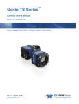
1
Piranha4 Color P4-CC-08K050-00-R Camera User’s Manual 03 August 2012 03-032-20156-00 www.teledynedalsa.com 2 Piranha4 8K Camera Color User's Manual © 2012 Teledyne DALSA, Inc. All information provided in this manual is believed to be accurate and reliable. No responsibility is assumed by Teledyne DALSA for its use. Teledyne DALSA reserves the right to make changes to this information without notice. Reproduction of this manual in whole or in part, by any means, is prohibited without prior permission having been obtained from Teledyne DALSA. About Teledyne Technologies and Teledyne DALSA, Inc. Teledyne Technologies is a leading provider of sophisticated electronic subsystems, instrumentation and communication products, engineered systems, aerospace engines, and energy and power generation systems. Teledyne Technologies‘ operations are primarily located in the United States, the United Kingdom and Mexico. For more information, visit Teledyne Technologies‘ website at www.teledyne.com. Teledyne DALSA, a Teledyne Technologies company, is an international leader in high performance digital imaging and semiconductors with approximately 1,000 employees worldwide, headquartered in Waterloo, Ontario, Canada. Established in 1980, the company designs, develops, manufactures and markets digital imaging products and solutions, in addition to providing MEMS products and services. For more information, visit Teledyne DALSA‘s website at www.teledynedalsa.com. Support For further information not included in this manual, or for information on Teledyne DALSA‘s extensive line of image sensing products, please contact: North America Europe Asia Pacific 700 Technology Park Drive Billerica, MA USA, 01821 Tel: 978-670-2000 Fax: 978-670-2010 Email: [email protected] Felix-Wankel-Str. 1 82152 Krailling Germany Tel: +49 89 89 54 57 3-80 Fax: +49 89 89 54 57 3-46 Email: [email protected] Ikebukuro East 13F 3-4-3 Higashi Ikebukuro, Toshima-ku, Tokyo Japan Tel: +81 3 5960 6353 Fax: +81 3 5960 6354 Email: [email protected] 03-032-20156-00 Teledyne DALSA Piranha4 8K Color Camera User's Manual 3 Contents System Precautions ............................................................................................................................................................ 5 Precautions ..................................................................................................................................................... 5 Electrostatic Discharge and the CMOS Sensor ................................................................................................. 5 2. The Piranha4 Color Camera _______________________________________________________________________ 6 Camera Highlights ............................................................................................................................................................. 6 Camera Performance Specifications .................................................................................................................................. 7 Certifications ...................................................................................................................................................................... 8 Supported Industry Standards ........................................................................................................................................... 8 Responsivity ....................................................................................................................................................................... 9 FPN Characteristics with Temperature .............................................................................................................................. 9 Sensor Shift Direction Example ...................................................................................................................... 10 Mechanicals........................................................................................................................................................................ 11 Camera Mounting and Heat Sink Considerations ........................................................................................... 12 3. Quick, Simple Steps to Acquire an Image ______________________________________________________________ 13 4. Software and Hardware Setup______________________________________________________________________ 14 Recommended System Requirements ............................................................................................................. 14 Setup Steps: Overview ....................................................................................................................................................... 14 1. Install and Configure Frame Grabber and Software (including GUI) ........................................................ 14 2. Connect Camera Link and Power Cables .................................................................................................... 14 3. Establish communicating with the camera.................................................................................................. 14 4. Operate the Camera ................................................................................................................................... 14 Step 1. Install and configure the frame grabber, and software (including GUI) .............................................................. 15 Install Frame Grabber .................................................................................................................................... 15 Install Sapera LT and CamExpert GUI ............................................................................................................ 15 Step 2. Connect Data, Trigger, and Power Cables ............................................................................................................. 16 Data Connector: Camera Link ........................................................................................................................ 16 Camera Link Bit Definitions............................................................................................................................ 18 RGB 8 bit CL Deca, max line rate 34 kHz without AOI and 85MHz CL clock .................................................. 20 Custom AOI Rules............................................................................................................................................ 23 Camera Link cable quality and length............................................................................................................ 24 Input Signals, Camera Link ............................................................................................................................ 24 Output Signals, Camera Link Clocking Signals............................................................................................... 25 Power Connector ............................................................................................................................................. 25 LEDs ................................................................................................................................................................ 26 Step 3. Establish Communication with the Camera ........................................................................................................... 26 Power on the camera ...................................................................................................................................... 26 Connect to the frame grabber ......................................................................................................................... 26 Connect to the camera .................................................................................................................................... 26 Check LED Status ............................................................................................................................................ 27 Software Interface ........................................................................................................................................... 27 Using Sapera CamExpert with Piranha4 Cameras ............................................................................................................ 28 CamExpert Panes ............................................................................................................................................ 29 Teledyne DALSA 03-032-20156-00 4 Piranha4 8K Camera Color User's Manual Review a Test Image ....................................................................................................................................... 31 4. Camera Operation______________________________________________________________________________ 32 Factory Settings ................................................................................................................................................................. 32 Check Camera and Sensor Information ............................................................................................................................. 32 Verify Temperature and Voltage ....................................................................................................................................... 33 Saving and Restoring Camera Settings ............................................................................................................................. 33 Camera Link Configuration ............................................................................................................................................... 35 Trigger Modes .................................................................................................................................................................... 35 Exposure Controls .............................................................................................................................................................. 35 Exposure Modes in Detail .................................................................................................................................................. 36 Set Line Rate ..................................................................................................................................................................... 39 Set Exposure Time ............................................................................................................................................................. 39 Control Gain and Black Level ............................................................................................................................................ 40 Set Image Size ................................................................................................................................................................... 40 Set Baud Rate .................................................................................................................................................................... 40 Pixel Format ...................................................................................................................................................................... 41 Camera Direction Control .................................................................................................................................................. 41 Pixel Readout Direction (Mirroring Mode) ........................................................................................................................ 42 Resetting the Camera ........................................................................................................................................................ 42 Calibrating the Camera ..................................................................................................................................................... 43 Appendix A: GenICam Commands _____________________________________________________________________ 47 DeviceInformation “Camera Information” Group .......................................................................................... 47 deviceSensorControl “Camera Control” Group ............................................................................................... 51 ImageFormatControl “Image Format” Group ................................................................................................ 55 FileAccessControl “File Access Control” Group ................................................................................................ 57 serialPortControl ”Serial Port” Group ............................................................................................................ 57 dataProcessing “Flat Field” Group ................................................................................................................. 58 TransportLayerControl “Transport Layer” Group ........................................................................................... 61 Appendix B: ASCII Commands _______________________________________________________________________ 62 Port Configuration .......................................................................................................................................... 62 Commands ...................................................................................................................................................... 63 Appendix C: Quick Setup and Image Acquisition ___________________________________________________________ 72 Appendix D: The Sensor Window _____________________________________________________________________ 75 Cleaning and Protecting Against Dust, Oil, and Scratches.............................................................................. 75 Cleaning the Sensor Window .......................................................................................................................... 76 EMC Declaration _________________________________________________________________________________ 77 Revision History _________________________________________________________________________________ 78 Index ________________________________________________________________________________________ 79 03-032-20156-00 Teledyne DALSA Piranha4 8K Color Camera User's Manual 5 System Precautions Precautions Read these precautions and this manual carefully before using the camera. Confirm that the camera‘s packaging is undamaged before opening it. If the packaging is damaged please contact the related logistics personnel. Do not open the housing of the camera. The warranty is voided if the housing is opened. Keep the camera housing temperature in a range of 0 °C to 50 °C during operation. Do not operate the camera in the vicinity of strong electromagnetic fields. In addition, avoid electrostatic charging, violent vibration, and excess moisture. To clean the device, avoid electrostatic charging by using a dry, clean absorbent cotton cloth dampened with a small quantity of pure alcohol. Do not use methylated alcohol. To clean the surface of the camera housing, use a soft, dry cloth. To remove severe stains use a soft cloth dampened with a small quantity of neutral detergent and then wipe dry. Do not use volatile solvents such as benzene and thinners, as they can damage the surface finish. Further cleaning instructions are below. Though this camera supports hot plugging, it is recommended that you power down and disconnect power to the camera before you add or replace system components. Electrostatic Discharge and the CMOS Sensor Image sensors and the camera bodies housing are susceptible to damage from electrostatic discharge (ESD). Electrostatic charge introduced to the sensor window surface can induce charge buildup on the underside of the window that cannot be readily dissipated by the dry nitrogen gas in the sensor package cavity. The charge normally dissipates within 24 hours and the sensor returns to normal operation. Additional information on cleaning the sensor window and protecting it against dust, oil, blemishes, and scratches can be found here, Appendix D: Sensor Window: Cleaning and Protecting Against Dust, Oil, and Scratches. Teledyne DALSA 03-032-20156-00 6 Piranha4 8K Camera Color User's Manual 1. The Piranha4 Color Camera Camera Highlights Based on Teledyne DALSA's unique CMOS color line scan sensor architecture, the new Piranha4 8k bilinear color camera provides outstanding signal-to-noise for high speed imaging. The P4-8k has 8k resolution with a 7 µm x 7 µm pixel size for optimized optical design. The camera delivers a max line rate of 50 kHz in a high responsivity summing mode. Precise sensor alignment simplifies multiple camera calibration at the system level. GenICam™ or ASCII command-compliant interfaces make the camera easier to setup, control, and integrate. Programmability includes exposure control, flat field correction, and gain settings. The Piranha4 8k camera is ideal for printing inspection, printed circuit board, solar cell, film, and large format web inspection. Key Features CMOS color bilinear line scan 8k pixel resolution Line rates up to 50 kHz Exposure control 100x antiblooming RGB, RG / BG, or G outputs Camera Link interface GenICam or ASCII command-compliant interfaces Programmability Save up to eight sets of correction coefficients Adjustable gain and offset White balance and color correction Lens and shading correction with defocusing cap ability Test pattern and diagnostics Multi-AOI output allows faster line rates Applications Printing inspection High performance document scanning Electronics Film inspection High throughput applications 03-032-20156-00 Teledyne DALSA Piranha4 8K Color Camera User's Manual 7 Models The camera is available in the following configurations: Table 1: Camera Models Overview Model Number P4-CC-08K050-00-R Description 8k resolution, 50 kHz line rate, Camera Link interface. Table 2: Software Software Camera firmware GenICam™ support (XML camera description file) Sapera LT, including CamExpert GUI application and GenICam for Camera Link imaging driver Product Number / Version Number Embedded within camera Embedded within camera Version 7.2 or later Camera Performance Specifications Table 3: Camera Performance Specifications Specifications Performance Imager Format CMOS bilinear color line scan Resolution 8192 x 2 pixel lines: 8192 x 1 pixel line Green, and 8192 x 1 pixel line alternating Red-Blue Pixel Size 7.04 µm x 7.04 µm Full Well Capacity 20k e- @ minimum gain of 1x Line Rate 0 kHz minimum to 50 kHz maximum (Deca RGBG8), 34 kHz maximum (Deca RGB8), 20 kHz maximum (Medium), 10 kHz maximum (Base RGB8) Exposure Time 11 µs minimum to 3,000 µs maximum Bit Depth 8 bits Connectors and Mechanicals Control & Data Interface Base, Medium, or Deca* Camera Link configurations—MDR26 Power Connector Hirose 6-pin circular Power Supply + 12 V to + 24 V DC Maximum Current Draw 17W/ (Applied voltage at camera connector) Power Dissipation 17 W Size 80 mm (W) x 130 mm (H) x 57 mm (D) Without heat sinks: 80 mm (W) x 80 mm (H) x 57 mm (D) Mass < 700 g, including heat sinks (< 530 g without heat sinks) Operating Temp 0 °C to 50 °C, front plate temperature Optical Interface Lens Mount M72 x 0.75, F-mount** Sensor to Camera Front Distance 12 mm Sensor Alignment (aligned to sides of camera) Flatness y (parallelism) x y z z Teledyne DALSA 50 µm 0.08° or 81 µm ± 50 µm ± 50 µm ± 250 µm ± 0.2° 03-032-20156-00 8 Piranha4 8K Camera Color User's Manual Compliance Regulatory Compliance CE and RoHS; GenICam *At the time of this release, CamExpert does not accommodate color Deca 9.1 mode. Contact Customer Support if you are interested in evaluating a camera using this mode. ** F-mount lenses are optimized for a maximum image circle of 43.2 mm. However, the P4-8k sensor is 57.67mm long. Using an F-mount lens will generate a good image for the center 6008 pixels. However pixels beyond this range may suffer from optical distortion caused by the lens. If an application requires the use of an F-mount lens with P4-8K cameras, contact Customer Support for additional details regarding the use of F-mount lenses and for access to a suitable F-mount-to-M72 adapter. Operating Ranges Performance Green Red Blue Dynamic Range 62.5 dB 62.5 dB 62.5 dB Random Noise 0.186 DN** rms 0.186 DN** rms 0.186 DN** rms Broadband Responsivity 3.2 DN/(nJ/cm2) 4.4 DN/(nJ/cm2) 2.2 DN/(nJ/cm2) Gain 1x to 10x Nominal Range (not including individual RGB gains for white balance) DC Offset <1 DN <1 DN <1 DN PRNU <2% @50% Sat <2% @50% Sat <2% @50% Sat FPN < 3 DN < 3 DN < 3 DN SEE 78 nJ / cm2 56 nJ / cm2 113 nJ / cm2 NEE 58 pJ / cm2 42 pJ / cm2 84 pJ / cm2 Antiblooming > 100 x Saturation Integral non-linearity < 2% DN **DN = digital number Test Conditions: Values measured using 8-bit, 1x gain. 10 kHz line rate Light source: white LED No white balancing Front plate temperature: 45º C Certifications Compliance EN 55011, FCC Part 15, CISPR 11, and ICES-003 Class A Radiated Emissions Requirements. EN 55024, and EN 61326-1 Immunity to Disturbance. RoHS per EU Directive 2002/95/EC and WEEE per EU Directive 2002/96/EC and China Electronic Industry Standard SJ/T11364-2006 GenICam XML Description File, Superset of the GenICam™ Standard Features Naming Convention specification V1.5, Camera Link Serial Communication: GenICam™ Generic Control Protocol (GenCP V1.0) Supported Industry Standards GenICam™ Piranha4 cameras are GenICam compliant. They implement a superset of the GenICam™ Standard Features Naming Convention specification V1.5. This description takes the form of an XML device description file respecting the syntax defined by the GenApi module of the GenICam™ specification. The 03-032-20156-00 Teledyne DALSA Piranha4 8K Color Camera User's Manual 9 camera uses the GenICam™ Generic Control Protocol (GenCP V1.0) to communicate over the Camera Link serial port. For more information see www.genicam.org. Responsivity The responsivity graph describes the sensor response to different wavelengths of light (excluding lens and light source characteristics). Note: The responsivity of a color camera will measure approximately 1/6th that of a similar monochrome camera model as a result of the effect the color filter has on the sensor and also due to the color camera not incorporating a high-sensitivity mode (dual line summing). Figure 1: Spectral Responsivity vs. Wavelength FPN Characteristics with Temperature Figure 2: FPN Derating Chart Teledyne DALSA 03-032-20156-00 10 Piranha4 8K Camera Color User's Manual Image Sensor The Piranha4 bilinear color camera is based on Teledyne DALSA’s bilinear CMOS sensor and designed such that the first line of this two line sensor has red (R) and blue (B) alternating pixels, while the second line has all green (G) pixels. The sensor has a 100% fill factor with zero gap between the two lines, which minimizes any artefact due to spatial correction. The G channel can be used as a monochrome output. Top Line Red Pixel 1 Blue Pixel 2 Red Pixel 3 Blue Pixel 4 Red Pixel 5 Blue Pixel 6 Red Pixel 7 Blue Pixel 8 Red Pixel 8191 Blue Pixel 8192 Bottom Line Green Pixel 1 Green Pixel 2 Green Pixel 3 Green Pixel 4 Green Pixel 5 Green Pixel 6 Green Pixel 7 Green Pixel 8 Green Pixel 8191 Green Pixel 8192 Figure 3: Piranha4 Color Bilinear Sensor Block Diagram Note: The interpolation procedure does not work on the first and last pixels. As a result, the number of effective full color (RGB) pixels is reduced by 2 to 8190 pixels. Sensor Shift Direction Example When in high sensitivity mode, you can select either forward or reverse sensor direction. See Camera Direction Control for details. Selectable direction accommodates object direction change on a web and allows you to mount the camera ―upside down‖. Note: The example here assumes the use of a lens (which inverts the image). Figure 4: Object Movement and Camera Direction Example, with a Lens 03-032-20156-00 Teledyne DALSA B 40 0.05 (54) (64) (64) CENTER OF IMAGE AREA M4x0.7 - 6H 7.5 (3X) THIS SIDE (3X) FAR SIDE M72x0.75 - 6H 5 M4x0.7 - 6H 7.5 (4X) 0.2° (7) 80 0.05 40 0.05 C (41.2) Teledyne DALSA A (57) (52) (41.2) (7) (66.2) M4x0.7 - 6H 7.5 (3X) THIS SIDE (3X) FAR SIDE 12 ± 0.25 OPTICAL DISTANCE (54) 80 0.05 (40) [ADD MECHANICAL FROM PDF] Figure 5: Camera Mechanical 03-032-20156-00 APPROVED BY M. OLA APPROVALS AUTHOR Mechanicals 1. UNITS: MM 2. DRAWING PER ASME Y14.5M-1994 3. TOLERANCES: LINEAR ±0.15 11 UNLESS OTHERWISE SPECIFIED APR REMOVED CAMERA PART NUMBER REVISED TOLERANCE OF OPTICAL NOTES: 1. UNITS: MILLIMETERS. 2. IMAGE AREA IS ALIGNED TO DATUMS A B & C . (69) 04 (28.4) (28.6) 0.08 A 0.05 (50.1) 03 Piranha4 8K Color Camera User's Manual 12 Piranha4 8K Camera Color User's Manual (130) B OPTIONAL EXTERNAL HEAT SINK (2X) [ADD MECHANICAL FROM PDF] A Figure 6: Camera Mechanical with External Heat Sink Camera Mounting and Heat Sink Considerations UNLESS OTHERWISE SPECIFIED 1. UNITS: MM 2. DRAWING PER ASME Y14.5M-1994 3. TOLERANCES: LINEAR ±0.15 ANGLES ±0.5 SURFACE FINISH 3.2 The Piranha4 cameras ships with two heat sinks installed and ideally positioned to allow close spacing of the cameras. These heat sinks are designed to provide adequate convection cooling when not obstructed PROPRIETARY by enclosures or mounting assemblies. A AUTHO APPRO APPLIC THIS DOCUMENT AND THE INFORMATION IT CONTAINS ARE PROPR BE DUPLICATED, OR ITS CONTENT USED OR DISCLOSED (IN WHOL 4 3 Teledyne DALSA recognises that each customer’s application can be unique. In consideration, the P4 camera heat sinks have been designed in such a way that they can be repositioned on the different faces of the camera or removed entirely, depending on the mounting configuration and its heat sinking potential. Repositioning or removal of the heat sinks must be performed with care in order to avoid temperature issues. The camera has the ability to measure its internal temperature. Use this feature to record the internal temperature of the camera when it is mounted in your system and operating under the worst case conditions. The camera will stop outputting data if its internal temperature reaches 75 °C. 03-032-20156-00 Teledyne DALSA 2 Piranha4 8K Color Camera User's Manual 13 2. Quick, Simple Steps to Acquire an Image For users who are familiar with Camera Link cameras, have a basic understanding of their imaging requirements, and who are primarily interested in evaluating the Piranha4 camera, an overview of the steps required to get this camera operational and acquiring images quickly can be found in Appendix C: Basic Setup and Image Acquisition. Teledyne DALSA 03-032-20156-00 14 Piranha4 8K Camera Color User's Manual 3. Software and Hardware Setup Recommended System Requirements To achieve best system performance, the following minimum requirements are recommended: High bandwidth frame grabber, e.g. Xcelera-CL PX4 Full Camera Link frame grabber (Part # ORX4CO-XPF00). Operating system: Windows XP 32-bit. Setup Steps: Overview Take the following steps in order to setup and run your camera system. They are described briefly below and in more detail in the sections that follow. 1. Install and Configure Frame Grabber and Software (including GUI) We recommend the Xcelera-CL PX4 Full frame grabber or equivalent, described in detail on the teledynedalsa.com site here. If your host computer does not have a PX4 full Camera Link frame grabber then you will need to install one. Follow the manufacturer‘s installation instructions. A GenICam™ compliant XML device description file is embedded within the camera firmware allowing GenICam™ compliant application to know the camera‘s capabilities immediately after connection. Installing SaperaLT gives you access to the CamExpert GUI, a GenICam™ compliant application. 2. Connect Camera Link and Power Cables Connect the Camera Link cables from the camera to the computer. Connect a power cable from the camera to a +12 VDC to +24 VDC power supply. 3. Establish communicating with the camera Start the GUI and establish communication with the camera. Refer to Step 2: Connect Camera Link and Power Cables for a description on communicating with the camera. ASCII Commands As an alternative to the CamExpert (or equivalent) GUI, you can communicate with this camera using ASCII-based commands. A complete list of the commands can be found in the appendix: ASCII User Command Reference. 4. Operate the Camera At this point you will be ready to start operating the camera in order to acquire images, set camera functions, and save settings. 03-032-20156-00 Teledyne DALSA Piranha4 8K Color Camera User's Manual 15 Step 1. Install and configure the frame grabber, and software (including GUI) Install Frame Grabber Install a Full configuration Camera Link frame grabber according to the manufacturer‘s description. We recommend the Xcelera-CL PX4 frame grabber or equivalent, described in detail on the teledynedalsa.com site here. Install Sapera LT and CamExpert GUI Communicate with the camera using a Camera Link-compliant interface. We recommend you use CamExpert. CamExpert is the camera interfacing tool supported by the Sapera library and comes bundled with SaperaLT. Using CamExpert is the simplest and quickest way to send commands to and receive information from the camera. Camera Link Environment These cameras implement the Camera link specification, which defines the device capabilities. The Camera link XML device description file is embedded within the camera firmware allowing Camera link-compliant applications to recognize the cameras‘ capabilities immediately after connection. Teledyne DALSA 03-032-20156-00 16 Piranha4 8K Camera Color User's Manual Step 2. Connect Data, Trigger, and Power Cables Note: the use of cables types and lengths other than those specified may result in increased emission or decreased immunity and performance of the camera. Figure 7: Input and Output, trigger, and Power Connectors ! WARNING! Grounding Instructions Static electricity can damage electronic components. It‘s critical that you discharge any static electrical charge by touching a grounded surface, such as the metal computer chassis, before handling the camera hardware. Data Connector: Camera Link The camera uses two Camera Link MDR26 cables transmitting the Camera Link Base, Medium, Deca configuration. The figure below shows the MDR26 Camera Link Connector and the tables that follow list the Camera Link Base, Medium, and Deca configurations. For detailed information on Camera Link please refer to the Camera Link Road Map available from the Knowledge Center on the Teledyne DALSA Web site. 03-032-20156-00 Teledyne DALSA Piranha4 8K Color Camera User's Manual 17 Figure 8. MDR26 Camera Link Connector Data 2 Camera Connector 1 14 2 15 3 16 4 17 5 18 6 19 7 20 8 21 9 22 10 23 11 24 12 25 13 26 Right Angle Frame Grabber Connector 1 14 25 12 24 11 23 10 22 9 21 8 20 7 19 6 18 5 17 4 16 3 15 2 13 26 Channel Link Signal inner shield inner shield Y0Y0+ Y1Y1+ Y2Y2+ YclkYclk+ Y3Y3+ 100 ohm terminated Z0Z0+ Z1Z1+ Z2Z2+ ZclkZclk+ Z3Z3+ inner shield inner shield Control / Data 1 Camera Connector 1 14 2 15 3 16 4 17 5 18 6 19 7 20 8 21 9 22 10 23 11 24 12 25 13 26 Right Angle Frame Grabber Connector 1 14 25 12 24 11 23 10 22 9 21 8 20 7 19 6 18 5 17 4 16 3 15 2 13 26 Channel Link Signal inner shield inner shield X0X0+ X1X1+ X2X2+ XclkXclk+ X3X3+ SerTC+ SerTCSerTFGSerTFG+ CC1CC1+ CC2+ CC2CC3CC3+ CC4+ CC4inner shield inner shield Note: *Exterior Overshield is connected to the shells of the connectors on both ends. Unused pairs should be terminated in 100 ohms at both ends of the cable. Inner shield is connected to signal ground inside camera Teledyne DALSA 03-032-20156-00 18 Piranha4 8K Camera Color User's Manual Camera Link Bit Definitions Signal Configuration CC1 EXSYNC CC2 Spare CC3 Direction CC4 Spare Table 4: Camera Control Configuration For additional Camera Link documentation refer to the Teledyne DALSA Web site‘s Knowledge Center application notes. RGB 8 bit CL Base, max line rate 10 kHz without AOI and 85 MHz CL Clock This timing can be used for applications that require line rates only up to 10 kHz and therefore can use Camera Link Base mode with only one cable. The RGB output format is compatible with the Camera Link specification for Base RGB. Values for red even numbered pixels are interpolated from the neighbouring red odd numbered pixels. Values for blue odd numbered pixels are interpolated from the neighbouring blue even numbered pixels. Line rates up to 70 kHz can be achieved by using the Area of Interest (AOI) feature; where the smaller the AOI, the greater the potential line rate. 03-032-20156-00 Teledyne DALSA Piranha4 8K Color Camera User's Manual 19 RGB 8 bit CL Medium, max line rate 20 kHz without AOI and 85 MHz CL clock This timing can be used for applications that require line rates up to 20 kHz and therefore must use Camera Link Medium mode and two cables. The RGB output format is compatible with the Camera Link specification for Medium RGB. Values for red even numbered pixels are interpolated from the neighbouring red odd numbered pixels. Values for blue odd numbered pixels are interpolated from the neighbouring blue even numbered pixels. Line rates up to 70 kHz can be achieved by using the Area of Interest (AOI) feature; where the smaller the AOI, the greater the potential line rate. Teledyne DALSA 03-032-20156-00 20 Piranha4 8K Camera Color User's Manual RGB 8 bit CL Deca, max line rate 34 kHz without AOI and 85 MHz CL clock Note: The inserted dummy pixels at the end This timing can be used for applications that require line rates up to 34 kHz and therefore must use Camera Link Deca mode and two cables. The RGB output format is not defined in the Camera Link specification Deca. The RGB format is such that when using a Camera Link frame grabber compatible with the Deca format configured for the mono standard, the R, G and then B pixels will be written sequentially into the frame grabber buffer. This process simplifies the extraction of the RGB data from the frame grabber buffer by the host application. Values for red even numbered pixels are interpolated from the neighbouring red odd numbered pixels. Values for blue odd numbered pixels are interpolated from the neighbouring blue even numbered pixels. Line rates up to 70 kHz can be achieved by using the Area of Interest (AOI) feature; where the smaller the AOI, the greater the potential line rate. 03-032-20156-00 Teledyne DALSA Piranha4 8K Color Camera User's Manual 21 RGBG 8 bit CL Deca, max line rate 51 kHz without AOI and 85 MHz CL clock Note: only 8190 pixels transmitted, no color interpolation This timing can be used for applications that require line rates up to 51 kHz and therefore must use Camera Link Deca mode and two cables. Due to the bandwidth limitation of Camera Link Deca, it is only possible to output the two lines of the color sensor—where one 8K line is green and the other 8K line is alternating red and blue pixels—as 4K of each. This is defined as the RGBG format. The RGBG output format is not defined in the Camera Link specification for Deca. The RGBG format is such that when using a Camera Link frame grabber compatible with the Deca format configured for the mono standard, the R, G, B and then G pixels will be written sequentially into the frame grabber buffer. This process simplifies the extraction of the RGBG data from the frame grabber buffer by the host application. However, the frame grabber or host application will need to perform the necessary red and blue interpolation to generate RGB pixel data. This interpolation operation will increase the amount of pixel data by 50%. Line rates up to 70 kHz can be achieved by using the Area of Interest (AOI) feature, where the smaller the AOI results in increased potential line rates. Note: when using an AOI with this RGBG mode, you must consider the available (i.e. potential lack of) red and blue pixel data at the AOI boundaries when they are performing interpolation. Teledyne DALSA 03-032-20156-00 22 Piranha4 8K Camera Color User's Manual RGBG 8 bit CL Deca, mirrored, max line rate 51 kHz without AOI and 85 MHz CL clock Note: only 8190 pixels transmitted, no color interpolation This timing diagram is another example of the RGBG mode employing Camera Link Deca, but highlights the change in the red, green, and blue pixel order where the mirrored feature is selected. Notice that the order of the red and blue pixels is reversed. As a result, the frame grabber or host application that will be responsible for performing the interpolation must account for this reversal. Note: when using an AOI with this RGBG mode, the user must consider the available red and blue pixel data at the AOI boundaries when they are performing interpolation When using the AOI feature, there are specific AOI rules with respect to AOI sizes and boundaries that must be adhered to, see below. 03-032-20156-00 Teledyne DALSA Piranha4 8K Color Camera User's Manual 23 Green Only Output Custom AOI Rules 1) The sensor has pixels 0 to 8191. In RGBG mode, red pixels are 0, 2, 4... Blue pixels are 1, 3, 5... 2) Custom AOIs are not supported in GREEN_ONLY mode. 3) Three values (red, blue, green) are output per pixel in RGB mode. 4.1) Two values (red / blue, green) are output per pixel in RGBG mode. 4.2) In RGBG non-mirrored mode, the first pixel of an AOI is always red / green. 4.3) In RGBG mirrored mode, the first pixel of an AOI is always blue / green. 5) Whether mirroring is on or off, 0 is the leftmost pixel. 6) Whether mirroring is on or off, AOI 1 is readout first. 7) In normal mode, AOI 1 is closest to the sensor‘s left edge. 8) In mirror mode, AOI 1 is closest to the sensor‘s right edge. Base and Medium Modes 1) The total number of pixels within each AOI must be a multiple of 8 and must be greater than or equal to 40. 2) In normal mode, the first pixel of each AOI (AOI left edge) must have the location 8i, where i = 0, 1, 2 .., 1023 (i.e. 8, 960, 7680 are allowed, 12 is not allowed). 3) In mirror mode, the first pixel of each AOI (AOI right edge) must have the location 8i + 7, where i = 0,1,2 .., 1023 (i.e. 7, 15, 4095 are allowed, 8 is not allowed). Teledyne DALSA 03-032-20156-00 24 Piranha4 8K Camera Color User's Manual Deca RGB Mode 1) The total number of pixels within each AOI must be a multiple of 3 and must be greater than or equal to 30. 2) In normal mode, the first pixel of each AOI (AOI left edge) must have the location 3i, where i = 0, 1, 2 .., 2720 (i.e. 0, 3, 6000 are allowed, 8 is not allowed). 3) In mirror mode, the first pixel of each AOI (AOI right edge) must have the location 3i + 2, where i = 0,1,2 .., 2729 (i.e. 32, 6002, 8189 are allowed, 7, 8191 are not allowed). Deca RGBG Mode 1) The total number of pixels within each AOI must be a multiple of 10 and must be greater than or equal to 40. 2) In normal mode, the first pixel of each AOI (red left edge pixel) must have the location 10i, where i = 0,1,2 .., 815 (i.e. 0, 40, 6000 are allowed, 8 is not allowed). 3) In mirror mode, the first pixel of each AOI (blue right edge pixel) must have the location 10i + 9, where i = 2, 3, 4 .., 818 (i.e. 19, 5199 are allowed, 7, 8191 are not allowed). Camera Link cable quality and length The maximum allowable Camera Link cable length depends on the quality of the cable used and the Camera Link strobe frequency. Cable quality degrades over time as the cable is flexed. In addition, as the Camera Link strobe frequency is increased the maximum allowable cable length will decrease. The Piranha4 cameras are capable of driving cables 10 metres or less in length. We do not guarantee good imaging performance with low quality cables of any length. In general, we recommend the use of high quality cables for any cable length. Input Signals, Camera Link The camera accepts control inputs through the Camera Link MDR26F connector. The camera ships in internal sync, and internally programmed integration. EXSYNC (Line Readout Trigger) Line rate can be set internally using the GenICam features. The external control signal EXSYNC is optional and enabled through the user interface. This camera uses the falling edge of EXSYNC to trigger pixel readout. The EXSYNC signal tells the camera when to integrate and readout the image. It can be either an internally generated signal by the camera, or it can be supplied externally via the serial interface. Depending upon the mode of operation the high time of the EXSYNC signal can represent the integration period. Note: The EXSYNC signal is measured at CC1 and will give a ―true‖ measurement (i.e. within the measurement resolution of 25 ns) even though the camera will only trigger at a maximum of 50 KHz. 03-032-20156-00 Teledyne DALSA Piranha4 8K Color Camera User's Manual 25 Output Signals, Camera Link Clocking Signals These signals indicate when data is valid, allowing you to clock the data from the camera to your acquisition system. These signals are part of the Camera Link configuration and you should refer to the Camera Link Implementation Road Map, available at our Knowledge Center, for the standard location of these signals. Clocking Signal Indicates LVAL (high) DVAL STROBE (rising edge) FVAL Outputting valid line Not used Valid data Tied to LVAL Power Connector WARNING: It is extremely important that you apply the appropriate voltages to your camera. Incorrect voltages may damage the camera. Input voltage requirement: +12 VDC to +24 VDC, 2 Amps. Before connecting power to the camera, test all power supplies. ! Figure 9: 6-pin Hirose Circular Male Power Plug—Power Connector Pin Table 5. Power Plug Pinout Description Pin Description 1 +12 V to +24 V DC 4 GND 2 +12 V to +24 V DC 5 GND 3 +12 V to +24 V DC 6 GND The camera requires a single voltage input +12 VDC to +24 VDC. The camera meets all performance specifications using standard switching power supplies, although well-regulated linear supplies provide optimum performance. WARNING: When setting up the camera’s power supplies follow these guidelines: ! Apply the appropriate voltages. Protect the camera with a 2 amp slow-blow fuse between the power supply and the camera. Do not use the shield on a multi-conductor cable for ground. Keep leads as short as possible in order to reduce voltage drop. Use high-quality supplies in order to minimize noise. Note: If your power supply does not meet these requirements, then the camera performance specifications are not guaranteed. Teledyne DALSA 03-032-20156-00 26 Piranha4 8K Camera Color User's Manual LEDs The camera is equipped with an LED on the back to display the operational status of the camera. The table below summarizes the operating states of the camera and the corresponding LED states. When more than one condition is active, the LED indicates the condition with the highest priority. Color of Status LED Meaning Off No power, or hardware malfunction. Dark Blue In boot-loader. Completing firmware upgrade. Light Blue Busy. For example, powering up or performing a calibration. Green Ready. Red Error. Check BiST register, in the list of GenICam commands, for the specific error. Step 3. Establish Communication with the Camera Power on the camera Turn on the camera‘s power supply. You may have to wait while the camera readies itself for operation. The camera must boot fully before it will be recognized by the GUI—the LED shines green once the camera is ready. Connect to the frame grabber 1. Start Sapera CamExpert (or equivalent Camera Link compliant interface) by double clicking the desktop icon created during the software installation. 2. CamExpert will search for installed Sapera devices. In the Devices list area on the left side, the connected frame grabber will be shown. 3. Select the frame grabber device by clicking on the name. Connect to the camera 1. Start a new Sapera CamExpert application (or equivalent Camera Link compliant interface) by double clicking the desktop icon created during the software installation. 2. In the Devices list area on the left side, select the COM port below the Camera Link label. 03-032-20156-00 Teledyne DALSA Piranha4 8K Color Camera User's Manual 27 Figure 10. CamExpert GUI showing connected camera Check LED Status If the camera is operating correctly at this point, the diagnostic LED will shine green. Software Interface All the camera features can be controlled through the CamExpert interface. For example, under the Sensor Control menu in the camera window you can control the line rate and exposure times. Note: the camera uses two CamExpert windows to send commands and display the results. One window controls the camera and the other is used for image acquisition and display. Teledyne DALSA 03-032-20156-00 28 Piranha4 8K Camera Color User's Manual Figure 11. Two CamExpert window shown. One connected to the frame grabber and one to the camera. At this point your host and camera system should be setup and you can verify the camera‘s operation by retrieving a test pattern and setting the camera‘s trigger and exposure time. Using Sapera CamExpert with Piranha4 Cameras CamExpert is the camera interfacing tool supported by the Sapera library. When used with a Piranha4 camera, CamExpert allows a user to test all camera operating modes. Additionally CamExpert saves the camera user settings configuration to the camera or saves multiple configurations as individual camera parameter files on the host system (*.ccf). CamExpert can also be used to upgrade the camera‘s software. An important component of CamExpert is its live acquisition display window which allows immediate verification of timing or control parameters without the need to run a separate acquisition program. For context sensitive help, click on the button then click on a camera configuration parameter. A short description of the configuration parameter will be shown in a popup. Click on the open the help file for more descriptive information on CamExpert. button to The central section of CamExpert provides access to the camera features and parameters. Note: The availability of the features is dependent on the CamExpert user setting. 03-032-20156-00 Teledyne DALSA Piranha4 8K Color Camera User's Manual 29 CamExpert Panes Figure 12. CamExpert’s Camera Control Window Teledyne DALSA 03-032-20156-00 30 Piranha4 8K Camera Color User's Manual Figure 13. CamExpert’s Image Acquisition Window The CamExpert application uses panes to simplify choosing and configuring camera files or acquisition parameters for the installed device. Device Selector pane: View and select from any installed Sapera acquisition device. Once a device is selected CamExpert will only present acquisition parameters applicable to that device. Optionally select a camera file included with the Sapera installation or saved by the user. Parameters pane: Allows viewing or changing all acquisition parameters supported by the acquisition device. CamExpert displays parameters only if those parameters are supported by the installed device. This avoids confusion by eliminating parameter choices when they do not apply to the hardware in use. Display pane: Provides a live or single frame acquisition display. Frame buffer parameters are shown in an information bar above the image window. Control Buttons: The Display pane includes CamExpert control buttons. These are: Acquisition control button: Click once to start live grab, click again to stop. 03-032-20156-00 Teledyne DALSA Piranha4 8K Color Camera User's Manual 31 Single frame grab: Click to acquire one frame from device. Software trigger button: With the I/O control parameters set to Trigger Enabled / Software Trigger type, click to send a single software trigger command. CamExpert display controls: (these do not modify the frame buffer data) Stretch image to fit, set image display to original size, or zoom the image to any size and ratio. Histogram / Profile tool: Select to view a histogram or line/column profile during live acquisition or in a still image. Output Message pane: Displays messages from CamExpert or the device driver. Review a Test Image The camera is now ready to retrieve a test pattern. Select Image Format Control > Test Pattern and choose one of the following available test images. 1. Off: Sensor Video 2. Ramp Pixels: {1, 2, 3…} Red Value: {0, 1, 2…} Green Value: {102, 103, 104…} Blue Value: {204, 205, 206…} Values roll over at 255. 3. Grey Ramp At this point you are ready to start operating the camera in order to acquire images, set camera functions, and save settings. Teledyne DALSA 03-032-20156-00 32 Piranha4 8K Camera Color User's Manual 4. Camera Operation Factory Settings The camera ships and powers up for the first time with the following factory settings: Camera Link Medium, 8 bit pixels, 85 MHz Internal trigger, line rate 10 kHz Internal exposure control, exposure time 50 µs Flat field disabled User coefficients set to 1x Offset 0, System Gain 1x White balanced gains all set to 1x Color correction disabled Corrected using an 80 mm lens and a magnification of 0.8 Check Camera and Sensor Information Camera and sensor information can be retrieved via a controlling application—for example, the CamExpert GUI shown in the following examples. Parameters such as camera model, firmware version, sensor characteristics, etc. are read to uniquely identify the connected device. The camera information parameters are grouped together as members of the Camera Information set. Figure 14. CamExpert’s Camera Information Window 03-032-20156-00 Teledyne DALSA Piranha4 8K Color Camera User's Manual 33 Verify Temperature and Voltage To determine the voltage and temperature at the camera, use the Refresh Voltage and Refresh Temperature features found in the Camera Information set. The temperature returned is the internal temperature in degrees Celsius. For proper operation, this value should not exceed 75 °C. If the camera exceeds the designated temperature it will stop imaging and the LED will turn red. Once you have diagnosed and remedied the issue use the reset camera function. The voltage displayed is the camera‘s input voltage. Note: The voltage measurement feature of the camera provides only approximate results (typically within 10% and dependent on the voltage drop in the cable). The measurement should not be used to set the applied voltage to the camera, but only used as a test to isolate gross problems with the supply voltage. Saving and Restoring Camera Settings The parameters used to select, load and save user sets are grouped together under the Camera Information set of features. There are 8 user sets available and one factory set. Camera Information Parameter User Set Default Selector Choices Select the camera parameters to load when the camera is reset or powered up as the Factory set, or as User Set 1 to 8. Selecting the set from the list automatically saves it as the default set. User Set Selector Select the Factory or User set to Save or Load. -Factory Set -User Set 1 to 8. User Set Load Load the set specified by User Set Selector to the camera and make it the active / current set. User Set Save Save the current set as selected user set. Description of the Camera Settings The camera operates in one of three settings: 1. 2. 3. 4. Current session. User setting. Factory setting (read-only). Default setting. The current settings can be saved (thereby becoming the user setting) using the User Set Save parameter. A previously saved user setting (User Set 1 to 8) or the factory settings can be restored using the User Set Selector and User Set Load parameters. Teledyne DALSA 03-032-20156-00 34 Piranha4 8K Camera Color User's Manual Either the Factory or one of the User settings can be saved as the Default Setting by selecting the set in the User Set Default Selector. The chosen set automatically saves as the default setting and is the set loaded when the camera is reset or powered up. The relationship between these three settings is illustrated in Figure 15. Relationship between the Camera Settings: Figure 15. Relationship between the Camera Settings Active Settings for Current Session The active setting for the current session is the set of configurations that are operating while the camera is currently running, including all unsaved changes you have made to the settings before saving them. These active settings are stored in the camera‘s volatile memory and will be lost and cannot be restored if the camera resets or if the camera is powered down or loses power. To save these settings for reuse the next time you power up or reset the camera, or to protect against losing them in the case of power loss, you must save the current settings using the User Set Save parameter. Once saved, the current settings become the selected User Set. User Setting The user setting is the saved set of camera configurations that you can customize, resave, and restore. By default the user settings are shipped with the same settings as the factory set. The command User Set Save saves the current settings to non-volatile memory as a User Set. The camera automatically restores the last saved user settings when it powers up. To restore the last saved user settings, select the User Set parameter you want to restore and then select the User Set Load parameter. 03-032-20156-00 Teledyne DALSA Piranha4 8K Color Camera User's Manual 35 Factory Settings The factory setting is the camera settings that were shipped with the camera and which loaded during the camera‘s first power-up. To load or restore the original factory settings, at any time, select the Factory Setting parameter and then select the User Set Load parameter. Note: By default, the user settings are set to the factory settings. Default Setting Either the Factory or one of the User settings can be used as the Default Setting by selecting the set in the User Set Default Selector. The chosen set automatically becomes the default setting and is the set loaded when the camera is reset of powered up. Camera Link Configuration Name Taps SPF* Cables Base 3 8 1 Medium 6 8 2 Full (Green Only) 8 8 2 Deca 10 8 2 *Set Pixel Format (number of bits per pixel) Trigger Modes The camera‘s image exposures are initiated by a trigger event. The trigger event is either a programmable internal signal used in free running mode, an external input used for synchronizing exposures to external triggers, or a programmed function call message by the controlling computer. These triggering modes are described below. Internal trigger (trigger disabled): The camera free-running mode has a programmable internal timer for line rate and a programmable exposure period. External trigger (trigger enabled): Exposures are controlled by an external trigger signal. The external trigger signal is the Camera Link control line CC1. Exposure Controls Exposure Control modes define the method and timing of how to control the sensor integration period. The integration period is the amount of time the sensor is exposed to incoming light before the video frame data is transmitted to the controlling computer. Exposure control is defined as the start of exposure and exposure duration. The start of exposure can be an internal timer signal (free-running mode) or an external trigger signal. The exposure duration can be programmable (such as the case of an internal timer) or controlled by the external trigger pulse width. The camera can grab images in one of three ways. You determine the three imaging modes using a combination of the Exposure Mode parameters (including I/O parameters), Exposure Time and Line Rate parameters. Teledyne DALSA 03-032-20156-00 36 Piranha4 8K Camera Color User's Manual Description Line Rate Exposure Time Trigger Source (Sync) Internal line rate and exposure time Internal, programmable Internal programmable Internal External line rate and exposure time Controlled by EXSYNC pulse External (EXSYNC) External EXSYNC pulse controlling the line rate. Programmed exposure time. Controlled by EXSYNC pulse Internal programmable External Figure 16. Exposure controls The parameters used to select the imaging modes—trigger sources (sync), exposure time, and line rate— are grouped together as the Camera Controls. Camera Controls Parameter Line Rate (in Hz) Exposure Mode Exposure Time Description Camera line rate in Hz. Only available when the start line trigger parameter is disabled (Trigger Mode off). Set the operation mode for the camera‘s exposure. Trigger Width or Timed. Trigger Width is only available when Trigger Mode is enabled. Trigger Width Uses the width of the current line trigger signal pulse to control the exposure duration. Timed The exposure duration time is set using the Exposure Time feature and the exposure starts with the Line Start event. Sets the exposure time (in microseconds). Exposure Mode feature must be set to Timed Exposure Modes in Detail 1. Internally Programmable Line rate and Internally Programmable Exposure Time (Default) Line rate is the dominant factor when adjusting the line rate or exposure time. When setting the line rate, exposure time will decrease, if necessary, to accommodate the new line rate. When adjusting the exposure time the range is limited by the line rate. Note: The camera will not set line periods shorter than the readout period. GenICam parameters to set: I / O Controls > Trigger Mode > Off 2. External Line Rate and External Exposure Time (Trigger Width) In this mode, EXSYNC sets both the line period and the exposure time. The rising edge of EXSYNC marks the beginning of the exposure and the falling edge initiates readout. Note: 03-032-20156-00 Teledyne DALSA Piranha4 8K Color Camera User's Manual maximum line rate = 37 1 (exposure time + low time*) *Exposure time must be greater than 6 µs and low time greater than 1,500 ns GenICam parameters to set: I / O Controls > Trigger Mode > On Sensor Control > Exposure Mode > Trigger Width Warning! When running external line rate and external exposure time, the line rate must not exceed 1 / (exposure time + 1,500 ns). Under these conditions the exposure time will become indeterminate and result in image artefacts. This is not the case when running internal exposure control. 3. External Line Rate, Programmable Exposure Time In this mode, the line rate is set externally with the falling edge of EXSYNC generating the rising edge of a programmable exposure time. GenICam parameters to set: I / O Controls > Trigger Mode > On Sensor Control > Exposure Mode > Timed Teledyne DALSA 03-032-20156-00 38 Piranha4 8K Camera Color User's Manual 1. External Trigger Off, Internal Exposure Control Free running, not synchronized to any external signal Programmable Exposure Time 1 Readout 2 Programmable Line Time 2. External Trigger On, Internal Exposure Control Falling edge triggers start of internal exposure 3 CC1 Programmable Exposure Time Readout Line Time 3. External Trigger On, External Exposure Control Rising edge trigger start of exposure Falling edge triggers end of exposure / start of readout CC1 Exposure Time Readout Line Time Notes: 1. Exposure time > 11 micro-seconds 2. Readout time = 14 micro-seconds 3. One addition falling edge during exposure is latched Figure 17. Exposure Modes 03-032-20156-00 Teledyne DALSA Piranha4 8K Color Camera User's Manual 39 Set Line Rate To set the camera‘s line rate use the line rate parameter, part of the Sensor Controls set. This feature can only be used when the camera is in Internal mode—that is, when the start line trigger is disabled (Trigger Mode Off). maximum line rate = 1 (exposure time + low time*) *Exposure time must be greater than 6 µs and low time greater than 1,500 ns Note: Line rate > (Exposure time + 1,500 ns) will return an error (―Invalid Parameter‖) if this condition is not met. You must adjust these two parameters in the correct sequence to maintain this condition. If the external line rate exceeds 50 kHz the camera will continue to output data at its maximum line rate of 50 kHz. Though no image artefacts associated with over-speed will occur, you may notice that under over-speed conditions the image will appear compressed and the apparent distance travelled will be reduced. Camera Control Parameter Line Rate (in Hz) Description Camera line rate in a range from 1 Hz to 50 KHz. This feature is only available when the camera is in Internal Mode— line trigger is disabled (Trigger Mode off). Line Rates Camera Link Configuration Maximum Line Rate Base 10 kHz, Base RGB8 Medium 20 kHz Deca 50 kHz (Deca RGBG8) / 34 kHz (Deca RGB8) Set Exposure Time To set the camera‘s exposure time, use the Exposure Time parameter—a member of the Sensor Controls set. This feature is only available when the Exposure Mode parameter is set to Timed. The allowable exposure range is from 11 µs to 3,000 µs, dependent on the value of the internal line rate. GenICam parameters: Sensor Controls > Exposure Time (Timed Exposure Mode) > 11 µs to 3,000 µs. Teledyne DALSA 03-032-20156-00 40 Piranha4 8K Camera Color User's Manual Control Gain and Black Level The cameras provide gain and black level adjustments in the digital domain for the CMOS sensor. The gain and black level controls can make small compensations to the acquisition in situations where lighting varies and the lens iris cannot be easily adjusted. The user can evaluate gain and black level by using CamExpert. The parameters that control gain and black level are grouped together in the Sensor Controls set. Sensor Controls Black Level Apply a digital addition after an FPN correction: ± 1/8 of the available range of -32 to +31. Set the gain as an amplification factor applied to the video signal across all pixels: 1x to 10x. Gain Set Image Size To set the height of the image, and therefore the number of lines to scan, use the parameters grouped under the Image Format Control set. Image Format Control Control the size of the transmitted image Width Width of the image. Height Height of the image in lines. Pixel Format 8 bit depth to Camera Link. Test Image Selector Select an internal test image: Off Color Ramp Grey Ramp Set Baud Rate The baud rate sets the speed (in bits per second—bps) of the serial communication port and is available as part of the Serial Port Control parameters. Serial Port Control Action Control the baud rate used by the camera‘s serial port 03-032-20156-00 Parameter Baud Rate Options 9600 (factory default) 19200 57600 115200 230400* 460800* 921600* Teledyne DALSA Piranha4 8K Color Camera User's Manual 41 Note: During connection CamExpert automatically sets the camera to maximum allowable baud. Number of bits per character used in the serial port Parity of the serial port Data Size *Your system requires a Px8 frame grabber to achieve these baud rates. 8 Parity None Number of stop bits per character used in the serial port Number of Stop Bits 1 Pixel Format Use the Pixel Format feature, found in the Image Format Control set, to select the format of the pixel to use during image acquisition. Image Format Control Parameter Pixel Format Description RGB8 / G8 / RGBG8 Camera Direction Control Found in the I / O Control > Direction Control set of features. Note: This feature is available when in high sensitivity mode only (TDI stage 2). Note: the Sensor Shift features are not available when the camera is in low or tall pixel sensitivity modes. A descriptive illustration of a web movement and camera direction is available here, Sensor Shift Direction Example. Direction Control Parameter Sensor Scan Direction Scan Direction Teledyne DALSA Description When in TDI stages 2, this command lets you select the Internal or external direction control. Use this feature to accommodate object direction change on a web and to mount the camera "upside down." Read the current direction. 03-032-20156-00 42 Piranha4 8K Camera Color User's Manual Pixel Readout Direction (Mirroring Mode) Set the tap readout from left to right or from right to left. This feature is especially useful if you want to mount the camera ―upside down.‖ Image Format Control Parameter ReverseX Description Off: All pixels are read out from left to right. On: All pixels are read out from right to left. Resetting the Camera The feature Camera Reset, part of the Transport Layer set, resets the camera. The camera resets with the default settings, including a baud rate of 9600. Camera Information Parameter Camera Reset 03-032-20156-00 Description Resets the camera and puts in the default settings, including a 9600 baud rate. Teledyne DALSA Piranha4 8K Color Camera User's Manual 43 Calibrating the Camera Important Note: to ensure best results, the conditions under which you calibrate the camera (e.g. temperature and illumination) should be as close to the actual operating conditions as possible. Figure 18: Flat Field Calibration in CamExpert Overview The following diagram and accompanying description explain the cameras signal processing chain. Each element shown, with the exception of color interpolation, is user programmable. Figure 19: Camera Calibration Process. Digital Processing 1. Fixed pattern noise (FPN) calibration is used to subtract any residual dark level that may occur in the application. 2. Photo response non uniformity (PRNU) calibration is used to correct for variations in the illumination intensity and / or lens vignetting. When performed, this calibration will cause the camera to have a flat response to a white target in the field of view. The output target value for PRNU calibration can be set by the user. 3. The white balancing gains are used set the red, green and blue response to equal values with a white target in the field of view. The white balance gains can be individually set by the user, but will be overridden by the camera when the camera performs PRNU calibration or white balancing commands. Teledyne DALSA 03-032-20156-00 44 Piranha4 8K Camera Color User's Manual 4. 5. 6. 7. 8. The sensor has 4K red and 4k blue alternating pixels. To create 8K red and 8k blue pixels, the blue pixels located at the red position are determined by averaging the two adjacent blue pixels. The same process is used for the red pixels. This is the only interpolation algorithm provided by the camera. Color correction is available for those users that need to compensate for the spectral transmission characteristics of the sensors color filters and the customers light source. This can be achieved by imaging a MacBeth Chart© illuminated by the application‘s light source and processing the image using a color correction demonstration tool provided as part of Teledyne DALSA‘s Sapera Processing software. This tool will generate the desired color correction file that can be downloaded to the camera. Note: Prior to imaging the MacBeth Chart©, the camera should have been calibrated with a white reference in place of the MacBeth Chart© and color correction must be turned off. The calibration process will ensure the camera output is uniform and white balanced. The introduction of offsets has limited value in color applications as it will cause color distortion. However, the camera has the ability to add either a positive or negative offset as required by a specific application. This offset can be useful when trying to measure dark noise where black level clipping will cause an error in the result. A single overall system gain is applied equally to all three colors. It will therefore not cause color distortion when changed. A factory setting for white LED color correction can be applied, if needed. Calibration The goal of calibration is to produce a uniform, white balanced and, if required, color corrected image at the desired level out of the camera when it is imaging a uniform white object, using the optical setup of the user‘s application. The user should configure the camera to use the EXSYNC and exposure timing they desire plus adjust the light level for normal operation. The lens should be at the desired magnification, aperture and be in focus. As the white reference located at the object plane will be in focus, any features on its surface (e.g. dust, scratches) will end up in the calibration profile of the camera. To avoid this, use a clean white plastic or ceramic material, not paper. Ideally, the white object should move during the calibration process as the averaging process of the camera will diminish the effects on any small variation in the white reference. The user may wish to start the calibration process by evaluating the characteristics of their setup with no calibration enabled. This can be readily achieved by disabling FPN, PRNU & color correction coefficients, setting white balance red, green and blue gains to one, and the system gain to one. Begin by adjusting the system gain until the peak intensity of the three colors is at the desired DN level. You may want to use the white balance gains to adjust the peak of each color to be a similar DN value, but this is not necessary. Before proceeding any further, it is desirable to complete an FPN calibration. This is best performed using a lens cap to ensure no light gets into the camera. Once complete, a PRNU calibration can be performed using a target value you want all the pixels to achieve. This target value can be higher or lower than the peak values you observed while initially setting up the camera. Once PRNU calibration is complete, it will take several seconds, all three colors should be at the target value, white balance gains will have been adjusted to suit the cameras optimum setup for a balanced white output, and the correction coefficient will be enabled. The system gain will remain as originally set. The coefficient and gain parameters, timing and control configuration etc can be stored in any one of eight 03-032-20156-00 Teledyne DALSA Piranha4 8K Color Camera User's Manual 45 user sets and automatically retrieved at power up or by user selection. If a color correction matrix is desired, the user can download and save a color correction file derived from the process described above. Note: For the color correction to be affective, the camera should have a white balanced output when color correction is off. 1. Flat Field This Flat Field set contains a number of features that are used to correct image distortion due to lens vignetting and uneven illumination. . Note: 1. Flat field coefficients consist of an offset and gain for each pixel. 2. These are the first user corrections applied to the image. 3. The flat field coefficients are saved and loaded with the user set. Parameter Description flatfieldCorrectionMode 1. 2. 3. flatfieldCorrectionAlgorithm 1. 2. flatfieldCalibrationTarget 1. flatfieldCalibrationSampleSize 1. 2. 1. flatfieldCalibrationAOIOffsetX Off – Flat field correction coefficients are not applied. On – Flat field correction coefficients are applied. Initialize – Sending this value will reset all current coefficients (offsets to 0 and gains to 1x). Basic – Direct calculation of coefficients based on current average line values and target. LowPass – A low pass filter is first applied to the current average line values before calculating the coefficients. Use this algorithm if the calibration target is not uniform white or it s not possible to defocus the image. Because of the low pass filter this algorithm is not able to correct pixel-to-pixel variations and so it is preferable to use the ―Basic‖ algorithm if possible. After calibration all pixels will be scaled to output this level Range: 8 bit, 0 to 255 DN Number of lines to average when calibrating 2048 or 4096 Together with ―flatfieldCalibrationAOIWidth‖ specifies the range of pixels to be calibrated. Pixel coefficients outside this range are not changed. It is possible to calibrate different regions sequentially. flatfieldCalibrationAOIWidth flatfieldCalibrationFPN 1. 2. flatfieldCalibrationPRNU Teledyne DALSA 3. 4. 1. Save average line (of ―flatfieldCalibrationSampleSize‖ rows). This is the first user correction applied – it is subtracted from each line. This feature may not be of use to many users as the camera already subtracts true ―dark current‖, but it may be useful for some to provide a per pixel offset correction. Range 0 to 31 DN, 8 bit Default value is 0 DN for each pixel Use ―flatfieldCorrectionAlgorithm‖ to calculate the per pixel gain to achieve the specified target output. 03-032-20156-00 46 Piranha4 8K Camera Color User's Manual 2. 3. Max 15.9998x Default 1x 2. Contrast Enhancement The offset and gain features can be used to maximize the use of the output dynamic range. Typical use is to subtract the minimum pixel value expected and then gain up to the maximum pixel value to approach full scale. This process may be useful for applications that process the RGB colors individually. Offset 1. Single value added to each pixel 2. Range -32 to +31 DN 3. Positive values may be used to measure dark noise Gain 1. Floating point digital multiplier applied to each pixel 2. Range 1x to 10x 03-032-20156-00 Teledyne DALSA Piranha4 8K Color Camera User's Manual 47 Appendix A: GenICam Commands This appendix lists the available GenICam camera features. Access these features using the CamExpert interface. DeviceInformation “Camera Information” Group Name DeviceModelName Display Name Name Space Visibility Access Type Values "Model‖ Standard Beginner Read-only String ―P4_CC_08K050_00_R‖ Name DeviceVendorName Display Name Name Space Visibility Access Type Values "Vendor‖ Standard Beginner Read-only String ―Teledyne DALSA‖ Name DeviceID Display Name Name Space Visibility Access Type Values "Serial Number‖ Standard Expert Read-only String e.g. ―15005465‖ Teledyne DALSA 03-032-20156-00 48 Piranha4 8K Camera Color User's Manual Name DeviceFirmwareVersion Display Name Name Space Visibility Access Type Values "Microcode Version‖ Standard Expert Read-only String e.g. ―03-081-20235-04‖ Name DeviceVersion Display Name Name Space Visibility Access Type Values "CCI Version‖ Standard Expert Read-only String e.g. ―03-110-20256-00‖ Name DeviceManufacturerInfo Display Name Name Space Visibility Access Type Values "FPGA Version‖ Standard Expert Read-only String e.g. ―03-056-20378-08‖ Name DeviceBISTStatus Display Name Name Space Visibility Access Type Values Description "Power-on Status‖ Custom Beginner Read-only String See Diagnostics| Error Codes section If the LED is green then this feature will return the string ―Good‖ If the LED is red then it will be a string of flags that indicate all the things that are wrong More than one flag can be set 03-032-20156-00 Teledyne DALSA Piranha4 8K Color Camera User's Manual 49 Name DeviceLEDColorControl Display Name Name Space Visibility Access Type Values "LED Color‖ Custom Expert Read-only String ―Green‖ ―Light Blue‖ ―Red‖ ―Dark Blue‖ Name DeviceTemperature Display Name Name Space Visibility Access Type Units Values "Temperature‖ Standard Beginner Read-only Float Celsius 0 to 75 C Name InputVoltage Display Name Name Space Visibility Access Type Units Values "Input Voltage‖ Standard Beginner Read-only Float Volts 12 to 24 volts Name UserSetDefaultSelector Display Name Name Space Visibility Access Type Values "Power-on User Set‖ Standard Beginner Read-Write Enumeration "Factory" "UserSet1" to ―UserSet8‖ This value specifies which user set will be loaded at power-on. This value is automatically saved when written. Description Teledyne DALSA – Ready – Busy, powering up or running calibration command – Error, check BIST – In boot loader 03-032-20156-00 50 Piranha4 8K Camera Color User's Manual Name UserSetSelector Display Name Name Space Visibility Access Type Values Description "Current User Set‖ Standard Beginner Read-Write Enumeration "Factory" "UserSet1" to ―UserSet8‖ Argument for UserSetLoad and UserSetSave that specifies which user set to act on. Name UserSetLoad Display Name Name Space Visibility Access Type Values Description "Load User Set‖ Standard Beginner Write-only Command 1 Commands camera to load user set specified by UserSetSelector and make it current. Name UserSetSave Display Name Name Space Visibility Access Type Values Description "Save User Set‖ Standard Beginner Write -only Command 1 Commands camera to save current settings to user set specified by UserSetSelector This feature is not available when UserSetSelector equals "Factory" Name SecurityUpgrade Display Name Name Space Visibility Access Type Description "License Key‖ Custom Guru Read-Write String A license key string will be sent by Teledyne DALSA if a feature upgrade is purchased. 03-032-20156-00 Teledyne DALSA Piranha4 8K Color Camera User's Manual 51 deviceSensorControl “Camera Control” Group Name TriggerMode Display Name Name Space Visibility Access Type Values "Trigger Mode‖ Standard Beginner Read-Write Enumeration ―Off‖ - Internal programmable line rate used, see AcquisitionLineRate ―On‖ - Trigger provided on CC1 Name AcquisitionLineRate Display Name Name Space Visibility Access Type Units Values Description "Internal Line Rate‖ Standard Beginner Read- Write Integer Hertz 1 to 70,000 Maximum line rate is limited by exposure time and Camera Link mode. Name MeasureLineRate Display Name Name Space Visibility Access Type Units Values ―Measured Line Rate‖ Custom Beginner Read-only Integer Hertz Use to verify signal on CC1 when ―TriggerMode‖ = ―On‖ Name ExposureMode Display Name Name Space Visibility Access Type Values ―Exposure Time Source‖ Standard Beginner Read- Write Enumeration ―Timed‖ - Exposure time is set with ExposureTime ―TriggerWidth‖ - Exposure time equals high time of CC1 signal. ―TriggerWidth‖ is only available when TriggerMode equals ―On‖ Description Teledyne DALSA 03-032-20156-00 52 Piranha4 8K Camera Color User's Manual Name ExposureTime Display Name Name Space Visibility Access Type Units Values Description ―Exposure Time‖ Standard Beginner Read-Write Float Micro-seconds 11 to 3000 Maximum exposure time is limited by the line rate. Name MeasureExposureTime Display Name Name Space Visibility Access Type Units Values "Measured Exposure Time‖ Custom Beginner Read-only Integer Nano-seconds 11,000 to 300,000 Name ScanDirectionSource Display Name Name Space Visibility Access Type Values Description "Direction Source‖ Standard Beginner Read-Write Enumeration ―Internal‖ - Scan direction controlled by SensorScanDirection ―External‖ - Scan direction controlled by CC3 CC3 low selects forward, high selects reverse Name SensorScanDirection Display Name Name Space Visibility Access Type Values "Internal Direction‖ Standard Beginner Read-Write Enumeration "Forward" "Reverse" This feature is used with automatically loading new settings on change of direction Description 03-032-20156-00 Teledyne DALSA Piranha4 8K Color Camera User's Manual 53 Name BlackLevel Display Name Name Space Visibility Access Type Units Values "Offset‖ Standard Beginner Read-Write Integer DN PixelFormat Mono8 Mono10 Name GainSelector Display Name Name Space Visibility Access Type Values "Gain Selector‖ Standard Beginner Read-Write Enumeration ―SystemGain‖ ―Red‖ ―Green‖ ―Blue‖ Name Gain Display Name Name Space Visibility Access Type Units Values "Gain‖ Standard Beginner Read-Write Float Multiplier 1 to 10 Name ColorTransformationMatrixSelector Display Name Name Space Visibility Access Type Values " Color Transformation Matrix Selector‖ Standard Expert Read-Write Enumeration ―WhiteLEDFactorySet‖ ―NoCorrectionFactorySet‖ ―MatrixUserSet1‖ ―MatrixUserSet1‖ Teledyne DALSA Range -32 to 31 -128 to 127 03-032-20156-00 54 Piranha4 8K Camera Color User's Manual Name ColorTransformationValueSelector Display Name Name Space Visibility Access Type Values " Color Transformation Value Selector‖ Standard Expert Read-Write Enumeration ―Gain00‖ ―Gain01‖ ―Gain02‖ ―Gain10‖ ―Gain11‖ ―Gain12‖ ―Gain20‖ ―Gain21‖ ―Gain22‖ ―Offset1‖ ―Offset2‖ ―Offset3‖ Name ColorTransformationValue Display Name Name Space Visibility Access Type Units Values "Color Transformation Value‖ Standard Expert Read-Write Float Multiplier -32 < value < 32 Name ClConfiguration Display Name Name Space Visibility Access Type Values "Camera Link Configuration‖ Standard Beginner Read-Write Enumeration ―Base‖ ―Medium‖ ―Full‖ ―Deca‖ 03-032-20156-00 Teledyne DALSA Piranha4 8K Color Camera User's Manual Name ClClockFreq Display Name Name Space Visibility Access Type Values "Camera Link Configuration‖ Standard Beginner Read-Write Enumeration ―CL85MHz‖ ―CL42_5MHz‖ Changes the Camera Link clock frequency After this feature is changed the camera must be rebooted Description 55 ImageFormatControl “Image Format” Group Name TestImageSelector Display Name Name Space Visibility Access Type Values Description "Test Pattern‖ Standard Beginner Read-Write Enumeration ―Off‖ ―Ramp‖ ―Color_Ramp‖ All processing (e.g. gain) is disabled when a test pattern is selected Name ReverseX Display Name Name Space Visibility Access Type Values "Line Mirroring‖ Standard Beginner Read-Write Enumeration ―Off‖ ―On‖ - Pixel order is reversed Name PixelFormat Display Name Name Space Visibility Access Type Values "Pixel Format‖ Standard Beginner Read-Write Enumeration ―RGB8‖ ―G8‖ ―RGBG8 Teledyne DALSA 03-032-20156-00 56 Piranha4 8K Camera Color User's Manual Name MultipleAOIMode Display Name Name Space Visibility Access Type Values "Multiple AOI Mode‖ Custom Expert Read-Write Enumeration ―Off‖ ―Active‖ Name MultipleAOICount Display Name Name Space Visibility Access Type Values "Multiple AOI Count‖ Custom Expert Read-Write Integer 1 to 4 - number of AOI‘s Name MultipleAOISelector Display Name Name Space Visibility Access Type Values "Multiple AOI Selector‖ Custom Expert Read-Write Integer 1 to MultipleAOICount - AOI to edit Name MultipleAOIOffsetX Display Name Name Space Visibility Access Type Values "AOI Offset X‖ Custom Expert Read-Write Integer 1 to 8192 - Column number start of AOI - Range limited by existing AOI‘s and MultipleAOIWidth Name MultipleAOIWidth Display Name Name Space Visibility Access Type Values " AOI Width‖ Custom Expert Read-Write Integer 1 to 8192 03-032-20156-00 - Pixel width of AOI - Range limited by existing AOI‘s and MultipleAOIOffsetX Teledyne DALSA Piranha4 8K Color Camera User's Manual 57 FileAccessControl “File Access Control” Group All features from the GenICam™ Standard Features Naming Convention have been implemented. Name FileSelector Display Name Name Space Visibility Access Type Values "File Selector‖ Standard Expert Read-Write Integer ―User_Set‖ - Use UserSetSelector to specify which user set to access "User_FPN" - Use UserSetSelector to specify which DFF to access "Flat_Field" - Use UserSetSelector to specify which user flat field to access "FPGA_Code" - Used for firmware upgrades "Microcode" - Used for firmware upgrades "CCI" - Used for firmware upgrades "XML" - Used for firmware upgrades ―ColorCorrectionMatrix‖ ―CameraData‖ - Download and send for customer support serialPortControl ”Serial Port” Group Name DeviceSerialPortBaudRate Display Name Name Space Visibility Access Type Values ―Baud Rate‖ Standard Expert Read-Write Enumeration ―Baud_9600‖ ―Baud_19200‖ ―Baud_57600‖ ―Baud_115200‖ ―Baud_230400‖ ―Baud_460800‖ ―Baud_921600‖ Teledyne DALSA 03-032-20156-00 58 Piranha4 8K Camera Color User's Manual dataProcessing “Flat Field” Group This group contains a number of features to correct image distortion due to lens vignetting and uneven illumination: 1. Flat field coefficients consist of an offset (FPN) and gain (PRNU) for each pixel 2. These are the first user corrections applied to the image 3. The flat field coefficients are saved and loaded with the user settings Name flatfieldCorrectionMode Display Name Name Space Visibility Access Type Values ―Mode‖ Custom Beginner Read-Write Enumeration ―Off‖ - FPN and flat field coefficients disabled ―On‖ - FPN and flat field coefficients enabled ―Initialize‖ - Reset all FPN to 0 and all flat field coefficients to 1 ―ScanDirectionControlled‖ - Different user set loaded depending on direction Name flatfieldScanDirectionReverseSet Display Name Name Space Visibility Access Type Values " Select flatfield Correction Scan Direction Reverse Set‖ Custom Beginner Read-Write Enumeration "UserSet1" to ―UserSet8‖ Name flatfieldCorrectionAlgorithm Display Name Name Space Visibility Access Type Values "Calibration Algorithm‖ Custom Expert Read-Write Enumeration ―Basic‖ Direct calculation of coefficients based on average line values and target. First each color is flat fielded to its peak value and then the color gains are used to achieve the target. ―LowPass‖ A low pass filter is first applied to the average line values before calculating the coefficients. Use this algorithm if the calibration target is not uniformly white or it is not possible to defocus the image. Because of the low pass filter this algorithm is not able to correct pixel-to-pixel variations and so it is preferable to use the ―Basic‖ algorithm. 03-032-20156-00 Teledyne DALSA Piranha4 8K Color Camera User's Manual 59 Name flatfieldCalibrationTarget Display Name Name Space Visibility Access Type Values "Calibration Target‖ Custom Beginner Read-Write Integer 0 to 255 Name flatfieldCalibrationSampleSize Display Name Name Space Visibility Access Type Values "Calibration Sample Size Custom Expert Read-Write Enumeration "Lines_2048" "Lines_4096" Name flatfieldCalibrationROIOffsetX Display Name Name Space Visibility Access Type Values Description "ROI Offset X‖ Custom Expert Read-Write Integer 1 to 8192 Together with flatfieldCalibrationROIWidth specifies the pixels that will be calibrated – pixel coefficients outside this region are not changed Range is limited by flatfieldCalibrationROIWidth It is possible to calibrate different regions sequentially Name flatfieldCalibrationROIWidth Display Name Name Space Visibility Access Type Values Description "ROI Width‖ Custom Expert Read-Write Integer 1 to 8192 Together with flatfieldCalibrationROIOffsetX specifies the pixels that will be calibrated – pixel coefficients outside this region are not changed Range is limited by flatfieldCalibrationROIOffsetX Teledyne DALSA 03-032-20156-00 60 Piranha4 8K Camera Color User's Manual Name flatfieldCalibrationFPN Display Name Name Space Visibility Access Type Values Description "Calibrate FPN‖ Custom Expert Write-only Command 1 Save average line of ―flatfieldCalibrationSampleSize‖ rows This is the first user correction applied – it is subtracted from each line This feature may not be of use to many users as the camera already subtracts true ―dark current‖, but it may be useful for some to provide a per pixel offset correction Range of DFF values is 0 to 31 DN, 8 bit Name flatfieldCalibrationPRNU Display Name Name Space Visibility Access Type Values Description "Calibrate PRNU‖ Custom Beginner Write-only Command 1 Use ―flatfieldCorrectionAlgorithm‖ to calculate the per pixel gain to achieve the specified target output Range 0 to 15.9998 times Name BalanceWhiteAuto Display Name Name Space Visibility Access Type Values Description "Balance White Auto‖ Custom Expert Read-Write Command 1 Adjust color gains so that the average of each color is the same as the brightest color 03-032-20156-00 Teledyne DALSA Piranha4 8K Color Camera User's Manual 61 TransportLayerControl “Transport Layer” Group Name DeviceReset Display Name Name Space Visibility Access Type Values "Restart Camera‖ Standard Expert Write-only Command 1 Name DeviceManifestXMLMajorVersion Display Name Name Space Visibility Access Type Description "XML Major Version‖ Standard Expert Read-only Integer Together with DeviceManifestXMLMinorVersion specifies the GenICam™ feature description XML file version Name DeviceManifestXMLMinorVersion Display Name Name Space Visibility Access Type Description "XML Minor Version‖ Standard Expert Read-only Integer Together with DeviceManifestXMLMajorVersion specifies the GenICam™ feature description XML file version Name GenCPStatus Display Name Name Space Visibility Access Type Values Description "Last GenCP Status‖ Custom Expert Read-only Integer See Diagnostics|Error Codes section If a feature read or write fails then Sapera only returns that it fails – read this feature to get the actual reason for the failure Returns the last error Reading this feature clears it Teledyne DALSA 03-032-20156-00 62 Piranha4 8K Camera Color User's Manual Appendix B: ASCII Commands The following commands can be used to control the Teledyne DALSA Piranha4 P4-CC-08K050-00-R camera. To access the TLC an ASCII-based communications tool, such as Hyperterminal or equivalent, must be used. First, cycle power to the camera either by issuing the reset camera (rc) command or by powering the camera OFF and then ON. Next, load the ASCII interface. Finally, press the <ESC> key. Note: while the camera is initializing the <ESC> command is ignored.) A list of the available commands will display. To switch from the ASCII-command interface to the GenCP interface, the camera must be either reset or go through the power cycle. Note that the HyperTerminal application is not available on the Windows 7 OS. Alternatives to HyperTerminal The following alternative ASCII-interfaces have been tested and shown to work with this camera: PuTTY and TeraTerm. Note that PuTTY does not have Xmodem capability while TeraTerm does. Xmoden is required to update code in the camera. TeraTerm http://logmett.com/index.php?/download/tera-term-473-freeware.html PuTTY http://putty.en.softonic.com/ The camera responds to a simple ASCII-based protocol. A carriage return <CR> ends each command. Example: to return the current detector settings gcp <CR> A complete list of the available detector commands, their format and parameters can be displayed by sending the help (h) command. Port Configuration Baud: Bits: Parity: Stop bits: Flow Control: 9,600 8 None 1 None Echo typed characters locally. 03-032-20156-00 Teledyne DALSA Piranha4 8K Color Camera User's Manual 63 Rules The interface is not case sensitive One command and argument(s) per line To enter a floating point number prefix it with a ―F‖ – for example ―ssg 0 f1.5‖ Error codes returned are the same as the GenICam™ interface – see Diagnostics | Error Codes Follow each command with the carriage return character – 0x0D Commands Mnemonic Argument(s) Description Notes BWA Perform automatic white balance Gain each color such that the average of each is at the same level as the average of the most responsive. Mnemonic CCF Argument(s) # of lines to average Description 2048 4096 Calibrate user FPN dark flat field coefficients Mnemonic CLS Argument(s) Frequency Description Camera Link clock frequency Mnemonic CLM Argument(s) Mode Description Notes Camera Link Mode In Full mode pixel format G8 is possible Mnemonic CMS Argument(s) Device # of lines to average Description Teledyne DALSA 0. 1. 85 MHz 42.5 MHz 0. 1. 2. 3. Base Medium Full Deca 0. Factory 1. User 0 or 1, when factory selected above then 0. White LED 1. No correction (unity matrix) Color matrix selector 03-032-20156-00 64 Piranha4 8K Camera Color User's Manual Mnemonic CPA Argument(s) Algorithm Description Notes 0. Basic 1. Low-pass filter # of lines to average 2048 4096 Target 0 to 255 Calibrate user PRNU flat field coefficients Coefficients are saved and loaded with user set (e.g. USS / USL) Basic algorithm flattens each color and then uses color gains to achieve target Whereas low-pass filter algorithm does not adjust color gains Mnemonic CTV Argument(s) Selector Floating Point Value Description Notes 03-032-20156-00 0. 1. 2. 3. 4. 5. 6. 7. 8. 9. 10. 11. crr gain crg gain crb gain cgr gain cgg gain cgb gain cbr gain cbg gain cbb gain kr offset kg offset kb offset Gains: -32 to 32 Offsets: 0 to 255 Color Transformation Matrix Value must be immediately preceded with a ―F‖ (e.g. ctv 0 f1.5) Teledyne DALSA Piranha4 8K Color Camera User's Manual Mnemonic FCS Argument(s) File selector Description Notes 1. 2. 3. 4. 5. 6. 7. Mnemonic FFM Argument(s) Mode 65 0. User Set 1. User PRNU 3. FPGA 4. Microcode 5. CCI 6. XML 15. User FPN 16. Color correction matrix Upload file to camera using Xmodem protocol (HyperTerminal) User set, PRNU, FPN, and color correction matrix are saved in the currently active set Enter ―FCS <#>‖ command from HyperTerminal Click on ―Transfer‖ Browse and find file Select ―Xmodem‖ protocol Click ―Send‖ When it indicates that it is done click ―Close‖ Upload all files and then reset camera 0. 1. 2. 3. Disable use of user FPN and PRNU flat field correction coefficients Enable use of user FPN and PRNU flat field correction coefficients Reset user FPN coefficients to zero and user PRNU coefficients to one Scan direction controlled user set loading Description Notes Set flat field mode Mnemonic FRS Argument(s) Description Notes User Set Number 1 to 8 Set scan direction controlled reverse set Teledyne DALSA 03-032-20156-00 66 Mnemonic Argument(s) Description Notes Piranha4 8K Camera Color User's Manual GCP Display current value of camera configuration parameters USER>gcp Model P4_CC_08K050_00_R Microcode 03-081-20235-00 CCI 03-110-20256-00 FPGA 03-056-20412-00 Serial # 15005464 BiST: Good DefaultSet Ext Trig Line Rate Meas L.R. Max L.R. Exp. Mode Exp. Time Meas E.T. Max E.T. 1 Off 10000 10000 20432 Timed 50000 49993 98500 [Hz] [Hz] [Hz] [ns] [ns] [ns] Test Pat. 0:Off Direction Internal, Forward Flat Field On Gain 1.00 Red Gain 1.00 Green Gain 1.19 Blue Gain 1.77 Color Matrix Selector: Factory 2 Color Correction Matrix: 1.000000, 0.000000, 0.000000, 0 0.000000, 1.000000, 0.000000, 0 0.000000, 0.000000, 1.000000, 0 Offset 0 Mirror Off AOI Mode: Off CL Speed 85MHz CL Config Medium Pixel Fmt 8 bits/RGB8 CPA ROI 1-8192 USER> 03-032-20156-00 Teledyne DALSA Piranha4 8K Color Camera User's Manual Mnemonic H Argument(s) Description Notes Display list of three letter commands 67 USER>h P4 (03-081-20235-00): Command Line Interpreter Jul 31 2012, 16:01:22 bwa - Balance white auto ccf - Calibrate User FPN <2048|4096> cls - Camera Link Speed <0 - 85MHz, 1 - 42.5MHz> clm - Camera Link Mode <0:Base 1:Med 2:Full 3:Deca> cms - Color matrix selector <device 0-Factory, 1-User> <Selector 1-2> cpa - Calibrate Flatfield <0:basic 1:filter><2048|4096><DN target> ctv - Color transformation value <0-Gain00/1-Gain01/2-Gain02/3Gain10/..../8-Gain22/9-Offset1/10-Offset2/11-Offset3> f<value> ffm - Flat Field Mode <0:Off 1:On 2:Initiliaze 3:Scan direction controlled> frs - Set Flatfield Scan Direction Reverse Set <set 1-8> gcp - Display Camera Configuration h - Help rc - Reset Camera roi - Set Flatfield ROI <1st pixel> <last pixel> rpc - Reset Flatfield Coefficients sac - Set AOI Count <value 1-4> sad - Set AOI Selector, Offset and Width <selector 1-AOI Count> <1st pixel> <width >= 40> sam - Set Aoi Mode AOI <1-enable, 0-disable> sbr - Set Baud Rate <9600|57600|115200> scd - Direction <0:Fwd, 1:Rev 2:Ext> sem - Exposure Mode <0:Int 1:Ext> set - Exposure Time <ns> smm - Mirroring <0:Off 1:On> spf - Pixel Format <0:RGB8 2:G8 3:RGBG8> ssb - Offset <DN> ssf - Internal Line Rate <Hz> ssg - Gain <0-System/1-Red/2-Green/3-Blue> f<gain> stm - External Trigger <0:Off 1:On> svm - Test Pattern <0-2> usd - Default User Set <0-8> usl - Load User Set <0-8> uss - Save User Set <1-8> vt - Temperature vv - Input Voltage USER> Mnemonic RC Argument(s) Description Notes Reset camera Teledyne DALSA 03-032-20156-00 68 Piranha4 8K Camera Color User's Manual Mnemonic ROI Argument(s) Description Notes First pixel 1 to 8192 Last pixel 1 to 8192 Flat field region of interest Specifies the pixels that CCF and CPA will calibrate o Pixel coefficients outside this region are not changed Last pixel must be greater than or equal to first pixel Mnemonic RPC Argument(s) Description Notes Reset all user FPN values to zero and all user PRNU coefficients to one Mnemonic SAC Argument(s) Description Notes Number of AOI‘s Set AOI Counter Mnemonic SAD Argument(s) Description Notes Selector 1 to 4 Offset 1 to 8192, multiple of eight Width 40 to 8192 Define an AOI Must not overlap with an already existing AOI Mnemonic SAM Argument(s) Mode Description Notes Set AOI mode Mnemonic SBR Argument(s) Baud rate Description Notes Set baud rate Send command and then change speed of HyperTerminal 03-032-20156-00 1 to 4 0. 1. ―Off‖ ―Active‖ 9600 57600 115200 Teledyne DALSA Piranha4 8K Color Camera User's Manual 69 Mnemonic SCD Argument(s) Direction Description Notes Set sensor scan direction Mnemonic SEM Argument(s) Mode Description Notes Set exposure time mode In internal mode the exposure time is controlled by the SET command In external mode the sensor is exposed while CC1 signal is high External mode is only available when the trigger mode is also external (STM 1) Mnemonic SET Argument(s) Description Notes Exposure time 11000 to 3000000 [ns] Set internal exposure time Line time > ( Exposure time + 1,500 ns ) Mnemonic SMM Argument(s) Mode Description Notes Set mirroring mode Mnemonic SPF Argument(s) Selector Description Notes Set pixel format Mnemonic SSB Argument(s) Offset Description Notes Set offset Range changes depending on pixel format (SPF) Teledyne DALSA 0. 1. 2. Forward Reverse External – controlled by CC3 signal 0. 1. Internal External 0. 1. Off Image is flipped on the vertical axis 0. 1. 2. RGB8 G8 RGBG8 8 bit -32 to 31 03-032-20156-00 70 Piranha4 8K Camera Color User's Manual Mnemonic SSF Argument(s) Description Notes Line rate 1 to 34000 [Hz] Set internal line rate Line time > ( Exposure time + 1,500 ns ) Mnemonic SSG Argument(s) Selector Description Notes Gain Set gain Multiplier must be immediately preceded with a ―F‖ (e.g. ssg 0 f1.5) Mnemonic STM Argument(s) Mode Description Notes Set trigger mode In internal mode line rate is controlled by SSF command In external mode readout starts on falling edge of CC1 signal Mnemonic SVM Argument(s) Mode Description Notes Select test pattern When a test pattern is selected all digital processing (e.g. flat field, gain) is disabled – it is re-enabled when sensor video is selected Mnemonic USD Argument(s) Set selector Description Notes 03-032-20156-00 0. 1. 2. 3. 1 to 10 0. 1. 0. 1. 2. System Red Green Blue Internal External Off – sensor video Ramp Color Ramp 0. Factory set 1-8. User sets Select user set to load when camera is reset The settings include all those listed by the GCP command plus the user FPN coefficients, user PRNU coefficients, and color correction matrix Teledyne DALSA Piranha4 8K Color Camera User's Manual 71 Mnemonic USL Argument(s) Set selector Description Notes Load user set Loads and makes current all the settings listed by the GCP command plus the user FPN coefficients, user PRNU coefficients, and color correction matrix Mnemonic USS Argument(s) Description Notes Set selector 1 to 8 Save user set Saves all the current settings listed by the GCP command plus the user FPN coefficients, user PRNU coefficients, and color correction matrix Mnemonic VT Argument(s) Description Notes Display internal temperature in degrees Celsius Mnemonic VV Argument(s) Description Notes Display supply voltage Teledyne DALSA 0. Factory set 1-8. User sets 03-032-20156-00 72 Piranha4 8K Camera Color User's Manual Appendix C: Quick Setup and Image Acquisition If you are familiar with the operation of Camera Link cameras and have an understanding of imaging fundamentals, the following steps will show you how to quickly set up this camera and begin acquiring images. 1. On Power Up The P4-8K color camera has been calibrated and configured at the factory to be ready for your evaluation when first powered up. The default conditions are set as follows: System gain is set to the lowest value of one. Flat field calibration is not active as this feature is dependent on your light source and lens. Line rate and exposure time are set to for internal generation by the camera. White balance is set for white LEDs. Camera Link mode is set to the standard RGB medium mode which allows operation of up to 20 KHz line rate. The camera will run at up to a 34 KHz line rate using Camera Link Deca mode, but it may be easier to start your evaluation using the medium mode. Set your Camera Link frame grabber up to receive the standard RGB medium mode. 2. Communicating with the Camera The P4-8K color camera is designed to power up with a GenIcam-compliant interface. CamExpert provides an easy-to-use GUI that can be used to set up and evaluate the camera. The camera also comes with Teledyne DALSA‘s three letter command (TLC) interface option, which can be accessed using a suitable terminal program such as HyperTerminal™. If you want to use the TLC interface, press the ‗Esc‘ key while using a terminal program and after the LED indicator on the camera turns green. Note that the camera defaults to 9.6 KBaud when first powered up. On receiving the ‗Esc‘ character, the camera will output a list of the available TLC commands. You can then proceed to enter TLC commands as required. Enter ‗h‘ at any time to get the list of commands from the camera. Enter the ‗gcp‘ command at any time to get the current setup conditions of the camera. 03-032-20156-00 Teledyne DALSA Piranha4 8K Color Camera User's Manual 73 3. Setting Up Your Optical Configuration Typically, the first thing you want to do is to evaluate the camera‘s image quality under operating conditions similar to those that you are likely to use in your application. In order to do this, take the following steps: The illumination, lens magnification, and focus should be set up as per you application. Getting the magnification right is best accomplished by setting the object-to-sensor distance. Use the formula lens focal length x (2 + 1/magnification + magnification) to calculate this distance. Magnification equals the sensor pixel size (7.05 µm) / (your object pixel size in um). The approximate location of the sensor position is at the first groove in the side of the case, back from the front face. 4. Camera Timing & Control It is easiest and quickest to evaluate the camera using the internal timing setups for line rate and exposure time. Since we recommend starting with Camera Link medium mode, set a suitable line rate less than 20 KHz, using the ‗ssf‘ command. If this line rate is too slow for your application, you will get a compressed image in the scan direction. This should not be a problem for a basic evaluation. You can set the exposure time using the ‗set‘ command. Ensure that the exposure time period is not greater than the period of the line rate minus 1.5 µsec. The camera will indicate an error if you select an exposure time that is too long. The minimum exposure time is 11 µsec. Set your camera direction using the ‗scd‘ command. Refer to the Sensor Shift Direction diagram in this manual for a definition of ‗forward‘ and ‗reverse‘. 5. Acquiring an Image You can now begin imaging. Unless you have an application employing lots of light, the image is likely to be too dark. Use the system gain to adjust the camera output to achieve the desired response. The system gain range is from 1x to 10x. Once you have a suitable response, you can now focus the lens. If you are using white LEDs, your image will have reasonable color reproduction. The image may be darker at the edges due to lens vignetting, but this will be improved once the camera is calibrated. Calibration is performed using a white reference where your object is normally located. o Teledyne DALSA Use a white material that has no texture, such as a non glossy plastic. 03-032-20156-00 74 Piranha4 8K Camera Color User's Manual o If you must use white paper, make sure it is moving during the calibration process. If you do not do this, your image will have vertical stripes. Calibration is easily performed using the TLC ‗cpa‘ command. The cpa command has two parameters. o The first is the number of lines you want to average over. Use a value of 4096 to achieve the best average. o The second is the eight bit target value you want for all three colors after calibration. The cpa command takes several seconds to complete. The slower the line rate, the longer it will take. On completion of the ‗cpa‘ command, you should see an image from the camera that is white balanced with all three colors at the target level you set. You are now ready to evaluate the image quality of the P4 color camera under your operating conditions. 6. Improving Your Color Image The color response of the P4 color camera is quite good even when using white LED‘s and even without color correction. The camera has a factory set white LED color correction matrix that can be selected to improve color response for those using white LED‘s. If you are using a different light source, a suitable color correction matrix can be downloaded to the camera. A software tool to generate this is available with the Sapera processing applications, which can be downloaded from the Teledyne DALSA web site (60 day free trial). You will require a MacBeth© chart with 4 x 6 color elements that you can scan past the camera to complete the generation of the matrix. Contact Teledyne DALSA‘s technical support for further details. 03-032-20156-00 Teledyne DALSA Piranha4 8K Color Camera User's Manual 75 Appendix D: The Sensor Window Cleaning and Protecting Against Dust, Oil, and Scratches The sensor window is part of the optical path and should be handled like other optical components, with extreme care. Dust can obscure pixels, producing dark patches on the sensor response. Dust is most visible when the illumination is collimated. The dark patches shift position as the angle of illumination changes. Dust is normally not visible when the sensor is positioned at the exit port of an integrating sphere, where the illumination is diffuse. Dust can normally be removed by blowing the window surface using an ionized air gun. Oil is usually introduced during handling. Touching the surface of the window barehanded will leave oily residues. Using rubber fingercots and rubber gloves can prevent contamination. However, the friction between rubber and the window may produce electrostatic charge that may damage the sensor. To avoid ESD damage and to avoid introducing oily residues, avoid touching the sensor. Scratches diffract incident illumination. When exposed to uniform illumination, a sensor with a scratched window will normally have brighter pixels adjacent to darker pixels. The location of these pixels will change with the angle of illumination. An important note on window blemishes: When flat field correction is performed, window cleanliness is paramount. The figure below shows an example of what can happen if a blemish is present on the sensor window when flat field correction is performed. The blemish will cast a shadow on the wafer. FFC will compensate for this shadow by increasing the gain. Essentially FFC will create a white spot to compensate for the dark spot (shadow). As long as the angle of the incident light remains unchanged then FFC works well. However when the angle of incidence changes significantly (i.e. when a lens is added) then the shadow will shift and FFC will makes things worse by not correcting the new shadow (dark spot) and overcorrecting where the shadow used to be (white spot). While the dark spot can be potentially cleaned, the white spot is an FFC artifact that can only be corrected by another FFC calibration. Teledyne DALSA 03-032-20156-00 76 Piranha4 8K Camera Color User's Manual Cleaning the Sensor Window Recommended Equipment Glass cleaning station with microscope within clean room. 3M ionized air gun 980 (http://solutions.3mcanada.ca/wps/portal/3M/en_CA/WW2/Country/) Ionized air flood system, foot operated. Swab (HUBY-340CA-003) (http://www.cleancross.net/modules/xfsection/article.php?articleid=24) Single drop bottle (FD-2-ESD) E2 (Eclipse optic cleaning system (www.photosol.com) Procedure 03-032-20156-00 Use localized ionized air flow on to the glass during sensor cleaning. Blow off mobile contamination using an ionized air gun. Place the sensor under the microscope at a magnification of 5x to determine the location of any remaining contamination. Clean the contamination on the sensor using one drop of E2 on a swab. Wipe the swab from left to right (or right to left but only in one direction). Do this in an overlapping pattern, turning the swab after the first wipe and with each subsequent wipe. Avoid swiping back and forth with the same swab in order to ensure that particles are removed and not simply transferred to a new location on the sensor window. This procedure requires you to use multiple swabs. Discard the swab after both sides of the swab have been used once. Repeat until there is no visible contamination present. Teledyne DALSA Piranha4 8K Color Camera User's Manual 77 EMC Declaration The CE Mark Evaluation of the Teledyne DALSA P4-CC-08K050-00-R Cameras, which are manufactured by Teledyne DALSA Inc., meets the following requirements: Standard Test Description EN 55011, FCC Part 15, CISPR 11, and ICES-003 Radiated emissions requirements. EN 61326-1 and EN55024 Immunity to disturbances. Changes or modifications not expressly approved by Teledyne DALSA could void the user's authority to operate the equipment. Name and Signature of authorized person Hank Helmond Quality Manager, Teledyne DALSA Corp. Dated: December 22, 2011 Teledyne DALSA 03-032-20156-00 78 Piranha4 8K Camera Color User's Manual Revision History Revision Number 00 03-032-20156-00 Change Description Initial release. Revision Date 03 August 2012 Teledyne DALSA Piranha4 8K Color Camera User's Manual 79 Index internally controlled, 36 exposure modes descriptions of, 35 exposure time set, 39 EXSYNC, 24 B baud rate, 40 black level control, 40 F C calibration, 43 flat field, 45 process chain, 43 camera control signals, 18 camera information, 32 camera interfacing tool, 28 Camera Link cables, 24 configurations, 35 input signals, 24 outputs, 25 Camera Link connector, 16 CamExpert, 29 certifications, 8 cleaning sensor window, 76 clock signals, 25 commands ASCII, 62 GenICam, 61 compliance, 8 connectors, 16 Camera Link, 16 power, 25 D data bus, 25 direction sensor shift, 10 web movement, 10 direction control, 41 E EMC Declaration of Conformity, 77 exposure control, 35 external frame rate, programmable exposure time, 37 externally controlled, 37 Teledyne DALSA factory settings, 32 G Gain control, 40 grounding instructions, 16 GUI CamExpert, 29 overview, 27 I image acquisition, 35 input/output, 16 interface mechanical, 7 L LED definitions, 26 M mechanical camera, 11 specifications, 7 models, 7 P performance specifications, 7 pixel format, 41 power connector, 25 connectors, 25 guidelines, 25 pinout, 25 precautions, 5 03-032-20156-00 80 Piranha4 8K Camera Color User's Manual Q user, 34 setup overview, 14 shift direction, 10 size image, 40 software required, 7 specifications mechanical, 7 performance, 7 quantum efficiency graph, 9 R rebooting, 42 requirements PC, 14 responsivity graph, 9 revision history, 78 T temperature verify, 33 test patterns, 31 trigger modes, 35 S safety, 5 Sapera, 28 settings current, 34 default, 35 factory, 32, 35 loading, 33 saving, 33 03-032-20156-00 V voltage verify, 33 Teledyne DALSA