1
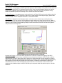
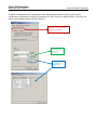
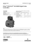
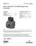
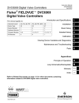
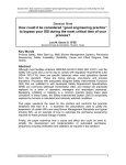
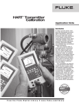
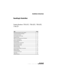
DeltaV SIS Whitepaper September 2009 – Page 1 DeltaV SIS HART Capabilities DeltaV SIS HART Capabilities This document describes various HART capabilities that can be used with the DeltaV SIS. In addition, best practices for the implementation of SIS HART diagnostics in the SIS and BPCS are detailed. www.DeltaVSIS.com DeltaV SIS Whitepaper September 2009 – Page 2 DeltaV SIS HART Capabilities Table of Contents Introduction.............................................................................................................................. 3 Specific DeltaV SIS HART Parameters................................................................................... 3 Built-in HART Device Status Signals.................................................................................... 3 Additional HART parameters................................................................................................ 5 Fisher DVC6000................................................................................................................... 6 Safety Certified Rosemount 3144P Temperature Transmitter.............................................. 8 Micro Motion Coriolis MVD Single Variable Flow Transmitter Model 1700........................... 8 Micro Motion Coriolis MVD Multivariable Flow and Density Transmitter Model 2700........... 9 PlantWeb Alerts ....................................................................................................................... 9 Other Best Practices ....................................................................Error! Bookmark not defined. Additional White Papers ..............................................................Error! Bookmark not defined. DeltaV SIS Whitepaper September 2009 – Page 3 DeltaV SIS HART Capabilities Introduction HART diagnostics in SIS field devices have been used for many years by several different SIS vendors. The HART diagnostics provide much more information on the health of a field device than can be determined from a standard 4-20 mA signal. For this reason, greater SIL (by turning Dangerous Undetected failures into Dangerous Detected failures) and longer proof testing intervals can be achieved by field devices running HART diagnostics. Most SIS vendors do not have the capability to use the HART diagnostics in the SIS logic. Instead, their systems simply use HART multiplexers to strip off the HART signal, usually on a Field Termination Assembly (FTA), and then send the HART signal to a separate AMS platform to alert the maintenance group of unhealthy devices. These SIS do not have the capability of using the HART diagnostics directly in the SIS logic. Nor do these systems have the capability of efficiently generating operator graphics, alarms, or historization of the device diagnostics. The DeltaV SIS, however, has the capability to either pass on the diagnostics to an Asset Management System (AMS) or the Basic Process Control System (BPCS) or to use the diagnostics in the SIS logic. This capability has many added benefits over traditional SIS: The SIS can use the HART diagnostics to determine if a field device is unhealthy. If the device is unhealthy the SIS can take action to remove the device from voting or trip the system if required. The HART diagnostics can be displayed on detailed operator faceplates or displays to efficiently alert the operator and the maintenance group of unhealthy devices. Historization of HART alarms can be recorded with the same tool as the BPCS and SIS alarms. The alarm banner on the operator graphics can show HART alarms, which will quickly alert the operator of critical devices that are unhealthy and require greater monitoring from the operator. Different HART signals can be used to monitor and alarm various conditions in the field without the requirement to run separate wiring for these signals - resulting in significant cost savings. This document will review several HART parameters and best practices to be used in the application of HART in the DeltaV SIS to ensure PlantWeb capabilities are fully realized. This document also uses Rosemount and Fisher device capabilities to describe the HART protocols. Other vendors may use slightly different configuration/functionality for their HART devices. Specific DeltaV SIS HART Parameters Built-in HART Device Status Signals The DeltaV SIS automatically reads various HART status signals from transmitters and the DVC6000 and can determine device health based on these parameters. These parameters can be configured to assign a faulty status to the device and perform the following: Degrade transmitter voting –If a transmitter is determined to be bad via these built-in HART status signals the SIS can either remove the transmitter from the voting logic (i.e. a 2oo3 voted group of transmitters degrades to 1oo2 or 2oo2 with the bad transmitter viewed as faulty) or the transmitter can be simply alarmed via operator graphics. Trip a valve – While unlikely to be used due to availability concerns, the built-in HART device status signals can be used to trip valves that use a HART-enabled positioner or alarm the valve via operator graphics. The following built-in HART device status signals are used: PV out of limits Analog-digital mismatch PV output saturated DeltaV SIS Whitepaper September 2009 – Page 4 PV output fixed Loss of digital communications Field device malfunction DeltaV SIS HART Capabilities It is up to the end user to determine if these status signals should be used for transmitter voting degradation or tripping of valves. Configuration of these built-in HART status signals that affect transmitter or valve status within the DeltaV logic can be performed via the DeltaV Explorer. After creating a HART enabled channel in a SLS (HART-enabled analog input or two-state output channel), drill down into the channel and double click on the HART_ERRORS parameter. By default, the SLS will ignore all of the built-in status signals. PV Out of Limits – The HART instrument is reporting that the primary variable read by the transmitter is outside of the 4-20 mA range. This signal can be used to detect open/short circuits in the transmitter wiring. Analog-Digital Mismatch – The HART instrument is reporting a difference between the analog 4-20 mA signal and the digital PV signal. This functionality can be used to determine a small ground in the home run cable to the instrument or an intermittent device. If a small ground exists in the loop, the trip limit of the device may never be reached even under trip conditions due to earth leakage. This diagnostic should detect the difference and the SIS can perform the required action (trip or alarm). PV Output Saturated – The analog and digital signals for the Primary Variable are beyond their limits and no longer represent the true applied process. If the process variable goes outside of the 4-20 mA range, the HART transmitter will drive the mA output and the PV to the saturation values, but no further. The transmitter will clamp the analog output and PV to the saturation values (not the 4 and 20 mA values). PV’s between the 4-20 mA limits and the saturation limits may still be valid signals. The following diagram is taken from a Rosemount 3051S pressure transmitter user manual. The low and high saturation (3.9 mA and 20.8 mA respectively in the Alarm Level) are the saturation setpoints. The 3.75 mA and 21.75 mA values are the transmitter failure setpoints: DeltaV SIS Whitepaper September 2009 – Page 5 DeltaV SIS HART Capabilities It should be noted that this is a digital HART alarm that is separate from the open/short circuit detection performed by monitoring the 4-20 mA analog signal in the SLS. Usually, SIS transmitters are configured in the SLS to detect faulty transmitters (open/short circuit) by monitoring the 4-20 mA analog signal and removing a transmitter from a voting configuration when that analog signal is outside of a specified range. It is good engineering practice to set the faulty transmitter ranges for the 4-20 mA analog value in the SLS equal to the failure alarm setpoints from the HART device. If the transmitter detects an error, it will send the PV to the failure alarm setpoint. Values within the low/high saturation areas are still valid values according to the transmitter. If faulty transmitter setpoints using the 4-20 mA signal in the SLS are set within the saturation range, spurious trips of the process may occur even though the transmitter may not be faulty. PV Output Fixed - The analog and digital signals for the Primary Variable are held at the requested value. They will not respond to the applied process. The output is fixed when a transmitter has been taken out of service during calibration or maintenance (changing a range, for example). Unless the transmitter has been put back in service, the outputs will continue to be fixed indefinitely. Loss of Digital Comms – This status bit is set when the HART digital communications with the device is lost. The 4-20 mA analog signal may still be valid, but the digital HART signal is not available. Field Device Malfunction - The device has detected a hardware error or failure on the device. This pertains to a variety of errors that can occur. Malfunctions in the memory, A/D converters, CPU, etc are covered under this status bit. Additional HART parameters In addition to the built-in HART status bits, several other HART variables can be used. These HART variables are dependent on the type of device. While the status signals can be used directly in the SIS logic, these additional HART parameters pass through the SIS to the BPCS and AMS. If these parameters are to be used in SIS logic, they must first be programmed in the BPCS as a parameter reference and then sent down to the SIS logic. DeltaV SIS Whitepaper September 2009 – Page 6 DeltaV SIS HART Capabilities It should be noted that HART is not a safety-rated platform. You should NEVER substitue HART signals for hardwired signals when the hardwired signal is being used to detect a hazardous condition with a SIL rating. For example, valve position is a HART parameter in the DVC6000. If valve position is being used to detect a hazardous condition with a SIL rating, the valve position must be read using limit switches or position transmitters. However, if valve position is a diagnostic used to determine the status and health of the valve, then the HART parameter can be used. HART should only be used for diagnostic purposes. Fisher DVC6000 Most Rosemount devices use the HART_PV, HART_SV, HART_TV, and HART_FV variables to send configurable device information to the DeltaV and DeltaV SIS. The Fisher DVC6000 sends four configurable slot variables in addition to the HART variables (which are not configurable in the DVC6000). The HART variables in the DVC6000 are: HART_PV – Loop Current, mA or % HART_SV - Auxiliary Contact Status, 0 or 100% HART_TV - Output Pressure, psi, bar, or kPa HART_FV - Travel, % The slot codes are programmable in the I/O channel in the logic solver. For example, to see the air supply pressure (slot code 8) in the DeltaV, drill down to the DVC channel in the SIS logic solver in DeltaV Explorer. Then, change the slot code number to 8. Use an external parameter reference in a DeltaV control module to reference the slot code. The possible slot variables and codes are: 0 – Loop Current 1 – Auxiliary Contact Status (0% = Open, 100% = shorted) 2 – Pressure P1 3 – Position 4 – Drive Signal 5 – Pressure P2 6 – Valve Setpoint 7 – Differential Pressure (P1 – P2) 8 – Supply Pressure 211 - DVC Internal Temperature Partial Stroke Testing (PST) – Initiating a partial stroke test and the success of the partial stroke test are HART parameters that are used in the DVC6000. The partial stroke test can be initiated in the DeltaV SIS, AMS, an operator graphic, or via a HART handheld device. The test is run in the DVC6000 and the success/failure of the test is sent back to the SIS and/or AMS to be shown on operator graphics or for historization. It is good engineering practice to include the requirement for a successful partial stroke test during any commissioning process for a valve with a DVC6000 as the positioner. Both the max travel movement and the travel speed of the PST are configurable. Automatic Test Interval – The DeltaV SIS and the DVC6000 can be used to automatically start partial stroke tests at required intervals. An alarm can be created to alert the operator that a partial stroke test is about to occur. In addition, the last successful partial stroke test time can be displayed on operator graphics, as well as the time until the next partial stroke test is due. DeltaV SIS Whitepaper September 2009 – Page 7 DeltaV SIS HART Capabilities Valve Position – Valve position is a HART signal that is present in the DVC6000. Valve position can be read in the BPCS and SIS via the HART_FV parameter from the device. Valve command disagree alarming can then be performed in the BPCS or SIS based on the HART command, rather than having the requirement of using hardwired methods to perform this alarming via limit switches or position transmitters. Air Supply Pressure – Air supply pressure can be configured in the DeltaV SIS as a slot code variable (code # 8) that can be read in the DeltaV. The pressure value can be used to detect low and high air supply pressure and possible plugging of the air supply line via water, oil, or particulate matter. Valve Friction – Valve friction and subsequent wear on the valve can be detected by monitoring the valve signature when a PST has occurred. A valve signature can be taken when a valve is put into service. When a PST is performed at a later time, the valve signature can again be taken and compared with the initial PST valve signature. Valve friction can be detected by looking for erratic movements of the valve on the valve signature compared with the initial signature. Safety Certified Rosemount 3051S Pressure Transmitter Impulse Line Plugging – One of the HART diagnostics for the 3051S is impulse line plugging. The 3051S determines a plugged impulse line by monitoring the normal deviations in pressure. Under normal conditions, slight deviations or noise in the pressure will be present on a millisecond scale. As flow decreases or plugging occurs in the impulse line, these deviations will decrease to a minimum value. Care should be taken when using this diagnostic to ensure that that plugged impulse line alarms are masked or transmitter failure actions are cancelled when there is no flow in the process (such as when the unit is shutdown or when miminum flow conditions exist). Additional logic in the BPCS or SIS may be required to mask this alarm during no or low flow conditions. DeltaV SIS Whitepaper September 2009 – Page 8 DeltaV SIS HART Capabilities Damping – Damping is a configurable value in HART transmitters that introduces a delay in the output of a transmitter. This parameter is used to smooth variations in output readings when sharp, rapid changes to the process input occurs. The factory default value is 3.2 seconds. Care should be taken when using this variable in SIS loops. SIS applications sometimes have a delay timer in logic (usually around 500 msec to 1 sec) to avoid spurious trips when short spikes occur with the process variable. The SIS should be engineered to ensure that the damping in the transmitter coupled with the delay timer in the SIS logic does not exceed Process Safety Time (PST) requirements for the Safety Instrumented Function (SIF). Terminal Temperature – Terminal temperature is a measure of the temperature on the transmitter. It is not a measure of the process temperature. The sensor temperature can be read in the BPCS or SIS via a HART parameter (default is the HART_SV parameter) and can be used as a check to determine that heat tracing is functioning properly. This parameter could also be used as an aid to determine if impulse lines have plugged in processes where plugging occurs when heat tracing has failed. Safety Certified Rosemount 3144P Temperature Transmitter Thermocouple Redundancy – The 3144P has redundant sensors. This redundancy can reduce the number of spurious trips that occur due to the fact that the secondary sensor can supply the temperature measurement if the primary fails. There are several different variations of the 3144P that can be ordered. SIS applications will generally use the U2 (Average Temperature with Hot Backup and Sensor Drift Alert – Warning Mode) or U3 (Average Temperature with Hot Backup and Sensor Drift Alert – Alert Mode). Sensor Drift Alert – One of the best methods of detecting sensor drift and subsequent failure is via deviation alarming. This capability is a built-in, configurable feature in the 3144P. If deviation alarming is used in the transmitter as a HART alarm or in the SIS as a programmed alarm in logic, this credit should be used in the SIL calculations. Damping – See the damping description for the 3051S. The default damping in the 3144P is 5 seconds. Terminal Temperature – See terminal temperature description for the 3051S. Sensor Types – Different sensor types, such as a RTD and a thermocouple, can be used when the dual sensor configuration is chosen. This can reduce the amount of common cause in the sensor and should be reflected in the SIL calculations. Micro Motion Coriolis MVD Single Variable Flow Transmitter Model 1700 Mass or Volume Total – Mass or volume total can be used, particularly in tank farms, pipelines, and terminal management applications, when the total amount of material that has passed through the transmitter in a period of time is requested. DeltaV SIS Whitepaper September 2009 – Page 9 DeltaV SIS HART Capabilities Micro Motion Coriolis MVD Multivariable Flow and Density Transmitter Model 2700 Temperature – Temperature can be used for deviation alarming with other temperature transmitters nearby in the process to detect faulty temperature transmitters if the deviation becomes too large. Density – Density can be used for detection of dual phase liquids or for the detection of foreign material that may not be desired in the process flow. Density can be used to check the quality of the process material or to detect plugging in the flow tube. Tube Frequency – Coriolis meters detect flow by measuring the vibration frequency of the piping in which the process flows. By monitoring for low tube frequency a plugged flow line can possibly be detected. In addition, an unusually high tube frequency can indicate sensor erosion. Drive Gain – Excessive drive gain can be the result of excessive slug flow (liquid in a gas flow or gas in a liquid flow). Slug flow can be caused by cavitation or flashing of liquids. By monitoring the drive gain, slug flow can be detected. In addition, erratic drive gain can be the result of foreign material caught in the flow tubes. External Pressure/Temperature – External pressure and temperature may indicate the need for pressure/temperature compensation that should be performed. Damping – See the damping description for the 3051S. PlantWeb Alerts PlantWeb alerts can be applied to all HART devices in the DeltaV SIS. These alerts can be monitored either from AMS or in operator graphics. User manuals and other white papers exist that describe these alerts in detail. Therefore, only a brief description of these alerts will be given here. These alerts can be pulled up by an operator or a maintenance group from the operator graphics. Access to these alerts is from the faceplate for an instrument on an operator graphic. The DeltaV SIS is the only SIS on the market that allows these PlantWeb alerts to be seamlessly and efficiently displayed to operators and maintenance technicians. Other vendors either require the use of HART multiplexers, an AMS, and a connection between the AMS and the BPCS in order to see the HART alerts on an operator graphic. The DeltaV system also can historize these alarms in the same SOE recorder or historian as other SIS alarms. This creates one repository for SIS alarms, rather than several different databases between the AMS and the BPCS. DeltaV SIS Whitepaper September 2009 – Page 10 Pulls up detailed display for HART alerts (can be used without AMS). DeltaV SIS HART Capabilities Pulls up AMS for HART alerts. DeltaV SIS Whitepaper September 2009 – Page 11 DeltaV SIS HART Capabilities In addition, PlantWeb alerts are configurable to allow different alarm priorities to exist for different alerts. Configuration is performed by selecting the properties for a HART device from DeltaV Explorer. From there, the alarms can be enabled and the priorities configured. Enables the HART alerts to be displayed in the Alarm Banner and the Alarm Summary. Selects the HART faceplate to be used for the instrument. Configures the priorities for the HART alerts. DeltaV SIS Whitepaper September 2009 – Page 12 DeltaV SIS HART Capabilities Other Best Practices In addition to other best practices outlined in this document, the following items should be addressed when using HART devices. Currently, HART 5 devices can only use eight characters in the tag name for the device. The DeltaV/DeltaV SIS can read HART 5 devices, and currently Rosemount transmitters are generally HART 5 devices. This requirement should be taken into account when assigning tag name standards in the SIS and the BPCS. Many Rosemount and Fisher user manuals supply diagnostic tests to be used during proof test intervals, including the diagnostic coverage factor. The diagnostic coverage factor should be used in SIL calculations to provide an accurate representation of the percentage of dangerous undetected faults discovered from the diagnostic routine. Loss of HART communications will not trip a DVC6000. If HART communications to the DVC6000 is lost but the 4-20 mA signal is still active, the DVC6000 will still continue to operate the valve. In addition, if HART errors are not ignored (for example, you have chosen to trip the valve if PV output is fixed) the valve will continue to operate if HART communications are lost. This function can be tested by connecting a DVC6000 to the SIS logic solver and placing a 10 µF capacitor across the + and – terminals. The capacitor will cause HART communications to be lost but will allow the 4-20 mA signal to reach the DVC6000. The DVC will still continue to operate and keep the valve in the operating position even though HART communications are lost. PlantWeb alerts for HART devices are only activated when they are enabled via the checkbox in the channel properties dialog box. During FAT, it may be beneficial to disable the PlantWeb alerts so that fewer alarms will be shown during testing when the actual device is not connected to the DeltaV SIS. PlantWeb alerts for HART devices do not require the physical presence of the device in order to be programmed. Additional White Papers These White Papers also discuss the use of HART in Emerson systems and may be of value: 1. “Using HART to Increase Field Device Reliability”. Adler, Bud. ISA. 2001. 2. “Configuring PlantWeb Alerts in a DeltaV System”. Emerson White Paper. March 2009. 3. “DeltaV HART Capabilities”. Emerson White Paper. March 2009 To locate a sales office near you, visit our website at: www.DeltaVSIS.com Or call us at: Asia Pacific: 65.777.8211 Europe, Middle East: 41.41.768.6111 North America, Latin America: +1 800.833.8314 or +1 512.832.3774 For large power, water, and wastewater applications contact Power and Water Solutions at: www.EmersonProcess-powerwater.com Or call us at: Asia Pacific: 65.777.8211 Europe, Middle East, Africa: 48.22.630.2443 North America, Latin America: +1 412.963.4000 © Emerson Process Management 2009. All rights reserved. For Emerson Process Management trademarks and service marks, go to: http://www.emersonprocess.com/home/news/resources/marks.pdf. The contents of this publication are presented for informational purposes only, and while every effort has been made to ensure their accuracy, they are not to be construed as warrantees or guarantees, express or implied, regarding the products or services described herein or their use or applicability. All sales are governed by our terms and conditions, which are available on request. We reserve the right to modify or improve the design or specification of such products at any time without notice. www.DeltaVSIS.com