1
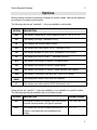
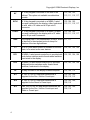
ELECTRONIC DISPLAYS INC.
135 S. CHURCH STREET
ADDISON, ILL. 60101
www.electronicdisplays.com
NUMERIC PRODUCTS MANUAL
Thank you for purchasing and Electronic Displays Inc. numeric
model. If for any reason you need technical support please visit our
support site http://edisupport.helpserve.com/.
Electronic Displays, Inc.
Thank you for purchasing this high-quality EDI product. We value your business.
This document covers what you need to know to install and use the display. If, after a
careful reading, If you feel you need assistance after consulting this manual, please
contact our technical staff at http://edisupport.helpserve.com
If you would like a full catalog of our counters, timers, message marquees, industrial
scoreboards, or any of our other products, please contact EDI customer service.
Made Proudly in the USA
Unpacking
Open the box carefully to avoid cutting or scratching the unit.
Mounting
These displays are available in a variety of enclosures, or without any enclosure.
NEMA 1 and NEMA 12 enclosures
There are two ¼–20 Rivnuts on the top of the unit, with 1¾" bolts already installed. To
avoid damaging the Rivnuts, don’t tighten the bolts beyond 20 foot-pounds.
We do not recommend drilling other mounting holes. You are likely to damage the
circuit board.
NEMA 4 and NEMA 4X enclosures
The display is designed to hang from a ceiling or mount to a wall using the two 5/16"
holes at the top of the brackets.
panel mount
These models are bolted to an oversized plastic filter. You can drill holes in the filter to
fit your mounting needs. The standard filter is acrylic (Plexiglas). A Lexan™ filter is
optional.
2
Copyright © 2004 Electronic Displays, Inc.
Power Supply
The display operates on 60Hz, 120V AC. (Models operating at 12V and 24V AC, 12V
DC, and 50Hz, 220V are available.) It is equipped with an 18-gauge, three-wire cord,
which should be connected to a properly grounded receptacle. Do not try to defeat the
grounding.
Warning — Shock Hazard
Line voltage (120V AC) is present inside the unit. Completely disconnect power before
opening. Do not operate the unit unless the covers are in place and screwed down.
Service
This display has no user-serviceable parts. The cover can be cleaned using a mild
glass-cleaning solution and a soft cloth.
Warranty
Our standard warranty is one year, parts and labor, when the product is returned
shipping charges-prepaid to Electronic Displays for repair.
Please contact our service department before returning the unit, so we can confirm
whether service is required.
Electronic Displays repair department
Unit A
135 South Church Street
Addison, IL 60101
(630) 458-9611 [voice]
(630) 628-0936 [FAX]
http://edisupport.helpserve.com
2
Seven-Segment Displays
3
Options
Options can be ordered to customize a display for specific needs. Options are indicated
by suffixes to the basic model number.
The following options are “standard” — they are available on all models.
OPTION
12AC
DESCRIPTION
The display is powered by a user-supplied source of 10V to 12V AC.
6D
The display is six-digit. (Standard is four.)
DF
Two displays are mounted back-to-back.
GR
The display uses indoor green LEDS. (Standard is red.)
HZ
The display operates on 220V 50Hz. (Standard is 120V 60Hz.)
LX
The display face filter is Lexan™. (Standard is acrylic.)
N12
The display is mounted in a NEMA 12 rated extrusion.
N4
The display is mounted in a NEMA 4 rated cabinet.
N4X
The display is mounted in a NEMA 4 rated stainless-steel cabinet.
PM
The display is mounted to the face filter. There is no cabinet.
PMNF
YL
The display has neither a face filter nor a cabinet.
The display uses indoor yellow LEDS. (Standard is red.)
Some options are “specific” — they are available, or not available, on specific models.
The following options are available only on the listed models.
OPTION
DESCRIPTION
available models
AO
The display includes an audible output that sounds
for three seconds when a set point is reached.
103, 104, 105, 110
DP1
The display can include a floating decimal point. Its
position is set when the user recalibrates the
display.
111, 117
3
4
Copyright © 2004 Electronic Displays, Inc.
A 16-key keypad is mounted on the rear of the
cabinet. This option not available on cabinetless
models.
103, 104, 105,
110, 111, 115, 117
KYN1
A 16-key keypad is mounted on a NEMA 1 rated
box and connected to the display, either hard-wired
or with with a 10' cable and a 25-pin sub-D
connector.
103, 104, 105,
110, 111, 115, 117
KYN12
A 16-key keypad is mounted on a NEMA 12 rated
box and connected to the display with a 10' cable
and a 25-pin sub-D connector.
103, 104, 105,
110, 111, 115, 117
KY
NAD
A SPST push-button switch is mounted on the end
plate, to be wired as the user desires.
102, 103, 104, 109
RC1
A NEMA 1 rated remote-control box is provided with
push-button switches and/or thumb-wheel switches,
hard-wired to the display.
102, 103, 104, 109
RC2
A NEMA 12 rated remote-control box is provided
with push-button switches and/or thumb-wheel
switches, hard-wired to the display.
102, 103, 104, 109
RL
A relay mounted in the display closes at setpoint.
103, 104, 110
XF1
A 120V to 12V AC step-down transformer is
supplied for the Run / Hold or Count input.
102, 103, 104,
109, 110, 115
XF2
A 120V to 12V AC step-down transformer is
supplied for the Reset or Preset input.
102, 103, 104,
109, 110
XF3
Two 120V to 12V AC step-down transformers are
supplied for the Run / Hold or Count input and
Reset or Preset input.
102, 103, 104,
109, 110
P1
4
The display has a “non-addressable” protocol, which 111, 117
is identical to the standard protocol except for
deletion of the two-digit address.
Seven-Segment Displays
5
The following options are available on all models except those listed.
OPTION
DESCRIPTION
excluded models
12DC
The display is powered by a customer-supplied
source of 10V to 12V DC. This option is not
available on models that use the AC line frequency
as a timebase, or do not have an internal timebase.
101
24DC
The display is powered by a customer-supplied
source of 24V to 28V DC. This option is not
available on models that use the AC line frequency
as a timebase, or do not have an internal timebase.
101
5D
The display has five digits. This option is not
available for clock displays.
101, 102, 103,
104, 106, 113
7D
The display has seven digits. Not available for clock
displays.
101, 102, 103,
104, 106, 113
8D
The display has eight digits. Not available for clock
displays.
101, 102, 103,
104, 106, 113
BT
Display values and user-alterable parameters are
retained in battery-backed memory and restored
after power loss.
105, 112, 114
DP2
A fixed decimal point is displayed at a position
specified when the display is ordered. Not available
for clock displays.
102, 103, 104,
106, 113
SD1
A 25-pin female sub-D connector is mounted on the
end of the display for the detachable keypad.
102, 109, 111,
112, 114, 117
SD2
A 9-pin femae sub-D connector is mounted on the
end of the display for the detachable keypad.
102, 109, 111,
112, 114, 117
SR1
The serial data interface is RS-232.
105, 112, 114
SR2
The serial data interface is RS-422/485.
105, 112, 114
5
6
Copyright © 2004 Electronic Displays, Inc.
Clocks
General Information
Clocks use the line frequency for their timebase. The 50/60 Hz setting is internal and
hard-wired. It cannot be changed. An optional internal timebase is available for DC
operation.
model 101
stand-alone clock / primary time display
The 101 is a primary clock. It can control the 113 secondary display using the TX+ and
TX– connections on the internal terminal strip.
The four-digit models display time in HH:MM format. The six-digit model displays time in
HH:MM:SS format.
The default display is 12 hours. (There is no AM/PM indication.) To switch the display to
24-hour, remove the plug from the back panel. Using chain-nose or needle-nose pliars,
remove the wire jumper on the 8-pin DIP socket.
When the display is plugged in, the clock reads the time from an internal batteryoperated clock chip and sets the display. Whenever the display is updated or reset,
the internal clock chip is set to the same time.
The clock battery is a primary lithium cell soldered to the PC board. It should last
several years under normal use. The display should be returned to Electronic Displays
for battery replacement.
Two momentary push-button switches on the right side set Hours and Minutes. Holding
down either switch advances the setting rapidly. Seconds are set to “zero” at the
moment you release the Minutes switch.
User-supplied switches can be wired to the internal terminal strip for remote setting.
6
Seven-Segment Displays
7
model 113
secondary display for Perfect Time system and
Masterless Master-Time system
The 113 models are four- or six-digit secondary displays controlled by the 101 primary
display over an RS-422/485 interface.
A multi-drop daisy-chain RS-422/485 interface permits up to 30 displays to be controlled
by a single primary clock. The maximum length of the cabling (which must be suitable
for an RS-422/485 connection) is 1000'.
If there is no data input when the unit is plugged in, it reads the time from an internal
battery-operated clock chip and sets the display. The clock chip is updated when the
primary display sends the correct time.
The clock battery is a primary lithium cell soldered to the PC board. It should last
several years under normal use. The display should be returned to Electronic Displays
for battery replacement.
The display is updated once per second. If five seconds pass without data input, the unit
adds five seconds to the internal clock chip’s time and starts counting on its own, using
the clock chip’s timebase. There is no visual indication that the data signal has been
lost.
Timers
General Information
Timers use the line frequency for their timebase. The 50/60 Hz setting is hard-wired. It
cannot be changed. An optional internal clock is available, permitting DC operation.
When timers are first turned on, they execute a self-test that displays all ten digits in all
four positions. They then display – – – X, where X is a digit indicating the baud rate for
devices having a serial interface doesn’t show it. For timers with a serial interface, the
default rate is 1200 baud.
7
8
Copyright © 2004 Electronic Displays, Inc.
model 102
up-timer with run / hold / reset
The four-digit displays count minutes and seconds (MM:SS) or hours and minutes
(HH:MM). The six-digit display counts hours, minutes, and seconds (HH:MM:SS).
The four-digit displays count up to 99:59, then roll over to zero and continue to count.
The six-digit display counts up to 99:59:59, then rolls over to zero and continues to
count.
User-supplied momentary-contact switches must be connected to the internal terminal
strip for Run / Hold and Reset.
Counting begins (or continues) when the input 1 switch is closed. (It can remain closed,
but doesn’t have to.) The timer pauses (holds) when the switch is briefly closed a
second time. Closing the input 2 switch resets the counter to zero.
The switches can be powered by the Vext supplied by the unit (dry contact), or external
DC of 5 to 24 volts (wet contact), as shown below.
model 103
down-timer with preset, run / hold
The four-digit displays count minutes and seconds (MM:SS) or hours and minutes
(HH:MM). The six-digit display counts hours, minutes, and seconds (HH:MM:SS).
When counting down, all the timers stop at zero minutes and zero seconds. During a
down-count, if the preset number of seconds is greater than 61, the timer immediately
jumps to 59 seconds when it starts to run.
The preset time is selected using the four thumbwheel switches on the right side. On
the six-digit model, the seconds preset is fixed at 00.
When plugged in, the display is automatically set to the switch values. The Preset
switch resets the display to the current switch values, even if the timer is running, and
8
Seven-Segment Displays
9
the timer continues to run.
As shipped, the Preset switch is installed and wired to the internal terminal strip using
the dry connections. Run / Hold requires a user-supplied locking or toggle switch. The
timer runs when this switch is closed, and holds (pauses) when the switch is open.
The switches can be powered by the Vext supplied by the unit (dry contact), or external
DC of 5 to 24 volts (wet contact), as shown below.
model 104
up / down timer with preset, direction, run / hold
The four-digit displays count minutes and seconds (MM:SS) or hours and minutes
(HH:MM). The six-digit displays counts hours, minutes, and seconds (HH:MM:SS).
The four-digit displays count up to 99:59, then roll over to 00:00 and continue to count.
The six-digit display counts up to 99:59:59, then rolls over to 00:00:00 and continues to
count.
When counting down, all the timers stop at zero minutes and zero seconds. During a
down-count, if the preset number of seconds is greater than 61, the timer immediately
jumps to 59 seconds when it starts running.
The preset time is selected using the four thumbwheel switches on the right side. On
the six-digit model, the seconds preset is fixed at 00.
When plugged in, the display is automatically set to the switch values. The Preset
switch resets the display to the current switch values, even if the timer is running, and
the timer continues to run.
The Direction switch reverses the timer’s current direction, and the timer continues to
run. When plugged in, the timer’s default direction is up.
As shipped, the Direction and Preset switches are installed and wired to the internal
terminal strip using the dry connections. Run / Hold requires a user-supplied locking or
toggle switch. The timer runs when this switch is closed, and holds (pauses) when the
9
10
Copyright © 2004 Electronic Displays, Inc.
switch is open.
The switches can be powered by the Vext supplied by the unit (dry contact), or external
DC of 5 to 24 volts (wet contact), as shown below.
10
Seven-Segment Displays
11
Counters
General Information
When counters are first turned on, they execute a self-test that displays all ten digits in
all four positions. They then display – – – X, where X is a digit indicating the baud rate.
For counters with a serial interface, the default rate is 1200 baud.
model 109
up counter with reset
When plugged in, the counter displays 0000. When the count reaches 9999, it rolls over
to 0000 and continues.
Counting requires a user-supplied momentary-action switch connected to input 1 on the
internal terminal strip. The counter increments when this switch is closed, then opened.
Holding it closed does not produce a continuous increment.
A user-supplied momentary-action switch connected to input 2 on the internal terminal
strip resets the counter. The counter resets when the switch is closed.
The switches can be powered by the Vext supplied by the unit (dry contact), or external
DC of 5 to 24 volts (wet contact), as shown below.
11
12
Copyright © 2004 Electronic Displays, Inc.
model 110
up/down counter with preset, direction, count
The preset is selected using the four thumbwheel switches on the right side. When
plugged in, the display is automatically set to the switch settings. The Preset switch
resets the display to the current switch settings.
The Direction switch reverses the counter’s current direction. When plugged in, the
timer’s default direction is up (increment).
When counting down, the counter stops at 0000. When counting up, the counter stops
at 9999 without rolling over.
As shipped, the Direction and Preset switches are installed and wired to the internal
terminal strip using the dry connections. Direction is input 2 and Preset is input 3 (not
shown).
Count (input 1) requires a user-supplied momentary-action switch. The counter
increments / decrements each time this switch is closed, then opened.
The switches can be powered by the Vext supplied by the unit (dry contact), or external
DC of 5 to 24 volts (wet contact), as shown below.
12
Seven-Segment Displays
13
Data Displays
models 111 & 117
data displays
The 111 and 117 are multi-digit data displays. They are identical, except for the
interface. The 111 has an RS-232 interface, the 117 an RS-422/485, as shown below.
The data input connects to the Sig+ and Sig– inputs.
RS-232 transmission should be at 1200 baud, 8 data bits, 1 stop bit, no parity. We do
not recommend paralleling multiple 111 units, as the RS-232 standard is not designed
for such operation.
A multi-drop daisy-chain RS-422/485 interface permits up to 30 117 displays to be
controlled by a single device (terminal or computer). The maximum length of the cabling
(which must be suitable for an RS-422/485 connection) is 1000'.
When the unit is plugged in, the display cycles through all the digits in each position
(0000, 1111, 2222, and so on), to confirm the LEDs are working.
It then cycles through a sequence that shows the address (Axx), the baud rate (bx), the
display length (Uxx), and the display protocol (–n). The sequence is repeated
indefinitely until a data stream appears at the input (RS-232 or RS-422/485).
The data stream comprises a start character, an address, the data, and a stop
character. There are no spaces in the data stream, unless they are part of the data.
•
The start character is CTRL+B. (Press and hold the CTRL key, then press B.)
•
The address is the address of the unit that is to display. It is two ASCII digits. The
leading zero is required for addresses between 00 and 09. When the address is 00,
every unit displays the data.
•
The data are as many ASCII digits as required to fill the display, plus a decimal point
(if needed). If there’s a minus sign (–) for negative values, the number of digits that
can be displayed is reduced by one. A space can replace any of the digits.
•
The stop character is CTRL+C. (Press and hold the CTRL key, then press C.)
To display the values –3.14 and 2.78, separated by two spaces, on a ten-digit display
with an address of 15, you would transmit the following sequence of fifteen ASCII
13
14
Copyright © 2004 Electronic Displays, Inc.
characters, either from a terminal or a computer program.
CTRL+B
15 – 3 . 1 4
SPACE SPACE
2 . 7 8
CTRL+C
The data is displayed on all units having the given address (15 in this example). 00 is
the broadcast address — the data is displayed on all units, regardless of their settings.
The default baud rate is 1200. The default address is 01. When more than one display
is purchased at the same time, their addresses are set in sequence, starting from 01.
To change the baud rate or address, remove the plastic plug on the back of the display
and set the DIP switch as shown in the following tables. Changes do not take effect until
the unit is turned off, then on again.
BAUD RATE
POWER-UP DISPLAY
switch 7
switch 8
1200
b3
OFF
OFF
2400
b4
ON
OFF
4800
b5
OFF
ON
9600
b6
ON
ON
DIP switches 1 through 6 can be set for a total of 64 addresses, 1 through 64. If you
think of switch 1 as the least-significant bit (LSB), and switch 6 as the most-signficant bit
(MSB), simply set the binary value of the address, as shown in the table examples.
IMPORTANT Setting the switches to 000000 (all OFF) sets the address to 64, not 00.
ADDRESS
switch 6
switch 5
switch 4
switch 3
switch 2
switch 1
01
OFF
OFF
OFF
OFF
OFF
ON
02
OFF
OFF
OFF
OFF
ON
OFF
03
OFF
OFF
OFF
OFF
ON
ON
04
OFF
OFF
OFF
ON
OFF
OFF
05
OFF
OFF
OFF
ON
OFF
ON
…
…
…
…
…
…
…
60
ON
ON
ON
ON
OFF
OFF
14
Seven-Segment Displays
15
61
ON
ON
ON
ON
OFF
ON
62
ON
ON
ON
ON
ON
OFF
63
ON
ON
ON
ON
ON
ON
64
OFF
OFF
OFF
OFF
OFF
OFF
There is a second “function” DIP switch that controls the display protocol.
switch
1
switch
2
switch
3
POWER-UP
DISPLAY
PROTOCOL
OFF
OFF
OFF
–0
non-addressable; LZB off
ON
OFF
OFF
–1
non-addressable; LZB on
OFF
ON
OFF
–2
2-digit addressable flexible;
LZB off
ON
ON
OFF
–3
2-digit addressable flexible;
LZB on
OFF
OFF
ON
–4
2-digit addressable decimal
locator; LZB off
ON
OFF
ON
–5
2-digit addressable decimal
locator; LZB on
•
Non-addressable means the data is displayed, whether or not the address in the
data stream matches the switch setting. Addressable means the the data is
displayed only if the address in the data stream matches the switch setting, or is 00.
•
When LZB is on, leading zeros are blanked (displayed as spaces).
•
Flexible means the displayed value can include a decimal point, a minus sign, and
spaces.
•
Decimal locator means that the decimal point is not included in the data. Its position
is indicated by the last digit in the number, which is not displayed. For example, if the
last digit is 3, the decimal point is positioned to the right of the third digit.
15
16
Copyright © 2004 Electronic Displays, Inc.
Switches 4 and 5 are reserved for future use and should be left in the off position.
Switches 6, 7, and 8 specify the length of the display.
switch
6
switch
7
switch
8
POWER-UP
DISPLAY
DISPLAY SIZE
OFF
OFF
OFF
U02
1 or 2 digits
ON
OFF
OFF
U04
3 or 4 digits
OFF
ON
OFF
U06
5 or 6 digits
ON
ON
OFF
U08
7 or 8 digits
OFF
OFF
ON
U10
9 or 10 digits
ON
OFF
ON
U12
11 or 12 digits
OFF
ON
ON
U14
13 or 14 digits
ON
ON
ON
U16
15 or 16 digits
16
PROTOCOL FOR REMOTE KEYPAD (NUMERIC DISPLAYS)
The sequence of keys to enter values on the top four lines of the
scoreboard is as follows:
1. Press the key marked with an A(upper right hand corner ‘A’).
2. Press the two numeric keys representing the desired address of
the display
3. Press the one to four numeric keys that represent the value to be
displayed
4. Press the key labeled ‘D’ (lower right hand corner)
Examples:
To display ‘1234’ on the display addressed as ‘01’, the key sequence
is as follows:
‘A’ “01” “1234” ‘D’
To display ‘987’ on the display addressed as ‘01’, the key sequence
is as follows:
‘A’ “01” “987” ‘D’
BAUD RATE @ 1200BPS ; NO PARITY ; 8 DATA BITS ; 1 STOP BIT
PROTOCOL FOR REMOTE KEYPAD – NO ADDRESSING
The sequence of keys to enter values on the top four lines of the scoreboard is
as follows:
1. Press the key marked with an A(upper right hand corner - ‘A’).
2. Press the one to four numeric keys that represent the value to be displayed
3. Press the key labeled ‘D’ (lower right hand corner)
Examples:
To display ‘1234’ on the display, the key sequence is as follows:
‘A’ “1234” ‘D’
To display ‘987’ on the display, the key sequence is as follows:
‘A’ “987” ‘D’
Questions?? Visit www.electronicdisplays.com
E-mail: [email protected]
Seven-Segment Displays
17
model 105
analog-to-digital converter with display
The 105 models convert an analog input (either voltage or current) into a four-digit
display, linearly proportional to the input.
The 105 is factory-configured to read current or voltage, over a specified range listed in
the table below. When the input is less than or equal to the lower input value, the
display reads 0000. When the input is equal to or greater than the upper input value, the
display reads 2000.
CURRENT INPUT
CODE
VOLTAGE INPUT
CODE
0 – 1 mA DC
C1
0 – 1 V DC
V1
0 – 10 mA DC
C2
0 – 2 V DC
V2
0 – 100 mA DC
C3
0 – 5 V DC
V3
1 – 5 mA DC
C4
0 – 10 V DC
V4
4 – 20 mA DC
C5
0 – 100 V DC
V5
10 – 50 mA DC
C6
0 – 200 V DC
V6
-1 – +1 mA DC
C7
0 – 500 mV DC
V7
-10 – +10 mA DC
C8
1 – 5 V DC
V8
The last three sections of the model number indicate the input type and range, and the
factory calibration. For example, an ED400-105-4D-N1-C5-0-2000 has a currentsensing input (C5). At 4mA, the display reads 0000. At 20mA, the display reads 2000.
Calibration
The display can easily be recalibrated. You need an adjustable current or voltage
source, plus a computer, terminal, or keypad with an RS-232 serial output. (Most
computer operating systems include a terminal program, such as HyperTerminal.)
The input connects to Sig+ and Sig– on the terminal block..
Data input is through the third terminal on the block, or pin 3 on the optional DB-25.
Ground is through the fourth terminal or pin 7 on the DB-25. On a PC-type computer,
the data connection is to pin 3 (DB-15 COM port) or pin 2 (DB-25 COM port). The
17
18
Copyright © 2004 Electronic Displays, Inc.
grounds are pins 5 and 7, respectively. Please refer to the manual for your keyboard or
manual for its serial pinouts. No other connections are required.
Transmission should be at 1200 baud, 8 data bits, 1 stop bit, no parity.
No special settings or preparation are required. Simply hook the computer or terminal to
the display with the appropriate RS-232 cable.
The basic calibration procedure is to apply the miminum or maximum input to the
display, then tell it (through the serial input) what value you want displayed.
To calibrate for the minimum display…
1. Apply the minimum input to the display. (If this is zero volts or milliamps, you can
simply short the input.)
2. On the keyboard or terminal, press CTRL+B.
3. Press 0 (zero).
4. Press the four digits you want displayed for the minimum input, such as 0010.
If you want a negative display, prefix the digits with a dash (-). If you have the
floating-point option, add a decimal point (.) at the desired position.
5. Press CTRL+C.
To calibrate for the maximum display…
1. Apply the maximum input to the display.
2. On the keyboard or terminal, press CTRL+B.
3. Press 7 (seven).
4. Press the four digits you want displayed for the maximum input, such as 2999.
If you want a negative display, prefix the digits with a dash (-). If you have the
floating-point option, add a decimal point (.) at the desired position.
5. Press CTRL+C.
You can change either setting without having to change the other. If you make a
mistake, simply start over again with CTRL+B.
18
Seven-Segment Displays
19
Baud Rate
switch 7
switch 8
1200
OFF
OFF
2400
ON
OFF
4800
OFF
ON
9600
ON
ON
ADDRESS
switch 1
switch 2
switch 3
switch 4
switch 5
switch 6
64
OFF
OFF
OFF
OFF
OFF
OFF
01
ON
OFF
OFF
OFF
OFF
OFF
02
OFF
ON
OFF
OFF
OFF
OFF
03
ON
ON
OFF
OFF
OFF
OFF
14
OFF
ON
ON
ON
OFF
OFF
15
ON
ON
ON
ON
OFF
OFF
16
OFF
OFF
OFF
OFF
ON
OFF
17
ON
OFF
OFF
OFF
ON
OFF
62
OFF
ON
ON
ON
ON
ON
62
ON
ON
ON
ON
ON
ON
19