1
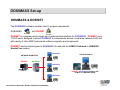
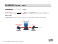
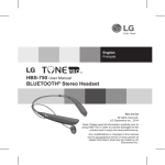
MGP Instruments Learning Center Training Module
DOSIMASS Configuration
Software Fundamentals
Introduction to Dosimeter, Reader & Software Fundamentals
About this document
The contents of this document are the sole ownership of MGP Instruments and
shall not be reproduced, distributed, altered or modified without the consent of
MGP Instruments, Inc.
Modification to the information presented in this document may result in
inaccurate operation of associated hardware and software.
Introduction to Dosimeter, Reader & Software Fundamentals
Introduction
• This session is designed to provide the attendee a basic overview of
the DOSIMASS configuration software.
• This session is prepared for individuals who are responsible for
maintenance and oversight of electronic dosimeter use.
• This session does not provide guidance in repair, calibration or
advanced use of configuration software. However, it provides the tools
for the attendee to be knowledgeable in the basic dosimeter
operation, maintenance, and troubleshooting techniques.
Introduction to Dosimeter, Reader & Software Fundamentals
DOSIMASS Overview
DOSIMASS: Dosimeter Maintenance And Set-up Software
DOSIMASS is a program designed specifically for configuration for the MGP Instruments DMC-2000
Electronic Dosimeter. DOSIMASS can also be used for the DMC-90 & DMC-100 model dosimeters,
however, with limited functionality. The DOSIMASS program can be used with the following LDM
Family of Dosimeter Readers:
• LDM-91 & LDM-101 Infrared readers
• LDM-2000, LDM-210, 220 & 230 Hands-Free readers
DOSIMASS provides individual and multiple dosimeter configuration capability, including functions
such as:
•
•
•
•
•
Readout, display and modification of the actual dosimeter parameters;
Read and archive of dosimeter parameters
Simplified Controlled Area entrance/exit functions
Troubleshooting Diagnostics and Dosimeter Repair, and,
Readout of Events Histories.
This section will provide a detailed review of the DOSIMASS software program.
Introduction to Dosimeter, Reader & Software Fundamentals
DOSIMASS Set-up
DOSIMASS & DOSINET
The DOSIMASS software contains two (2) program components:
DOSIMASS
and DOSINET
Dosimass
DOSINET is a program which serves as a communication interface for DOSIMASS. DOSINET uses
TCP/IP and is designed to allow DOSIMASS to communicate across a local area network (LAN) and
with variety of other MGP Instruments software programs and components.
DOSINET must be started (prior to DOSIMASS) if used with the LDM-101 Infrared or LDM-2000
Hands-Free readers.
DOSIMASS
NETWORK OPERATION
DOSINET
STAND-ALONE PC
NETWORK
DOSIMASS
DOSINET & DOSIMASS operating with
LDM-101 or LDM-2000 Reader
DOSIMASS
Introduction to Dosimeter, Reader & Software Fundamentals
DOSIMASS Set-up – cont.
DOSIMASS & DOSINET – cont.
The DOSINET program is not used when LDM-210 or LDM-220/230 Readers are used. These new
readers have been designed with the DOSINET communication protocol embedded into the firmware
of each reader.
The DOSIMASS program is used to configure the communication parameters of each reader.
STAND-ALONE PC
USB Communication
and Power
Serial
Communication
AC Power
LDM-220
USB Reader
Introduction to Dosimeter, Reader & Software Fundamentals
LDM-210
Serial Reader
DOSIMASS Installation
Installing DOSIMASS
From the CD, double-click the
DOSIMASS_L.exe icon.
A self-extracting utliity will prepare the
DOSIMASS installation files.
The Choose Setup Language window
appears.
Select English
Click OK
Introduction to Dosimeter, Reader & Software Fundamentals
DOSIMASS Installation
Installing DOSIMASS – cont.
The License Agreement is displayed.
Click Yes
The InstallShield Wizard starts the
installation process…
Click Next
Introduction to Dosimeter, Reader & Software Fundamentals
DOSIMASS Installation
Installing DOSIMASS – cont.
DOSIMASS will be installed to a default
directory, typically:
C:\Program Files\DOSIMASS_DM
If using another installation location, click
the Browse button to locate a specific
installation drive or directory.
If the default directory is suitable, click
the Next button
Introduction to Dosimeter, Reader & Software Fundamentals
DOSIMASS Installation
Installing DOSIMASS – cont.
The Customer Information window
appears, providing a point during the
installation to register DOSIMASS.
Using the Registration Key provided by
MGPI, enter the data in the fields as
depicted below
bsmith
nukenpp
MGP-qDSDE-02IT-CXB5S1
When completed, click the Next button
Introduction to Dosimeter, Reader & Software Fundamentals
DOSIMASS Installation
Installing DOSIMASS – cont.
The Select Program Folder permits selection of
a folder to add program icons. DOSIMASS is the
default program (on the windows desktop)
Click Next
In the Setup Type window,
select Typical.
Click Next
Introduction to Dosimeter, Reader & Software Fundamentals
DOSIMASS Installation
Installing DOSIMASS – cont.
The Select Type window permits
selection of the reader. Depending upon
the type of reader used, DOSIMASS will
be pre-configured for communication and
operation.
For example…
Select the LDM-220 Reader
(or select the reader to be used)
Click Next
Introduction to Dosimeter, Reader & Software Fundamentals
DOSIMASS Installation
Installing DOSIMASS – cont.
The Serial Port selection window provides
a serial (COM) port assignment for the
LDM-220.
Use the default value provided (5)
Refer to the section:
DOSMASS: Using the LDM-220 Reader
to identify the Com port being used by the
LDM-220.
Click Next
Introduction to Dosimeter, Reader & Software Fundamentals
DOSIMASS Installation
Installing DOSIMASS – cont.
DOSIMASS will continue installation with a
status window and progress bar.
Prior to completion, a Question window
appears, prompting the user to
acknowledge the presence of a Network
Card.
Click No (Network Card is installed)
Introduction to Dosimeter, Reader & Software Fundamentals
DOSIMASS Installation
Installing DOSIMASS – cont.
DOSIMASS then asks to install the driver
for the LDM-220 reader.
Click YES (if first time installation for an
LDM-220 on PC).
As installation finishes, the user can view a
“README” file.
Click Yes or No
(Yes will open a file to view DOSIMASS
specific information; No completes the
installation.
Introduction to Dosimeter, Reader & Software Fundamentals
DOSIMASS Installation
Installing DOSIMASS – cont.
DOSIMASS installation is complete and
prompts the user to restart the computer
(to register the installation with the
computer system files and registry).
Click Yes
Click Finish
Introduction to Dosimeter, Reader & Software Fundamentals
DOSIMASS Set-up – cont.
DOSIMASS: Using LDM-210 Serial Reader
During installation of the DOSIMASS
software, the user is prompted to select
the type of reader to be used.
Following installation, and after the reader
has been connected to the PC, the
Communication Port must be selected or
verified to ensure connectivity.
When using the LDM-210 Serial Reader,
verify the following:
• Link Type: DIRECT
• Port Number: usually 1 or 2
• Click OK
The LDM-210 Serial Reader is now ready
for use.
Introduction to Dosimeter, Reader & Software Fundamentals
NOTE:
NOTE: The
The reader
reader SHOULD
SHOULD NOT
NOT
be
connected
to
the
computer
be connected to the computer
during
during installation
installation
DOSIMASS Set-up – cont.
DOSIMASS: Using LDM-220 USB Reader
Similar to the LDM-210 Serial
Reader, the LDM-220 USB Reader
must be configured after connected
to the PC.
Prior to configuration of the LDM220 in the Exchange Parameter
feature of DOSIMASS, the User
must determine which
Communication Port has been
assigned by the computer.
To do this…
Right Mouse Click on the My
Computer Icon on the Windows
Desktop.
Select Properties
The System Properties window
opens…
Introduction to Dosimeter, Reader & Software Fundamentals
DOSIMASS Set-up – cont.
DOSIMASS: Using LDM-220 USB Reader – cont.
Click the Hardware Tab, then Device
Manager. The Device Manager will display
a list of hardware with associated
configurations and assignments
This is the Com Port
Number to be used in the
Port Number field in
DOSIMASS Exchange
Configuration
Click on Ports (Com & LPT) to expand the selection.
The LDM-220 USB Reader is identified as Cypress
USB-HD with an assigned port number.
If the Cypress USB-HD driver is not
identified….
Introduction to Dosimeter, Reader & Software Fundamentals
DOSIMASS Set-up – cont.
Manual Cypress USB-HD Driver Installation
Locate the HidComInst.exe file in the
DOSIMASS_DM installation directory:
C:\Program Files\DOSIMASS_DM
Double-click to initiate installation of the driver.
After a few moments, the driver will be installed.
To verify, connect the LDM-220 USB Reader to an
available USB port on the computer.
Open the Device Manager (as previously instructed)
and confirm the driver-and-COM Port assignment.
Introduction to Dosimeter, Reader & Software Fundamentals
DOSIMASS Set-up – cont.
DOSIMASS: Using LDM-220 USB Reader – cont.
In the DOSIMASS software, click
Setup, then Exchange…
• Link Type: DIRECT
• Port Number: (use Port Number assigned
in Device Manager)
• Click OK
The LDM-220 USB Reader is now ready for
use.
Introduction to Dosimeter, Reader & Software Fundamentals
Dosimass Install: Reader Configuration
Changing Readers in DOSIMASS
Depending upon the type of dosimeter
reader used, the Exchange Configuration
fields may have to be modified…
For use with…
• LDM-210 Serial
• LDM-220 USB
• LDM-230 PCMCIA
…select the DIRECT link type.
Enter the Port Number as assigned from the
Device Manager – Ports (COM & LPT)
Ensure the Reader Address is set for 1
Click OK
For the LDM-101, select DosiNet Link type
and Reader Address 0
Introduction to Dosimeter, Reader & Software Fundamentals
Dosimass Install: Reader Configuration
Changing Readers in DOSIMASS – cont.
If using the LDM-101 Infra-Red or LDM-2000
Hands-Free Readers, the DOSINET module
must be activated.
1. Shut down DOSIMASS.
2. Start DOSINET
3. Log in: User ID: mgpi
Password: mgpi
4. Click Setup, then Communication
5. Select the Reader Family for
the Reader to be used
6. Click OK
Introduction to Dosimeter, Reader & Software Fundamentals
Dosimass Install: Reader Configuration
Changing Readers in DOSIMASS – cont.
Start DOSIMASS (DOSINET should be
minimized, not closed)
1. Log-in
2. Click Setup, then Exchange
3. Change the Link type to DOSINET
4. Change the Port Number to 3000
5. Change the Reader Address to…
- 0 for the LDM-101
- 1 for the LDM-2000
6. Click OK
DOSIMASS is now ready for use.
Introduction to Dosimeter, Reader & Software Fundamentals
Dosimass Install: Multiple Software Installations
Multiple DOSIMASS & Reader Configurations
DOSIMASS can be configured for multiple readers on a single computer without having to modify
the configuration.
1. In Windows Explorer, locate the DOSIMASS installation directory
(typically C:\Program Files\DOSIMASS_DM)
1. Create a New Folder (e.g. DOSIMASS USB) in the same directory that DOSIMASS_DM is
installed (C:\Program Files).
2. Highlight the DOSIMASS_DM folder, then select COPY from the EDIT menu bar function.
3. Double-click the new folder, then select PASTE from the EDIT menu bar function (the
DOSIMASS_DM directory contents will be duplicated in the new folder.
4. Create a short-cut on the windows desktop using the DOSIMASS.EXE file located in the newly
create folder.
5. Run DOSIMASS and configure for the reader to be used.
6. Multiple DOSIMASS folder can be created and configure to support any reader without have to
change the configuration.
Introduction to Dosimeter, Reader & Software Fundamentals
DOSIMASS Set-up – cont.
DOSIMASS: REGISTRATION (If not performed during installation)
The DOSIMASS software must be registered
in order to permit operation of advanced
user functions.
(If registration was not performed during
installation, use this process)
MGP Instruments provides a registration to
the User upon request.
The information must be entered into the
fields exactly as it appears on the registration
form.
Introduction to Dosimeter, Reader & Software Fundamentals
DOSIMASS Navigation
DOSIMASS CONTROL PANEL
Window Frame – Title and
Software Description
(Hands(Hands-Free or InfraInfra-Red)
Menu Bar
Message Window and
Active Area
Introduction to Dosimeter, Reader & Software Fundamentals
Message Window indicating full
user access to critical parameters
DOSIMASS Navigation – cont.
DOSIMASS CONTROL PANEL – cont.
The Red Icon in the lower
right portion of the
DOSMASS Control Panel
displays the following
message:
The presence of the red icon and message indicates that DOSIMASS
has been successfully registered, permitting advanced user operation.
Introduction to Dosimeter, Reader & Software Fundamentals
DOSIMASS Menu
DOSIMASS MENU FEATURES
• Event Log
• Exit program
• Log-in and Log-out of
program
• Establish and maintain
accounts (Username,
Passwords, Access Level)
• Software & reader
communication
parameters
• Selection of
measurement display
units
• Additional Program
security
•
User Registration
•
Dosimass Version
information
• Dosimeter configurations
• Access Events History
• Activate & deactivate
dosimeter
• Assign dosimeter
Menu selections can be accessed by:
Point and click of mouse, and/or press ALT key and Underscored Letter
Letter (e.g.; ALT F) or the
CTRL key and Underscored Letter (e.g.; Ctrl+D)
Ctrl+D)
Introduction to Dosimeter, Reader & Software Fundamentals
DOSIMASS Menu
FILE
The FILE menu consists of a standard EXIT program function. This menu option can also be
accessed using the Control Q keystroke or by clicking on the X in the upper right corner of the
DOSIMASS Control Panel.
Introduction to Dosimeter, Reader & Software Fundamentals
DOSIMASS Administration
ADMINISTRATION
The ADMINISTRATION Menu features…
• Log-In & Log-out: User and Password security
• Account Management: Administration for customized User and Password assignments and security
levels
• Log-in Time out: An idle period defined to automatically log-out a User from a DOSIMASS session
Introduction to Dosimeter, Reader & Software Fundamentals
DOSIMASS Administration – cont.
DOSIMASS LOG-IN
To Log-in to DOSIMASS using the default Usernames and Passwords…
1. Click Administration,
Log in…
2. A window will appear
prompting the user to
enter a User ID and
Password…
User Id: ---------Password: ---------Click OK
Introduction to Dosimeter, Reader & Software Fundamentals
The Default User Id and Passwords
used:
•
•
•
•
Operator
Maintenance
Supervisor
Administrator
Password Management is discussed in
detail in the following slides.
DOSIMASS Administration – cont.
PASSWORD MANAGEMENT
Password Management is an important element for maintaining security and integrity of dosimeter
configurations. The DOSIMASS software has five (5) different access (security) levels. Access to
certain features is only permitted if a user possesses the required access level authorization. The
DOSIMASS Access Levels are:
•
•
•
•
•
•
None
Operator
Maintenance
Supervisor
MGP Instruments
Administrator (administrative functions only, no device configurations)
Access authorization can be tailored to a specific facility. For example, many users can be assigned
specific User ID’s and passwords for any of the Access Levels in DOSIMASS by the software
Administrator, or, in smaller facilities with few (or even one) User, the default Access Levels may be
adequate.
This section will review each of the DOSIMASS Access Levels and the feature offered in each level.
Introduction to Dosimeter, Reader & Software Fundamentals
DOSIMASS Administration – cont.
PASSWORD MANAGEMENT: ACCESS LEVELS
To Log-in to DOSIMASS using the default Usernames and Passwords…
1. Click Administration,
Log in…
2. A window will appear
prompting the user to enter a
User ID and Password…
User Id:
administrator
Password: administrator
administrator
*************
Click OK
Introduction to Dosimeter, Reader & Software Fundamentals
The password will be hidden
when entered
DOSIMASS Administration – cont.
PASSWORD MANAGEMENT: ACCESS LEVELS – cont.
To view access levels and
modify/create User IDs and
password accounts…
The User ID appears in the Title
Bar for any User loglog-in
1. Click Administration, Account
Management.
2. The Account Management
window is displayed…
Default Access Levels
(cannot be modified)
Introduction to Dosimeter, Reader & Software Fundamentals
Default User ID’
ID’s
(custom User ID’
ID’s and
Passwords can be added)
DOSIMASS Administration – cont.
PASSWORD MANAGEMENT: ACCESS LEVELS – cont.
FUNCTION
Function
LEVEL
NONE
ADMINISTRATOR
OPERATOR
MAINTENANCE
SUPERVISOR
FACTORY
User Name
----
administrator
operator
maintenance
supervisor
mgpi
Password
----
administrator
operator
maintenance
supervisor
XXXXX *
Measures
& Thresholds
Yes
Read Only
No
Yes
Partial Access
Yes - Full
Yes - Full
Yes - Full
Assignment
Yes
Read Only
No
Yes – Full
Yes - Full
Yes - Full
Yes - Full
No
No
Yes
Read Only
Yes
Read Only
Yes
Read Only
Yes - Full
Operating
Parameters
Yes
Read Only
No
Yes – Full
Yes - Full
Yes – Full
Yes - Full
Calibrations
No
No
Yes
Read Only
Yes
Partial Access
Yes
Partial Access
Yes - Full
User Block
No
No
Yes
Read Only
Yes
Partial Access
Yes
Partial Access
Yes - Full
System
No
No
Yes
Read Only
Yes
Partial Access
Yes
Partial Access
Yes - Full
Factory
No
No
No
No
No
Yes - Full
Histogram
Yes
No
Yes
Yes
Yes
Yes
Comment
Read Only
Access
Account
management only
Partial access to
select functions –
Calibration
Values Restricted
Multiple
configuration
permission
denied
Multiple
configuration
allowed
Multiple
configuration
allowed
Status
Introduction to Dosimeter, Reader & Software Fundamentals
DOSIMASS Administration – cont.
SECURITY: LOG- IN TIMEOUT
The Log-in Time Out feature provides an added level of security. DOSIMASS will log-off from
the current user if the idle time exceeds the time out threshold. To modify:
1. Click Administration,
Login Time_out
2. The Session time_out delay
configuration window will
appear.
3. In the Time_out field, enter all
9’s to maximize the idle time
(if desired).
4. Click OK
5. Close and Restart
DOSIMASS for changes to
take effect.
Introduction to Dosimeter, Reader & Software Fundamentals
DOSIMASS Setup– cont.
SET-UP: EXCHANGE
The EXCHANGE configuration
establishes Reader-to-PC
communication parameters…
The type of reader used determines
the type of communication process
required (Link Type)
Introduction to Dosimeter, Reader & Software Fundamentals
DOSIMASS Setup – cont.
SET-UP: GENERAL PARAMETERS (Post Installation Reminder)
GENERAL PARAMETERS allows for
selection of display units:
• mrem - millirem
• mSv - milliSievert
• cGy - centigray
NOTE:
ing
NOTE: The
The default
default General
General Parameter
Parameter setting
setting for
for DOSIMASS
DOSIMASS (follow
(following
installation)
is
in
units
of
mSv
(
milli
sievert
).
Prior
to
software
operation,
installation) is in units of mSv (milli-sievert). Prior to software operation,
change
milli-rem) as
change this
this setting
setting to
to mrem
mrem ((milli-rem)
as shown
shown above.
above.
Introduction to Dosimeter, Reader & Software Fundamentals
DOSIMASS Setup – cont.
SET-UP: GENERAL PARAMETERS – cont.
Default measurement
display units in mSv
(after installation)
Introduction to Dosimeter, Reader & Software Fundamentals
After changing
General Parameter
to mrem
Dosimeter Entry/Exit
OVERVIEW OF DOSIMETER ENTRY & EXIT OPERATION
This section reviews the process of activating (Entry, RUN mode) and deactivating (Exit, PAUSE mode)
a dosimeter using the Entry/Exit feature
The Entry function enables the user to:
• Activate the dosimeter
• Configure the dosimeter with new thresholds for dose alarm and warning, dose rate alarm and
warning
• Time alarm (duration)
The Exit function enables the user to:
• Deactivate the dosimeter
• Observe any alarms while the dosimeter was active
• Obtain the primary measurement values including dose, dose rate and duration while the
was active.
dosimeter
Note: The Entry/Exit function is authorized for all DOSIMASS access levels except that of the
ADMINISTRATOR level. See Password Management section for detailed access level authorization.
Introduction to Dosimeter, Reader & Software Fundamentals
Dosimeter Entry/Exit – cont.
ENTRY: ACTIVATING THE DOSIMETER
1. From the DOSIMASS Menu bar, click Dosimeter, Entry/Exit
2. A window will appear requesting insertion of, or, searching for a dosimeter (depending upon reader
type used)…
Display for Hands-Free Reader
(LDM-2000, 210 or 220)
Introduction to Dosimeter, Reader & Software Fundamentals
Display for LDM-101 Infra-Red
Reader
Dosimeter Entry/Exit – cont.
ENTRY: ACTIVATING THE DOSIMETER – cont.
Following the read sequence, the
Entry window appears…
The highlighted fields allow the
User to modify the Dose, Rate and
Time Thresholds and Warnings
Click the ENTRY button
Or press the ENTER key to
program the values into the
dosimeter
Introduction to Dosimeter, Reader & Software Fundamentals
Scientific notation is the default value
display. Modifying these values can be
performed using Standard numeric
notation (2, 50, 12.5), however, the values
will be converted back to Scientific
notation after entering the data.
NOTE:
NOTE:
Warning
Warning and
and
Time
Time Threshold
Threshold
are
are only
only
displayed
displayed in
in
this
this window
window ff
the
field
the field have
have
been
been enabled
enabled in
in
the
Operating
the Operating
Parameters
Parameters
Configuration
Configuration
Window
Window
Dosimeter Entry/Exit – cont.
ENTRY: ACTIVATING THE DOSIMETER – cont.
Upon completion, DOSIMASS will prompt the
user to remove the dosimeter. At this point,
the dosimeter has been programmed with the
dose, rate and time thresholds and is
activated (in RUN mode).
This process can be use repeatedly – to
individually program and activate additional
dosimeters. After removing the dosimeter
from the reader, DOSIMASS will prompt the
user to insert another dosimeter.
Alternatively, the user can click the CANCEL
button to return to the DOSIMASS main
control panel to perform other functions or exit
the program.
Introduction to Dosimeter, Reader & Software Fundamentals
NOTE:
NOTE:
When
-free reader,
hands
When used
used with
with aa handshands-free
reader, the
the
dosimeter
is
not
physically
removed
from
dosimeter is not physically removed from the
the
reader
-101). When
LDM
reader (as
(as with
with the
the LDMLDM-101).
When prompted
prompted
to
remove dosmeter”
”, the
dosmeter
to ““remove
dosmeter”,
the User
User needs
needs only
only to
to
move
move the
the dosimeter
dosimeter away
away form
form the
the readers
readers
communication
communication range.
range.
Dosimeter Entry/Exit – cont.
EXIT: DEACTIVATING THE DOSIMETER
1. From the DOSIMASS Menu bar, click Dosimeter, Entry/Exit
2. A window will appear requesting insertion of, or, searching for a dosimeter (depending upon reader
type used)…
Display for Hands-Free Reader
(LDM-2000, 210 or 220)
Introduction to Dosimeter, Reader & Software Fundamentals
Display for LDM-101 Infra-Red
Reader
Dosimeter Entry/Exit – cont.
EXIT: DEACTIVATING THE DOSIMETER – cont.
Following the read sequence, the Exit
window appears…
If an ALARM or WARNING was
triggered while the dosimeter was
active, a RED (ALARM) or ORANGE
(WARNING) light will be illuminated.
The primary Dose and rate
measurements are displayed.
Click the EXIT button
Or press the enter key (keyboard)
to complete the EXIT process.
Introduction to Dosimeter, Reader & Software Fundamentals
Dosimeter Entry/Exit – cont.
EXIT: DEACTIVATING THE DOSIMETER – cont.
Upon completion, DOSIMASS will prompt the
user to remove the dosimeter. At this point,
the dosimeter has been deactivated (PAUSE
mode)
This process can be use repeatedly – to
individually program and activate additional
dosimeters. After removing the dosimeter
from the reader, DOSIMASS will prompt the
user to insert another dosimeter.
Alternatively, the user can click the CANCEL
button to return to the DOSIMASS main
control panel to perform other functions or exit
the program.
Introduction to Dosimeter, Reader & Software Fundamentals
NOTE:
NOTE:
When
-free reader,
hands
When used
used with
with aa handshands-free
reader, the
the
dosimeter
is
not
physically
removed
form
dosimeter is not physically removed form the
the
reader
-101). When
LDM
reader (as
(as with
with the
the LDMLDM-101).
When prompted
prompted
to
remove dosmeter”
”, the
dosmeter
to ““remove
dosmeter”,
the User
User needs
needs only
only to
to
move
move the
the dosimeter
dosimeter away
away form
form the
the readers
readers
communication
communication range.
range.
DOSIMASS Configuration
OVERVIEW OF DOSIMETER CONFIGURATIONS
The DOSIMASS software provides two (2) basic methods for configuration of a dosimeter: Single
Configuration and Multiple Configuration. The Single Configuration feature provides the user with a
detailed glimpse of a dosimeter's parameters, and multiple fields for modifying specific parameters
based on a user's needs. The Multiple Configuration feature allows a user to program multiple
dosimeters to the same consistent parameters using a single configuration file.
DOSIMASS also features User Security with five (5) access levels. Each access level permits specific
functions relative to configurations of a dosimeter.
DOSIMASS configurations can be performed in a variety of ways, and the following section will provide
a detailed review of the configuration windows and their functions. The Configuration Windows used in
this section display the factory (MGP Instruments) access level for greater detail.
Introduction to Dosimeter, Reader & Software Fundamentals
DOSIMASS Configuration - cont.
DOSIMETER: SINGLE CONFIGURATION
The SINGLE CONFIGURATION
selection provides the user display
windows for modifying parameters and
operating characteristics of the
dosimeter
Introduction to Dosimeter, Reader & Software Fundamentals
DOSIMASS Configuration - cont.
READING A DOSIMETER FOR SINGLE CONFIGURATION
1. Click Dosimeter, Single
Configuration…
2. A window will appear requesting
insertion of, or, searching for a
dosimeter (depending upon reader
type used)…
Display for Hands-Free Reader
(LDM-2000, 210 or 220)
Display for LDM-101 Infra-Red
Reader
Introduction to Dosimeter, Reader & Software Fundamentals
Click the Video Clip to start an example of the
hands-free dosimeter read sequence
DOSIMASS Configuration - cont.
READING A DOSIMETER FOR CONFIGURATION – CONT.
Following the read sequence, the Configuration Window will open…
Configuration Screen Tabs: Enable
easy navigation and display of
configuration parameter windows
Command Button Bar: Provides
file save, load and dosimeter
read functions
Introduction to Dosimeter, Reader & Software Fundamentals
DOSIMASS Configuration - cont.
COMMAND BUTTON BAR
Allows user to save all of
the dosimeter parameters
currently defined in the
Configuration window as a
file
ReRe-reads the dosimeter
in order to reload an
entire set of parameters
in each field of the
Configuration window
Allows user to read
another dosimeter
without restarting the
Single Configuration
feature.
Button
Bar
Allows user to select and
load a previously defined
configuration file into the
Configuration window. The
displayed values replace
those previously read from
the dosimeter. To restore the
initial configuration, see
function key
“Restore Initial Dosimeter”
Dosimeter”
Allows user to load
(record) all of the
parameters in the
dosimeter memory
Introduction to Dosimeter, Reader & Software Fundamentals
Reinitializes the
previsouly loaded
parameters that have
not been written to
memory. Any changes
mad since that last
parameter save will be
cancelled
Returns user to
the Dosimass
control panel.
DOSIMASS Configuration Windows
MEASURES & THRESHOLDS
Alarms and Alerts:
The alarms and alerts that
are produced during the last
visit into a controlled area
and are signaled by red and
orange colored lights. When
a button remains gray, the
corresponding alarm was
not activated during the last
visit
Primary Rate:
The maximum dose rate
detected by the
dosimeter during the
last entry into the
controlled area.
Primary Measurements: a
non-modifiable field
provides information
relative to primary
measurements
Primary Rate Threshold:
The dose rate alarm
threshold (for the primary
measurement)
Primary Dose: The dose that
the dosimeter accumulated
during the last entry into the
controlled are (for primary
measurement)
Primary Rate Warning:
The dose rate warning
threshold
Primary Dose Threshold:
The dose alarm threshold
(for the primary
measurement)
Time Threshold: The
allowable duration until
time alarm.
Primary Dose Warning:
The dose alert threshold (for
the primary measurement)
Time: The duration of the
last entry into the controlled
area.
Secondary Measurements: Active field indicate configurable parameters for the
shallow dose (beta) measurements of the DMC-2000XB
Introduction to Dosimeter, Reader & Software Fundamentals
DOSIMASS Configuration Windows
ASSIGN
Task Code: a code that
enables the identification
between a dosimeter and a
task
Entry Date: used in order to
indicate the start date of the
Events History when the
Dosimeter is activated from
the assignment tab
Identification: an
alphanumeric field
identifying the wearer
of the Dosimeter
Assigned Dosimeter:
the Dosimeter reads
"ASSIGNED" instead
of "PAUSE" when it
deactivated; when
the dosimeter is in
"run" mode, the
USER DISPLAY will
be displayed in
addition to the
radiological
measurements
Entry Time: used in order to
indicate the start time of the
Events History when the
Dosimeter is activated from
the assignment tab
Entry Conditions:
Unchanged Alarms and
Measures: enables
conservation of the
cumulative dose and alarm
status of the Dosimeter at
the time of its activation. To
maintain the cumulative
dose, the Autonomous Dose
parameter must not be in the
Reset to Zero position (see
the section entitled
Operating Parameters).
Preset measures and clear
alarms: enables the prepositioning of the dose and
duration values with the
measurement values input in
the Measurement and
Threshold section.
Start New Events History: enables the
user to begin a new Events History at
the time of Dosimeter activation from
within the Assignment Tab or to
continue with the Events History in
progress. If "No" is selected additional
histogram events will be added to the
existing histogram and may not reflect
the actual date and time.
Assignment date:
provides information
regarding an
assignment of the
Dosimeter for
information
purposes.
Events History Period:
enables the definition of a
specific time period of the
Events History used for the
calculation of the dose
increments, including the
following parameters: 10
seconds, 1 minute, 10
minutes, 1 hour, 24 hours
Introduction to Dosimeter, Reader & Software Fundamentals
Exercise Mode: permits the dosimeter to be used in a
training and exercise mode, which is a simulation of
dose and rate profiles CAUTION: activation of this
mode will disable the radiological functions of the
dosimeter. The DMC 2000 screen will indicate "ext"
when in this mode.
DOSIMASS Configuration Windows
STATUS
The Status Tab indicates status word flags recorded in the dosimeter
dosimeter memory.
The fields are ‘ReadRead-only”
only”
The Status window provides the user with a quick look at dosimeter
dosimeter parameters,
conditions or problematic events
Introduction to Dosimeter, Reader & Software Fundamentals
DOSIMASS Configuration Windows
OPERATING PARAMETERS
History Fault: Reported in
Pause: when Dosimeter is
deactivated, all faults relative
to the Events History are
indicated on the display
Paused DM Display: enables
the definition of the Dosimeter
display when it is in "pause"
mode
Displayed Measures: defines the
dosimeter measurement display
mode (in RUN); Primary and/or
Secondary options are used for
multi-detector dosimeters
Display Format: defines format of measurement displays
(mrem…) and number of digit in display range
Floating Point: permit 5 significant digits as well a d: &
r: associated with dose or rate measurements
Fixed Point: permit 6 significant digits without d: or r:
prefix
Parameters: Visible in Pause:
when Dosimeter is
deactivated, pressing the
Selection button enables the
display of parameters
Warning: enables validation
or invalidation of warnings
Rate Alarm: enables or
disables the dose rate
alarm.
Dose in Autonomous: valid for
a Dosimeter used in the
Autonomous Mode. Added up:
when the Dosimeter is
activated, the value of
previous dose measurement is
retained.
Time Alarm: enables or
disables the time alarm.
Can also be acknowledged
Rate Alarm Latched: if the
dose rate threshold is
triggered, only silenced by
exit (turning off dosimeter)
Fast Entry: Pre-sets dosimeter
for one button push activation
Backlight: Enables or
disables the backlight DMC100 and Military version
dosimeters
Alarms Reported: Enables
or disables the illuminated
LED flash during an alarm
Current Mode: definition of
dosimeter operating mode.
Military: enables military
features and Message 22
storage areas for features such
as Flash, PMOS
Display in Pause: Enables
PAUSE to be displayed in an
alternate language
Measured Rates: Maximum:
the maximum rate retained in
memory and displayed after
exit.
Instantaneous: Current rate
measured and displayed since
last display update
Teletransmission: Serial Data
transmission – set to 4800
Baud for DMC-2000 with CTM2000 & PAM-TRX; 300 Baud for
DMC-2000 used with AM/DDC16; 300 Baud for DMC-90/100
applications
Low Battery Sound Alarm:
Enables or disables audible
beeps during bA Lo (low
battery indications)
Triggered: Determines data
transmission mode
Externally: enable request
from externally connected
device (CTM) Periodic:
Dosimeter transmits data at
pre-set interval (3-5 secs)
Introduction to Dosimeter, Reader & Software Fundamentals
Display - Time:
Allows current time in
“HH:mm” Pressing
dosimeter button in run
mode displays internal clock
(synchronized by PC)
Display – Remaining
Time: Displays
remaining time for Dose
or time alarm is
triggered. Time to Dose
alarm is based on time
and dose rate
Chirp Rate: Select
frequency of audible beeps
for incremental dose
accumulated
Speaker: Enables or
disables the audible
speaker
DOSIMASS Configuration Windows
CALIBRATIONS
Internal Detector:
Characteristics and calibration
factors for all internal detectors
Calibration Date: Original
factory calibration date – can
be manually entered to record
dates of calibrations
Calibration factor - Gamma: Deep
Dose (HP 10) factor adjusted in
multiples of 4 for DMC-2000S
(single diode) using Cs-137
Energy factor - Deep Dose: Gamma
energy compensation coefficients –
factory pre-set based on multi-source (Am
& Cs) exposure used to establish ratio of
energy response to Cs-137. Factory
parameter, do not modify.
Minimum Background: Used to
determine detector status (selfcheck). If no counts are
received in 10752 seconds
(factory preset – do not
change), the function is
considered questionable and is
reported as a def det on the
display.
Polarization: Sensitivity factor
used for setting voltage across
diode. Factory parameter – do
not modify
Dead Time: Correction factor
for the S model DMC-2000.
Based on Diode lot. Factory
parameter, do not modify.
Channel 1 Threshold: Noise
and background discrimination
for single-diode dosimeters (S)
Based on Diode lot. Factory
parameter, do not modify.
Channel 2 & 3 Threshold: Noise
and background discrimination
for multi-diode dosimeters (X,
XB). Based on Diode lot.
Factory parameter, do not
modify.
Dead Time Channel 2 & 3:
Correction factor for the X &
XB dosimeters. Factory
parameter based on Diode
lot, do not modify.
Introduction to Dosimeter, Reader & Software Fundamentals
Calibration& Energy factor for XB –
Beta: Shallow Dose (HP 7) factor
adjusted in multiples of 4 for DMC2000XB (multiple diode)
DOSIMASS Configuration Windows
SUB ZONES
Configuration of the SubSub-Zone tab is detailed in the DOSIMASS USER MANUAL. This feature is
only used (and active) with a n LDMLDM-2000 Reader configured for SubSub-Zone use.
Introduction to Dosimeter, Reader & Software Fundamentals
DOSIMASS Configuration Windows
USER BLOCK
Paging:
This input filed
(accessible by LDM2000 Reader only)
allows the definition
of 4 alphanumeric
messages.
The feature enables
the transmission of
messages from the
LDM-2000 reader to
a dosimeter in close
proximlty
User Display:
An alphanumeric
message up to 6
characters,
displayed on the
dosimeter when in
PAUSE mode and
when assigned in
RUN mode.
Segment Zones:
Zones:
Clicking any of the
segments permits display
at the same time as the
message recorded in the
User Display field.
Must be configured
for User Display
option in Operating
Parameters.
User Defined:
Refers to the memory allocated in the
dosimeter where the user can store any ASCII
message.
Introduction to Dosimeter, Reader & Software Fundamentals
DOSIMASS Configuration Windows
SYSTEM TAB
E2PROM Reading
Window: Size, in bytes of
data block transmitted
during E2PROM reading
Optical Diode: Permits
the validation of the
optical test device
(photon emitter)
Model: a code that
defines an entire set of
options and settings
requested by client for
delivery of the dosimeter
Marking Timeout: LDM2000 use in Marker Mode
Firmware Version:
number that enables clear
identification of software
version internal to
dosimeter
Low Battery Autonomy:
PAUSE: Operating time
remaining for dosimeter
in PAUSE mode after low
battery indication;
RUN: Operating time
remaining for dosimeter
in RUN mode after low
battery indication;
Total Dose: the total
radiation dose measured
by the dosimeter since
first initialization
Store Dosimeter: Permits
storage of the dosimeter
in state of minimal power
consumption for
extended periods without
use. Can be recovered via
magnet.
Loaded/Unloaded Battery
Required Level: Minimum
power level parameters
required to permit
operation of active
(loaded) and inactive
(unloaded) dosimeters
during times defined by
the parameter.
Factory parameter – do
not modify.
Calib. Mode: Factory
parameter for use in
calibration (permits
access to counting by
PULSE
Low Rate Algo: Permits
the dose rate display in
uSv/h (0.1 mrem/hr) –
typically for
environmental monitoring
Detector Saturation:
Defines the saturation
threshold for the detector
HF Disable: Permits
storage of the dosimeter
in state of minimal power
consumption for
extended periods without
use. Can be recovered via
magnet
Primary Measurements:
Hp-10/Hp-07 – Types of
measurements performed by
detector. Internal: measurement
from internal detector; External:
measurement from detector
external to dosimeter.
Introduction to Dosimeter, Reader & Software Fundamentals
Secondary Measurements:
Hp-.07 for DMC-2000 XB.
Can only be accessed using
a Hands-Free reader.
Rate Alarm – Beep Long:
Permits user to change the
rate alarm audible pattern
Dose Rate Algo: Factory
parameters used in
processing the dose rate
algorithm. Text labels and
values are dependent on
firmware version,
dosimeter and type.
Factory parameter – do
not modify
DOSIMASS Configuration Windows
FACTORY TAB
The Factory Configuration window is normally used by personnel training
training in repair, troubleshooting and
reconfiguration of the DMCDMC-2000. Raw histrogram data can also be obtained from this screen. MGPI
recommends that these parameters and functions are not used by personnel
personnel unless under the guidance
of MGPI representatives.
Introduction to Dosimeter, Reader & Software Fundamentals
DOSIMASS Configuration - cont.
SAVING CONFIGURATION FILES
DOSIMASS permits a user to "Save" Dosimeter configurations. This feature is especially useful for
configuring a few, or many Dosimeters using the same Dosimeter parameters. An archive of saved
configuration file can be used by both Single and Multiple Configuration features in DOSIMASS.
To SAVE a specific Dosimeter configuration to file:
• In the Single Configuration mode, set the desired Dosimeter parameters in each of the
Configuration Tabs.
• Click the Save Configuration button…
Introduction to Dosimeter, Reader & Software Fundamentals
DOSIMASS Configuration - cont.
SAVING CONFIGURATION FILES – cont.
The following directory window will appear. In the "Save Dosimeter to Configuration File"
directory, the user can name the configuration file and establish a specific directory location for
the saved file.
• Specify a directory folder (use
existing DOSIMASS folders or
create a new folder)
• Type in the new configuration
file name
• Click Save
Introduction to Dosimeter, Reader & Software Fundamentals
DOSIMASS Configuration - cont.
LOADING CONFIGURATION FILES
DOSIMASS permits a user to “Load" Dosimeter configurations. This feature is especially useful for
configuring a few, or many Dosimeters using the same Dosimeter parameters. An archive of saved
configuration files can be used by both Single and Multiple Configuration features in DOSIMASS.
To LOAD a specific Dosimeter configuration to
DOSIMASS:
• Click the Load Configuration button
• Select a configuration file
• Click Load
Introduction to Dosimeter, Reader & Software Fundamentals
DOSIMASS Configuration - cont.
LOADING CONFIGURATION FILES – cont.
DOSIMASS will load the
configuration (as it was
“saved”) into the Tabs fields.
After verifying the
parameters, click the
Write DM button to configure
the dosimeter.
Introduction to Dosimeter, Reader & Software Fundamentals
DOSIMASS Configuration - cont.
MULTIPLE CONFIGURATIONS
The Multiple Configuration feature permits the user to configure more than one Dosimeter to similar
parameters in one process. With this feature, multiple dosimeters can be programmed using archived
configuration files in one step rather than manually modifying parameters using the Single
Configuration mode.
The Multiple Configuration feature provides a rapid process for applying the same parameters for more
than one dosimeter. In some larger facilities, an Automated Calibration device can configure a large
population of electronic dosimeters without intervention over long time periods. The Multiple
Configuration process aides in the configuration of smaller inventories in a simple desktop application.
The next section will describe the process for using the Multiple Configuration feature.
Note: The Multiple Configuration can only be used with LDM-2000, 210-220-230 Hands-Free
Readers.
Introduction to Dosimeter, Reader & Software Fundamentals
DOSIMASS Configuration - cont.
DOSIMETER: MULTIPLE CONFIGURATION
In order to use this feature, a
configuration file must be prepared in
advance.
To prepare a configuration file, refer to
the Command Button Bar section
The MULTIPLE CONFIGURATION feature
provides the user display a method to
program multiple dosimeters to a specific
configuration
Introduction to Dosimeter, Reader & Software Fundamentals
DOSIMASS Configuration - cont.
DOSIMETER: MULTIPLE CONFIGURATION – cont.
After selecting a configuration file, the Multiple Configuration window will display…
Note:
Note: The
The Multiple
Multiple
Configuration
Configuration feature
feature
can
only
be
used
can only be used with
with
an
LDM
2000,
210,
an LDM-2000, 210, 220
220
and
-Free
and 230
230 Hands
Hands-Free
Readers.
Readers.
Dosimass will search for a dosimeter to begin the multiple configuration process
Introduction to Dosimeter, Reader & Software Fundamentals
DOSIMASS Configuration - cont.
DOSIMETER: MULTIPLE CONFIGURATION – cont.
DOSIMASS reads from the dosimeter
then DOSIMASS writes to the dosimeter
Introduction to Dosimeter, Reader & Software Fundamentals
DOSIMASS Configuration - cont.
DOSIMETER: MULTIPLE CONFIGURATION – cont.
A configuration is complete for each dosimeter when the Serial Number appears in both the READ and
WRITTEN dosimeter columns. DOSIMASS displays each serial number and the total number of
dosimeters written (configured) during this process.
Introduction to Dosimeter, Reader & Software Fundamentals
Dosimeter Assignment
ASSIGNMENT MENU OPTION
This section provides the user with a review for assigning dosimeters to personnel. Dosimeter
assignment is desirable when dosimeters are issued on a permanent or semi-permanent basis; or
designated for use with specific personnel, teams or tasks.
Assignment of dosimeters through the menu option is a semi-automatic process where the user is
prompted for dosimeters, enters the applicable data and writes the data to the dosimeter.
Note: Dosimeters may also be individually assigned through the Single Configuration option.
Introduction to Dosimeter, Reader & Software Fundamentals
Dosimeter Assignment – cont.
ASSIGNMENT OPTION
1. From the DOSIMASS Menu
bar, click Dosimeter,
Assignment…
2. A window will appear
requesting insertion of, or,
searching for a dosimeter
(depending upon reader
type used).
Following completion of the
read sequence, the
Assignment window
appears…
Display for Hands-Free Reader
(LDM-2000, 210 or 220)
Introduction to Dosimeter, Reader & Software Fundamentals
Display for LDM-101 Infra-Red
Reader
Dosimeter Assignment – cont.
ASSIGNMENT OPTION – cont.
The Assignment window displaying the dosimeter parameters following the read sequence.
The User can modify the fields identified with a WHITE background.
If checked, the Dosimeter
displays AFFECT when in
the PAUSE mode.
A readread-only field
indicating the start date
of the Events History if
previously assigned
In RUN mode, the User
Display is is displayed in
addition to Dose and Dose
Rate measurements
Displays the useruser-defined
display that was
configured in Operating
Parameters and User
Block Configuration
windows
Defines operation in either
Satellite or Autonomous
mode and the interval
frequency for Events
History period.
These field are also
defined in the operating
Parameters and Assign
Configuration windows
Introduction to Dosimeter, Reader & Software Fundamentals
The Task number is a
manual or automatically
entered code that
enables the connection
between a dosimeter and
assigned task
An alphaalpha-numeric
field identifying the
dosimeter user
Click WRITE to record
and save changes to
dosimeter (will
overwrite current
associated
parameters
Exits the
Assignment window
and returns to
DOSIMASS control
panel.
Dosimeter Assignment – cont.
ASSIGNMENT OPTION – cont.
When a dosimeter is “assigned”, the display will change…
In the PAUSE mode, the specific User defined display will appear on the dosimeter in place of the word
PAUSE. This user defined display can be a name, cal due date, or any 6 character field.
In the RUN mode, the specific user –defined display will appear when the button is pressed (toggled) to
view dose and dose rate measurements. For example, when toggled, the Dose measurement will
change to the User display, then the Dose Rate measurement as depicted below:
Dose
PRESS BUTTON
Introduction to Dosimeter, Reader & Software Fundamentals
User Display
PRESS BUTTON
Rate
Dosimeter History
EVENTS HISTORY
The Events History (commonly
referred to as “Histogram”) is a
feature which provides access to
dosimetric data stored in the
dosimeters memory. The historical
data is stored at a time interval
specified by the user, can be saved
in an archive file and view later
viewed in DOSIMASS.
This section provides the user with a
detailed review of the Events History
feature.
Introduction to Dosimeter, Reader & Software Fundamentals
Dosimeter History – cont.
EVENTS HISTORY TERMS AND DEFINITIONS:
Events History: a series of chronological elements that are time and date stamped and stored in a
dosimeter. These elements can be dose increments, faults, alarms, assignment changes, marking
occurrences, etc.
Current Events History: When initiated, all the events that occur from that moment are time & date
stamped and recorded in the dosimeter
Number of Events History: Several Events History can be recorded into the dosimeter memory. When
depleted, the oldest Events History is replaced by the newest (current) Events History.
Events History Period: the constant interval of time at the end of which the increase in dose equivalent
and events are recorded. Intervals: 10 sec, 1 min, 10 min, 1 hour, 24 hours.
Start-up of an Events History: generally takes place at the time of dosimeter activation (RUN)
Closure of an Events History: is conducted at the next activation of the dosimeter or Start New Events
History option.
Events History Saturation: if the stored data fills the memory, it cannot be recovered. A ‘saturation’ is
recorded in memory.
Dose Increment: an increase in the dose equivalent during an interval of time defined by the Events
History period (increments of 0.1 mrem or more)
Introduction to Dosimeter, Reader & Software Fundamentals
Dosimeter History – cont.
ACCESS TO THE EVENTS HISTORY
1. To access the Events History feature, click Dosimeter, HISTORY…
2. A window will appear requesting insertion of, or, searching for a dosimeter (depending upon
reader type used)…
or
Display for Hands-Free Reader
(LDM-2000, 210 or 220)
Introduction to Dosimeter, Reader & Software Fundamentals
Display for LDM-101 Infra-Red Reader
Dosimeter History – cont.
ACCESS TO THE EVENTS HISTORY – cont.
Following the read sequence,
the Events History window
opens.
Dosimeter serial number
and model type appear
in Title Bar
The Events History window
consists of the following
elements:
• Title Bar
• Display Field
• Function Button Bar
Function Button Bar for
historical data archiving,
display and export
Introduction to Dosimeter, Reader & Software Fundamentals
Text, summary and
graphic representation
of historical data appear
in Display Field
Dosimeter History – cont.
EVENTS HISTORY FUNCTION BUTTON BAR
Load History
initiates locating
and opening an
archived History
file
Save History
permits the user to
record the events
history data into
an archive file.
Left Arrow reads
the previous
Events History
recorded in the
dosimeter
Right Arrow reads
the current
Events History
recorded in the
dosimeter.
Introduction to Dosimeter, Reader & Software Fundamentals
Prints a
displayed
Events
History
Displays a
text summary
of the Events
History data
Exports the displayed
Events History data in
Microsoft Excel format or
standard ASCII comma
delimited text format
Displays detailed
text of all the
recorded Events
History data
Displays a
graphical
representation
of the displayed
Events History
Exits and
returns to the
DOSIMASS
main control
panel
Dosimeter History – cont.
READING AN EVENTS HISTORY
There are two (2) basic method to access an Events History from a dosimeter:
1. Directly from the dosimeter
2. Loading and display and archived Events History file
To load an Events History file:
Click the Load History key…
Introduction to Dosimeter, Reader & Software Fundamentals
Dosimeter History – cont.
READING AN EVENTS HISTORY – cont.
A File Directory window will
appear….
3. Locate the folder containing
the .his files (typically stored
in the “his” folder).
4. Double Click the folder to
display the associated .his
files.
5. Select the desired history file,
and click LOAD (or press the
Enter key (on keyboard)
Introduction to Dosimeter, Reader & Software Fundamentals
Dosimeter History – cont.
DISPLAY OF EVENTS HISTORY - TEXT
DOSIMASS will read the
selected history file and
display the corresponding
events (in detailed text
format).
Events are displayed in order
of occurrence and time
stamped. The history
periods (interval) are userconfigurable in the Assign
Configuration Window
(hyperlink)
For a summary of a history
record, click the SUMMARY
button…
Introduction to Dosimeter, Reader & Software Fundamentals
Dosimeter History – cont.
DISPLAY OF EVENTS HISTORY - SUMMARY
DOSIMASS will display
specific information relative
to the dosimeter parameter
settings (as displayed in the
Factory Configuration
Window) hyperlink
For a graphical display of a
history record, click the
GRAPH button…
Introduction to Dosimeter, Reader & Software Fundamentals
Dosimeter History – cont.
DISPLAY OF EVENTS HISTORY – GRAPHIC DISPLAY
DOSIMASS will display the
events history data in graphic
format.
The graph feature provides
user tools for performing
detailed analysis of the
recorded events.
Introduction to Dosimeter, Reader & Software Fundamentals
Dosimeter History – cont.
DISPLAY OF EVENTS HISTORY – GRAPHIC DISPLAY – cont.
DISPLAY AREA: a portion of the history window reserved for the graphic representation of the Events
History.
Y
-Axis ––
Y-Axis
logarithmic
logarithmic
scale
scale and
and
same
same display
display
units
units used
used in
in
other
other
DOSIMASS
DOSIMASS
functions
functions
Blue
Blue Continuous
Continuous Curve:
Curve:
Calculated
Calculated dose
dose rate
rate
based
on
dose
based on dose
increments
increments processed.
processed.
Pink
Pink Continuous
Continuous Curve:
Curve:
Cumulative
dose
Cumulative dose
Red
Red Bars:
Bars:
Dose
Dose increments
increments
Blue
Blue Cursor:
Cursor:
Movable
Movable pointer
pointer identifying
identifying
specific
event
specific event
Introduction to Dosimeter, Reader & Software Fundamentals
Black
Black Squares:
Squares:
Historical
Historical Events
Events
Dosimeter History – cont.
DISPLAY OF EVENTS HISTORY – GRAPHIC DISPLAY – cont.
VALUES AREA: a portion of the history window reserved for display of corresponding historical
numeric data.
Value of the Dose
Increment corresponding
to the position of the Blue
Cursor
Date & Time of
the Start of the
displayed
Events History
Date & Time of
corresponding
to the position of
the Blue Cursor
Introduction to Dosimeter, Reader & Software Fundamentals
Value of the Calculated
rate corresponding to
the position of the Blue
Cursor
Value of the Cumulative
Dose corresponding to
the position of the Blue
Cursor
Value of the Dose
between 2
positions on the
graphic display
Date & Time of
the End of the
displayed
Events History
Dosimeter History – cont.
DISPLAY OF EVENTS HISTORY – GRAPHIC DISPLAY – cont.
HISTOGRAM
he display
tthe
HISTOGRAM EVENTS:
EVENTS: aa portion
portion of
of the
the history
history window
window reserved
reserved for
for the
display of
of the
the Date&
Date& Time
Time
stamped
historical
events,
corresponding
to
the
Black
Squares
in
the
display
area.
stamped historical events, corresponding to the Black Squares in the display area.
This
This data
data is
is present
present in
in Text
Text format
format similar
similar to
to the
the Text
Text display
display window
window of
of the
the Events
Events History
History
Key
Key
Display
Display Tools:
Tools: aa portion
portion of
of the
the history
history window
window which
which provides
provides aa key
key of
of
symbols
used
and
tools
enabling
zoom
and
magnification
(resolution)
on)
(resoluti
symbols used and tools enabling zoom and magnification (resolution)
functions
splay.
di
functions for
for automatic
automatic viewing
viewing of
of any
any portion
portion of
of the
the graphic
graphic display.
display.
Introduction to Dosimeter, Reader & Software Fundamentals
Zoom
Zoom
In
In
Magnify
Magnify
Zoom
Zoom
Out
Out
Dosimeter History – cont.
DISPLAY OF EVENTS HISTORY – GRAPHIC DISPLAY – cont.
NAVIGATION OF CURSOR & POINTER
BLACK POINTER:
(vertical black bar)
Enables the definition an area
to be examined using the
magnifying glass or dose
difference between cursors
BLUE CURSOR:
(vertical blue bar)
Navigates using the
mouse pointer
along the XX-Axis.
When an area has been selected, the position of the cursor directly
directly corresponds to the
Events History data displayed in the blue rectangles located in the Values Areas
Introduction to Dosimeter, Reader & Software Fundamentals
Dosimeter History – cont.
DISPLAY OF EVENTS HISTORY – EXPORTING A HISTORY FILE
1. Click the Text Export button
2. A window appears offering two (2) text
export formats:
- Microsoft Excel (semicolon delimited)
- Text
3. A directory window appears prompting
the user for a File Name and directory
location for exported file.
Introduction to Dosimeter, Reader & Software Fundamentals
Dosimeter History – cont.
SAVE AN EVENTS HISTORY FILE
Events Histories can be archived
(saved) as .HIS files for future
retrieval and analysis.
1. Click the SAVE HISTORY button
2. A window appears prompting the user
to provide a name for the history file
and file directory location
3. Click SAVE to complete the process.
Introduction to Dosimeter, Reader & Software Fundamentals
Tools
LOG FILE
The Log File features is a basic
event log, which records
access to the DOSIMASS
program.
The event log provides a data
and time of access, user
identification and any function.
Introduction to Dosimeter, Reader & Software Fundamentals
Associated Lessons
• Dosimeter Fundamentals
• Reader Fundamentals
Introduction to Dosimeter, Reader & Software Fundamentals