1
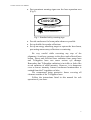
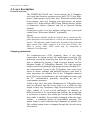
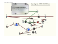
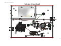
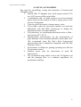
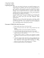
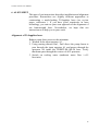
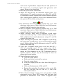
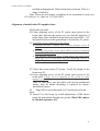
Mode-Locked Femtosecond
Titanium:Sapphire Laser
MODEL Trestles–100-F4
MANUAL
4119 Twilight Ridge, San Diego, CA 92130 USA Tel::858.876.3133 Fax::858.630.2376
Trestles-100-F4 User Manual
TABLE OF CONTENTS
1.
2.
3.
4.
5.
6.
7.
8.
Introduction
Laser safety
Laser description
List of accessories
Installation
Alignment
Day-to-day operation
Possible problems
2
Trestles-100-F4 User Manual
1. INTRODUCTION
Ti:Sapphire
Titanium-doped sapphire (Ti:Sapphire) is a solid state laser
medium capable of tunable laser operation over broad range of
near infrared (IR) wave lengths. Because of its broad absorption
band in blue and green, energy for lasing process can be
supplied by standard continuous wave (CW) argon ion laser or
CW 532 nm, high-power, diode-pumped solid state laser as
opposed to an electrical discharge or flash lamp that supplies
broad band excitation.
Solid-state mode-locked lasers produce femtosecond light
pulses using Kerr lens mode-locking (KLM) principle of
operation and continuous wave pumping sources. KLM
principle combines self-focusing nonlinear optical effect and
aperture effect together to reach the shortest optical pulses.
This Kerr self-focusing effect leads to slight changes in the
spatial intensity profile of the resonator mode in laser
oscillators. As a consequence, by introducing an intracavity
aperture, a power-dependent loss can be created. Owing to the
quasi-instantaneous
response
of
nonresonant
Kerr
nonlinearities, the amplitude modulation induced by selffocusing is able to simulate ultrafast saturable-absorber action
and support pulse formation down to the femtosecond regime
in solid-state lasers that have long gain-relaxation times. The
gain bandwidth of solid state laser materials such as
Ti:Sapphire extends over >200nm and has the potential for
supporting pulses of less than 10fs. The pulse duration from
these lasers is determined by critical interplay between
intracavity self-phase modulation in media, and negative group
delay dispersion.
Trestles-100-F4 femtosecond laser head contains the
Ti:Sapphire rod, the optics that form the resonator cavity, and
CW 532 nm, high-power, diode-pumped solid state laser.
Del Mar Photonics guarantees that provided laser was
tested and it is suitable for the Kerr lens mode-locked
operation. On the one hand, the laser installation without the
help of the manufacturer requires some experience of the user
in laser physics. But on the other hand, by working with our
laser you will gain experience in ultrafast laser technology.
3
Trestles-100-F4 User Manual
2. LASER SAFETY
Trestles-100-F4 and its pump laser are Class IV –highpower lasers, whose beams are, by definition, safety
and fire hazards. Take precautions to prevent exposure
to direct and reflected beams. Diffuse as well as secular
reflections cause severe skin or eye damage.
TRESTLES-100-F4 laser emits CW and pulsed
infrared radiation, it is extremely dangerous to the eye.
Infrared radiation passes easily through the cornea,
which focuses it on the retina, where it can cause
instantaneous permanent damage.
Precautions for the safe operation
of Class IV Power lasers
• Wear protective eyewear at all times; selection depends on
the wavelength and intensity of the radiation, the conditions
of use, and the visual function required. Protective eyewear
vendors are listed in the Laser Focus World, Laser
Optronics, and Photonics Spectra buyer’s guides. Please
use safety instructions of your pump laser and follow their
recommendations in your work.
• Maintain a high ambient light level in the laser operation
area. This keeps the pupil constricted, thus reducing the
possibility of eye damage
• Keep the protective cover on the laser at all times.
• Avoid looking at the output beam; even diffuse reflections
are hazardous. Keep all beams below eye level always.
Never look in the plane of propagation of the beams.
• Avoid wearing jewelry or other objects that may reflect or
scatter the beam while using the laser.
• Use an infrared detector or energy detector to verify that the
laser beam is off before working in front of the laser.
• Operate the laser at lowest beam intensity possible, given
the requirements of the application.
• Expand the beam whenever possible to reduce beam power
density.
• Avoid blocking the output beams or its reflection with any
part of the body.
• Establish a controlled access area for laser operation. Limit
to those trained in the principles of laser safety.
4
Trestles-100-F4 User Manual
• Post prominent warning signs near the laser operation area
(Fig.1).
DANGER
VISIBLE AND /OR INVISIBLE LASER RADIATION
AVOID EYE OR SKIN EXPOSURE TO DIRECT
OR SCATTERED RADIATION
CLASS IV LASER PRODUCT
Fig.1. Standard safety warning sign
• Provide enclosures for beam paths whenever possible.
• Set up shields for secular reflections.
• Set up an energy absorbing target to capture the laser beam,
preventing unnecessary reflections or scattering.
Be very careful while executing any step of the
alignment. Avoid any exposure to the direct and reflected laser
beams. Direct and reflected laser radiation from pump laser
and Ti:Sapphire laser can cause serious eye damage.
Remember that Ti:Sapphire radiation is invisible or looks like
as red radiation of small intensity. However, it is dangerous
even at lowest intensity. Intense incoherent luminescence is
emitted from the Ti:sapphire rod also.
We recommend using protective boxes covering all
elements outside of the Ti:Sapphire laser.
Follow the instructions listed in this manual for safe
operation of your laser.
5
Trestles-100-F4 User Manual
3. Laser description
General overview
The TRESTLES-100-F4 laser head contains the Ti:Sapphire
rod, optics that form the resonator cavity and CW 532 nm, highpower, diode-pumped solid state laser. Elements include pump
beam mirrors, laser rod, focusing lens and mirrors, an output
coupler (OC), high reflector (HR), beam folding mirrors, prisms
as dispersion control elements and slit as spectral turning
element.
Connections to the cover box include cooling water, power and
control from “Electronics Module” (optionally).
Option:
The Electronics module enclosed with the laser consists of the
pulse detection circuit and driver circuits for electromechanical
starter. All indicators and controls are located on the front and
upper panel. One cable connects it to cover box of laser, the
other is power cable. BNC cable may be connected to
customer’s oscilloscope.
Pumping optimization
For continuous-wave (CW) pumping, there is one basic
requirement for lasing action: the unsaturated round-trip CW
gain must exceed the round trip loss from all sources. The CW
gain is obtained by having a high inversion density and an
adequate length of Ti:Sapphire material. The high inversion
density comes from having a high pump intensity and high Ti3+
ion concentration. Losses in the Ti:Sapphire laser come from
losses in mirror coatings and polished surfaces, and what is
more important, the residual loss in the Ti:Sapphire material
itself. This loss is proportional to the rod length and varies with
the Ti3+ concentration, generally increasing as the Ti3+
concentration increases.
Unlike a dye laser, the pump illumination in Ti:Sapphire laser
must be collinear with the cavity mode over a relatively long
length of laser rod. Continuous, high inversion density over the
entire volume of a rod several millimeters in diameter is
difficult to achieve. To circumvent this problem, the pump light
is focused to a narrow line within the rod and the oscillating
laser mode is similarly focused and overlapped within the same
volume – a technique known as longitudinal pumping. The
output beam is then collimated and expanded to normal size.
The residual pump beam is dumped through the second cavity
focus mirror.
6
Trestles-100-F4 User Manual
TRESTLES-100-F4 laser description
Pump laser
Due to broad absorption band in blue and green, energy for
lasing process can be supplied by standard continuous wave
(CW) argon ion laser or CW 532 nm, high-power, diodepumped solid state lasers. It is very important to note that pump
laser should work in TEM00 mode.
For pumping TRESTLES-100-F4 laser a pump laser operating
in TEM00 transverse mode regime with output power 3 - 5 Watts
should be used. CW 532 nm, high-power, diode-pumped solid
state laser from Laser Quantum is used in TRESTLES-100-F4.
This laser generates a near-diffraction limited, highly stable
beam at 532nm. Capable of delivering >3W of power, this laser
is the most compact laser in its class. It has highly sophisticated
digital electronics.
Specifications
Power
Wavelength
Beam size
Transverse mode
Divergence
M2
Power stability (rms)
Noise (1Hz-6MHz - rms)
Polarisation ratio
>4W
532 nm
2.5 mm
TEMoo
< 0.4 mrad
< 1.1
< 1.0 %
< 0.5 %
100:1
The folded cavity
Del Mar Photonics modeled, analyzed and optimized the
cavity design for optimum performance in minimal space. The
result was a 10 mirrors folded cavity (Fig.2). This scheme
incorporates 10-mirror cavity (M1, M2, M3, M4, M5, M6, M7,
M8, M9, OC), Ti:Sapphire crystal (TiS), lens for focusing of
pump radiation (L), two prisms (P1 and P2) and slit (S).
In folded cavities where astigmatism is not eliminated, output
beams are elliptical and hard to focus. But by carefully choosing
the angles of the cavity focus mirrors and rod length,
astigmatism in TRESTLES-100-F4 output beam is virtually
eliminated.
7
Trestles-100-F4 User Manual
Wavelength turning characteristics
Because the Ti:Sapphire rod is birefringent, uninterrupted
turning is achieved when the c – axis of the rods is aligned
coplanar with the polarization of electric field within the cavity.
Since the Ti:Sapphire rod and prism surfaces represent a total of
six Brewster's angle surfaces, the polarization within the cavity
is largely determined by the orientation of these surfaces.
Furthermore, cavity losses are minimized and tuning is
optimized when all these surfaces are accurately aligned at
Brewster's angle. The laser uses a proprietary Ti:Sapphire rod
holder that orients the rod surfaces at Brewster's angle and
allows the “c” axis of the rod to be aligned coplanar to the
electric field vector. This technique compensates for
unavoidable errors in rod orientation that occur when the rod is
cut and polished. Wavelength tuning range of the TRESTLES100-F4 laser is 730 nm to 860 nm with 10-25 nм FWHM.
Wavelength selection
The femtosecond laser TRESTLES-100-F4 is wavelength
turned using a prism sequence and the slit. This prism sequence
provides a region in cavity where the wavelengths are spatially
spread. A variable slit is located in this dispersed beam. The
output wavelength is turned by changing the position of the slit
in horizontal plane. The width of the slit can also be changed so
that the bandwidth (and, hence, the temporal width) of the
output pulse can be varied. This simple, straight-forward
method covers the entire Ti:Sapphire range for ultrashort pulses.
8
Trestles-100-F4 User Manual
Key diagram of TIF-100-4W laser
CW 532 nm, high-power,
diode-pumped solid state laser
Pm1
М8
OC
A3
A2
М7
Pm2
A1
L
М1
TiS
S
М2
М9
P2
М3
P1
A4
М4
М5
A5
М6
Fig. 2
9
Trestles-100-F4 User Manual
10
Trestles-100-F4 User Manual
Scheme of laser head.
11
Trestles-100-F4 User Manual
Fig.3
12
Trestles-100-F4 User Manual
Pulse width selection
The pulse width turning characteristics of the Ti:Sapphire laser
are influenced by two factors: those inherent in the Ti:Sapphire
material itself and those from cavity parameters. While we
cannot readily modify the Ti:Sapphire material to change pulse
width, we can modify the net group velocity dispersion (GVD).
The optical components in the laser cavity introduce positive
GVD and cause pulse spreading. Further pulse spreading causes
self-Phase modulation (SPM) in the Ti:Sapphire rod, which
results from the interaction of the short optical pulse with the
nonlinear refractive index. In order to obtain stable short output
pulses, these effects must be compensated with negative GVD.
Prism pairs are used to produce a net negative intracavity GVD
in fs system. This allows the system to produce sub 50 fs near
transform limited pulses over most of wave length regime.
The scheme of laser depicted on the Fig.2. Laser consists of the
following optical elements for the basic configuration:
1.5 mm long Ti-doped sapphire crystal (TiS);
2. Dielectric mirrors M1, M2, M3, M4, M5, M6 M7, M8, M9 with
high reflection (>99,5%). M1, M2 – have high reflection for working
wavelength and transparent for laser pumping radiation, radius of
curvature is 100 mm;
M3, M4, M5, M6, M7, M8, M9- high reflectors for working
wavelength, flat mirrors;
OC - output coupler;
Pm1, Pm2 – pump routing flat mirror.
3. L - lens for focusing of pumping radiation, focal length is
F=80 mm.
4. P1, P2 - Brewster angle prisms at 800 nm
5. A1, A2, A3, A4, A5 – aligning apertures.
13
Trestles-100-F4 User Manual
4. LIST OF ACCESSORIES
You need for assembling, testing and operation of femtosecond
Ti:Sapphire laser:
1. Optical table. Ti:Sapphire laser itself requires about 0.530
m x 0,430 m area of the optical table.
2. A photodiode with >10 mm2 sensitive area or low-inertial
power meter for fast control of relative output power in the
process of alignment.
3. A power meter for control of output power value.
4. If you didn’t order the electronics module you need fast
photodiode with 400 MHz oscilloscope to display the
temporal structure of output radiation.
5. Two polarizers, we recommend polarization cubs or Glan laser prisms (PC1, PC2).
6. Interferometric autocorrelator for the measurement of
pulse duration. Time resolution should be better than 10 fs.
(We recommend using Del Mar’s Reef femtosecond
autocorrelator that is completely compatible with Del Mar
Photonics lasers.)
7. Spectrometer or diffractive grating operating near 800 nm
for spectrum control.
8. Infrared sensor card for observation of weak IR
luminescence.
9. We recommend using chiller to keep the Ti:Sapphire rod
and the pumping laser at a constant temperature for
performance stability.
14
Trestles-100-F4 User Manual
5. INSTALLATION
Unpacking your laser
Your laser was packed with great care and all containers were
inspected prior to shipment: the laser left Del Mar Photonics in
good condition. Upon receipt of your laser, immediately inspect
the outside of the shipping containers. If there is any major
damage, such as holes in the box or cracked wooden frame
members, insists on that a representative of the carrier should be
present when you unpack the contents.
Carefully inspect your laser as you unpack it. If you notice any
damage, such as dents, scratches or broken knobs immediately
notify the carrier and your Del Mar Photonics Sales
representative.
Open the cover of laser head and remove the bags which
covering the elements of laser and fixing elements which are
used for transport. Do it very carefully, try not to misalign the
laser, and damage mirrors during this procedure.
Placement of TRESTLES-100-F4 laser head.
1. Hook up the water hoses to the laser head.
2. Secure the laser head to the table with provided four foot
clamps.
The clamps slide over the lower portion of each foot.
3. Verify the height adjust locking nuts on the fit are tight.
4. Connect the slit control buttons to the laser head. Tap power
supply into power line (options).
5. Connect Starter button or connect the Electronic module
(optionally) to the laser head. Tap power supply in to power
line
6. Verify the output of the pump laser meets specifications for
power and mode quality. (For pumping TRESTLES-100-F4
laser should be used pump laser operating in TEM00
transverse mode regime with output power >3 Watts).
7. Reduce pump laser power to the minimum.
15
Trestles-100-F4 User Manual
6. ALIGNMENT
This part of our instructions describes installation and alignment
procedure. Researchers use slightly different approaches to
constructing a mode-locking Ti:Sapphire laser (see review
paper, references ). If you have good experience in laser
technology, you can use your own approach to the alignment of
our femtosecond laser. Nevertheless, we hope that our
instructions will help you in your work.
Alignment of Ti:Sapphire laser.
Reduce pump laser power to the minimum.
1. Wrench in the input aperture A1.
2. Using routing mirrors Pm1, Pm2 direct the pump beam to
pass through the input aperture A1 and passes through the
apertures A4 inside the TRESTLES-100-F4 laser. Verify
that beam pass through the centers of all 2 apertures.
3. Switch on cooling water (moderate water flow >=0.5
liter/min).
16
Trestles-100-F4 User Manual
It is not necessary to follow the italicized instructions fore
the first alignment. You should only carry out these procedures
in case of complete laser misalignment under severe
transportation conditions. Please, follow the bold-typed
instructions.
4. Close the shutter of the pump laser.
5. Remove M1 and M2 mirrors with holders from their mounts.
6. Remove focusing lens L with the draw-tube from mount.
1. Screw for aligning crystal position on optical axis. 2. Screw for transverse aligning. 3. Screw for
aligning Brewster angle. 4. Screw for aligning crystallographic axis orientation. 5. Spring
6. Fixing screw
Fig.4
7. Remove the crystal with the crystal holder (fig. 4).
• Remove two vertical springs from the holder using a
metallic hook (metallic hook may be easily made from
paper clip) or thin-flat-nose pliers.
• Loose but not remove four clamping screws, two on
each side of the crystal mount.
• Remove the crystal with crystal holder.
8. Open pump shutter.
9. As you can see there is a scratch passing under the elements
from Pm2 to M2 direction. Move the AA (AA-additional
aperture) so the mark on lower part aperture coincides with
scratch on the table top.
10. Direct the pump beam parallel to the scratch passing
through the center of AA and A1 aperture, using mirrors
Pm1, Pm2.
17
Trestles-100-F4 User Manual
11. Install the focusing lens with a draw-tube back to the lens
mount.
12. Place AA near M2 so the mark on the aperture holder
coincides with scratch on the table top.
13. Verify that the center of the beam spot on AA is still on the
center of AA
• If the centers do not coincide in vertical plane then use
the vertical lens adjusting screw to align the lens. (Some
laser systems have lens holders without vertical aligning
screw. If so, then loose, but don’t remove, fixing screws.
Align the position of the lens and then fix the screws.)
• If the centers are not coinciding in horizontal plane then
loose the screws that clamp the lens holding stage to the
translation stage and move the lens holding stage in
perpendicular to pump beam direction to align the lens
and then fix the screws.
14. Close the pump beam shutter.
15. Install the M1 mirror with the holder to its mount.
16. Remove a beam stopper beyond M2
17. Insert the PC2 in the pump beam beyond the M2 mirror
mount. Place the target (piece of paper) beyond the PC2.
Align the PC2 for a “dark field”.
18. Install and align the crystal
• Close pump shutter.
• Mount the crystal holder to its mount.
• Tighten two vertical springs.
• Open pump shutter.
• Verify that the beam is passing through the center of the
crystal.
• Set up approximately Brewster angle by the angle
control of crystal, observing green beam reflected from
the Ti: sapphire crystal entrance surface. Find position
of crystal with minimum reflection.
• Align the crystal for a dark field on the target, rotating
the crystal holder around the optical axis using the
Screw for aligning crystallographic axis orientation 4
Fig. 4.
• Close pump shutter.
• Tighten four fixing screws, two on each side of the
mount.
• Set up distance between M2 surface and entrance
surface of the crystal by the longitudinal control screw of
laser crystal stage equal to 48 mm.
19. Remove PC2 with it mount
18
Trestles-100-F4 User Manual
20. Install M2 mirror with the holder to its mount. Set up the
distance between M1 and M2 surfaces approximately to 104106 mm.
21. Place a beam stopper beyond M2.
22. Wrench off A5
23. Using adjusting screw of the P1 prism move the prism from
the beam path.
24. Open the pump shutter. Using insertion adjusting screw of
the P1 prism, remove the prism from the beam path.
Aligning M2 mirror, direct the residual part of pump beam
to the center of the M3, M4 mirror, to the center of A4, and
to the center of the mirrors M5 and M6 (verify that the beam
is parallel to the scratch on the table top, if not make it
parallel to the scratch). Verify the height of the beam
25. Aligning M6 direct beam back to the M5, M4, M3 mirrors
and through the aperture A4.
26. Wrench off all A1, A2,A3,A4 ,A5.
27. Increase pump power up to 3-4 W. Use protective goggles
for pump laser radiation.
28. Aligning the positioning of the lens. Use protective goggles
for pump laser radiation during this procedure. Remove
beam blocker, beyond M2. Translating the lens find the
position when round shape of the pump beam will abruptly
change to the oval shape. Place back the beam blocker.
29. Use IR card to see the luminescence near OC mirror.
+
reflection of M2-M3-M4-M5-M6-M5-M4-M3
M2- M1-М7- М8
reflection of M1,M7,M8 only
30. Aligning M1 mirror, direct luminescence reflected only from
the M1 – M7 – M8 to the center of the OC.
31. Verify the height of the beam with help of AA
32. Position of (+) spot is adjusted by M6 controls. The spot
should be approximately on the center of spot reflected from
M1, M7, M8 only.
33. Align OC mirror so the reflected beam return back to the
center of M8-M7 and M1.
34. If a correct alignment has been done, laser radiation should
appear after small adjustments of M6 and OC. If not then
place the additional photodiode with large aperture beyond
the OC mirror. The luminescence spot should be in the
19
Trestles-100-F4 User Manual
active area of photodiode. Adjust M6, OC and position of
M2 mirrors for a maximum signal until generation will
appear. Remove the photodiode.
35. Place the power meter in the beam.
36. Adjust the M6 and OC for maximum output power. For
optimization of Ti:sapphire output power adjust OC and M5
by horizontal controls together and vertical controls together
also. Output power should be close to the maximum when
the spots on M1 look like on the picture:
green
red
37. By small steps move M2 along the optical axis, try to find
maximum output power. Make additional small adjustments
using OC and M6 controls after each step.
38. Move Ti:sapphire crystal along the optical axis, try to find
maximum output power. Make additional small adjustments
using OC and M6 controls after each step.
39. Adjust Brewster angle using Ti:sapphire crystal angle
control in small steps. Try to reach maximum output power.
Make additional horizontal adjustments using OC and M6
controls after each step.
40. Adjust focusing lens position and Ti:sapphire crystal along
the optical axis in small steps. Try to reach maximum output
power. Make additional small adjustments using OC and M6
controls after each step.
41. Verify that Ti:sapphire output power is not less than 10% 15% of pumping power. If not, repeat steps 36-41.
Sometimes, you should repeat steps 34-39 several times
during the first alignment of the CW Ti:Sapphire laser. It
requires patience. And it may be necessary to clean the
mirrors and crystal surface.
42. Wash all mirrors in the cavity.
• Close the pump shutter.
• Wash one mirror by alcohol or acetone.
• Open the pump shutter.
• Verify the output power the value should be bigger or
the same.
• Make small adjustments of M6 and OC.
• Repeat this procedure for mirrors in the cavity M1,
M2, M3, M4, M5, M6, M7, M8 OC, L, Pm1, Pm2
and crystal surfaces.
43. Write down maximum output power and position of M2
micrometric screw. Move M2 forward and back and find
positions of micrometric screw where Ti:sapphire laser
20
Trestles-100-F4 User Manual
oscillation disappeared. Write down these positions. This is a
range of stability.
Note. There are two ranges of stability in the asymmetric cavity (see
G.Cerulla et. al., Opt.Lett. 19 (1994) 807).
Alignment of mode-locked Ti:sapphire laser.
44. Flip the slit aside.
45. Using adjusting screw of the P1 prism insert prism in the
beam path. Moving the prism you can find the position of
prism when laser oscillation begin between mirrors M6 – OC
and small fraction of this generation is deviated by P1 prism.
46. Verify the correct aligning of the prism
• Loosen but don’t remove the rotation fixation screw R
(fig. 5).
• Rotating the prism’s base plate adjust prism for minimal
deviation of the beam.
• The heights should be also 70 mm above the laser head
table top. If it is necessary use the adjusting screws to
align the prism (see the figure №5).
47. Verify that beam strikes P2 prism. Verify the height of the
beam near P2.
48. Using adjusting screw of the P2 prism insert prism in the
beam path. Verify correct aligning of the prism in same
manner as in 46.
Note. If your laser was provided with electro-mechanical
starter, then P2 holder mounting is replaced by electromechanical starter.
49. Align M9 to return deviated by P1 prism part of beam
back.
50. Insert P1 in the beam, by small adjustments of M9 mirror
reach the generation through the prisms. Block M6 mirror
by blocker (aperture A5)
21
Trestles-100-F4 User Manual
5, screw R
1, Prism
2, fixating screw
4, screw H
6, base plate
3, screw V
Fig.5. Schematic picture of prisms fixation and service
1 - prism
2 - fixating screw, ! don’t tight it with force to prevent birefringence of prism !
3 - screw V to align deviated beam in vertical plane,
4 - screw H to align reflected beams in vertical plane,
5 - screw R to fix rotation of base plate 6,
6 - prism's base plate rotating by hand.
.
51. Aligning OC and M9 find maximum output power in same
manner as in CW operation.
52. Verify that output power decreases not more than 15-25
percent lower then output power without prisms. If not,
repeat procedure from step 45. Sometimes, you should repeat
it several times during the first alignment of the CW
Ti:Sapphire laser. It requires patience.
Note. After finishing this procedures there are some check
points:
1. The spot on the M1 mirror should be look like described
in 35. If not align M9 and OC.
2. There are beams reflected from the apex of each prism.
The beams should be almost parallel to each and must be
in resonator plane (plane at 70 mm above table top of the
laser head). If not then align the prisms and M9, OC .
22
Trestles-100-F4 User Manual
53. Align P1 so that generation is passing almost through the
apex of prism. But generation should not be lost.
54. Test the output beam using fast photodiode and oscilloscope.
55. Using the position aligning screw remove P2 from the pump
beam. The generation will be lost.
56. Moving the P2 prism by your finger (thus you change the
depth of insertion of the prism) look to the result on the
oscilloscope. Then moving M2 by small steps find the place
where the pulses appear. Femtosecond pulses should appear
near the end of the region of stability. Continuous pulse train
should be observed on the oscilloscope screen in
femtosecond operation.
Note: We remind you that two regions of stability exist in
asymmetric cavity. You are moving through the stability region
having less distance between M1 and M2.
57. Manage to achieve the situation when pulses train is
observed while you hold the prism in place. Then align the
prism position screw to hold the prism in place.
58. The laser was aligned at pump power 3-4W and output
coupler 10% transmission. For higher pump level use output
couplers with higher transmission (options).
59. Measure the spectrum of Ti:Sapphire laser radiation with
help of spectrometer or diffractive grating.
60. Measure the spectrum and try to find its optimum using
control of P2 mount. You will obtain shorter pulses with
broader spectrum. Spectral bandwidth should be not less
than 10 nm at FWHM (full width half maximum) with
central wave length 800 nm. It corresponds to 100 fs.
61. Femtosecond operation starts from moving of optical
elements. Once started, femtosecond operation lasts in hours
at good pump laser stability and in stable room conditions.
When femtosecond operation disappears, start it again with
mechanical movement of P2.
62. Measure pulse duration with autocorrelator.
63. To get a tuning of output wavelength and to control a
spectral bandwidth, flip back the slit. Align the width and
position of the slit so the pulses are easily appearing at the
same spectral position where they appear without slit. Write
down the position of the prism and the slit. Then watching
the spectrum and “pulse train” move the slit to shift the pulse
spectrum to the desired region. When you will see the noise
in the train or CW portion in pulse spectrum move the prism
in the same direction. Make movements in small steps.
23
Trestles-100-F4 User Manual
Verify that laser easily starts at new position. Repeat this
steps until you reach the desired central wave length.
Note. If your laser is modified model with combined prism +
slit stage, then you can achieve spectral turning by wrenching
only one prism position screw.
If you failed to achieve the lasing after several attempts, please repeat
all the steps, including the italicized ones.
24
Trestles-100-F4 User Manual
7 DAY-TO-DAY OPERATION
1. Switch on cooling water for Ti:Sapphire laser (moderate flow).
2. Switch on the pump laser (3-5 W output).
3. Ti:Sapphire will give proper characteristics after 40 minutes.
Pump power should be stable from day to day.
4. Small adjustments of M9 and OC might be necessary in day-today operation
5. To turn off the system repeat the procedure in reverse order.
Note. Occasionally, it may be necessary to clean the optics and
surfaces of the Ti:Sapphire rod. The best method is to clean surfaces
is to first block the ion laser pump beam and then blow excess
particles from the surface. Then fold a piece of lens tissue into a pad
and clamp with a hemostat (usually provided with the ion laser). Soak
this pad with spectroscopic grade acetone or methanol, and shake off
the excess liquid. Then make one cleaning stroke only across the
surface (particles on the surface can become imbedded in the tissue
and act as an abrasive if a second stroke is made across the surface).
8 POSSIBLE PROBLEMS
1. Pump beam is not TEMoo mode.
2. Stability of pump laser is not enough.
3. Optical surfaces of laser elements are dirty.
4. The laser was aligned at pump power 3-4W and output coupler
10% transmission. For higher pump level use output couplers with higher
transmission (options).
5. You spend not enough time to reach good femtosecond pulses.
25