1
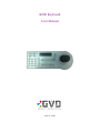
K200 Keyboard
User Manual
July 14, 2009
Index
Table of Content
Chapter 1
Open Box Listing............................................................................... 1-1
Chapter 2
Hardware Overview ........................................................................... 2-2
Chapter 3
Installation.......................................................................................... 3-1
3-1
Hardware Installation............................................................................. 3-1
3-2
Firmware Setup...................................................................................... 3-2
3-3
Installation.............................................................................................. 3-3
Chapter 4
Run Keyboard Controller................................................................... 4-1
4-1
4-2
4-3
Brief of the Keyboard Controller........................................................... 4-2
Introduction of the Keyboard Controller ............................................... 4-3
Monitor Configuration ........................................................................... 4-4
4-3-1
Add a New Monitor ................................................................... 4-5
4-3-2
Modify the Monitor Configuration ............................................ 4-6
4-3-3
Remove A Monitor..................................................................... 4-7
4-4
Camera Configuration............................................................................ 4-8
4-4-1
Add a Camera ............................................................................ 4-9
4-4-2
Edit a Camera............................................................................4-11
4-4-3
Remove a Camera .................................................................... 4-12
Chapter 5
General Operation.............................................................................. 5-1
5-1
Control Unit Selection ........................................................................... 5-2
5-1-1
Monitor Selection....................................................................... 5-2
5-1-2
Change Viewer........................................................................... 5-3
5-1-3
Change Camera.......................................................................... 5-4
5-1-4
Operation Illustration ................................................................. 5-5
5-2
Channel Operation ................................................................................. 5-6
5-2-1
Layout Change ........................................................................... 5-7
5-2-2
Image Manipulation ................................................................... 5-8
5-2-2-1 NVR Mode......................................................................... 5-8
5-2-2-2 PTZ Mode ........................................................................ 5-10
K-200 Keyboard
i
Index
Figure List
Figure 2-1 The faceplate of the K-200 keyboard....................................... 2-2
Figure 2-2 The connecting ports of the K-200 keyboard........................... 2-2
Figure 3-1 Install the K-200 keyboard....................................................... 3-1
Figure 3-2 Set up the firmware values of the keyboard............................. 3-2
Figure 4-1 Keyboard Controller................................................................. 4-3
Figure 4-2 Monitor Coding Diagram......................................................... 4-4
Figure 4-3 Add a new monitor ................................................................... 4-5
Figure 4-4 Edit a monitor........................................................................... 4-6
Figure 4-5 Remove a monitor .................................................................... 4-7
Figure 4-6 Camera Coding Diagram.......................................................... 4-8
Figure 4-7 Add a camera............................................................................ 4-9
Figure 4-8 Edit a camera...........................................................................4-11
Figure 4-9 Remove a camera ................................................................... 4-12
Figure 5-1 Change the control units........................................................... 5-2
Figure 5-2 Change the layout..................................................................... 5-7
Figure 5-3 Function keys of PTZ mode................................................... 5-10
ii
K-200 Keyboard
Chapter 1 Open Box List
Chapter 1 Open Box Listing
This package includes the following items:
K-200 Keyboard
×1
□
Power Adapter
×1
□
Connection Cable
×1
□
USB & RS-485 Converter
×1
□
User Manual & Driver CD
×1
□
Warranty Card
×1
□
RMA Card
×1
□
If your have found any missing or broken parts, please contact your GVD Sales Rep.
K-200 Keyboard
1-1
Chapter 2 Hardware Overview
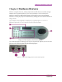
Chapter 2 Hardware Overview
K200 is a complete-function, desktop keyboard controller that successfully manages
multiple HD NVRs and monitors, use the keys promptly to select cameras and
monitors, control live and playback images, and operate presets, tour and pattern
functions. Twisting the joystick could effortlessly manage the PTZ function instead of
using a mouse.
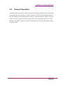
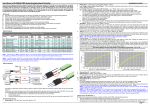
The faceplate of the keyboard is composed of (1) function keys, (2) LCD, (3)
Indicator Light, and (4) 3-axis joystick. See the following figure:
Figure 2-1 The faceplate of the K-200 keyboard
The connection ports, including (5) two device ports and (6) a power port, are located
in the rear side of the keyboard. See the following figure:
Figure 2-2 The connecting ports of the K-200 keyboard
2-2
K-200 Keyboard
Chapter 3 Installation
Chapter 3 Installation
3-1
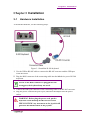
Hardware Installation
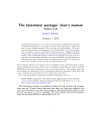
To install the hardware, see the following steps:
Figure 3-1 Install the K-200 keyboard
1. Use the USB to RS-485 cable to connect the RS-485 converter and the USB port
of the HD NVR.
2. Plug the RJ45 connector of the connecting cable into the left device port of K-200
keyboard.
NOTE: If the RJ45 connector is plugged into the
wrong port, the keyboard may not work.
3. Connect the DB-9 pin connector of the connecting cable to the RS-485 converter.
4. Plug the power cord into the power port, and insert the adapter into the power
socket.
WARNING: Before plug the power cord, put the
keyboard on the desktop and DO NOT TOUCH
THE JOYSTICK. Any movement on the joystick will
generates the initiation bias of the joystick.
K-200 Keyboard
3-1
Chapter 3 Installation
3-2
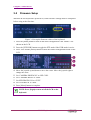
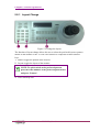
Firmware Setup
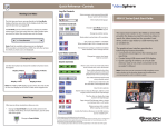
When the K-200 keyboard is powered on, some firmware settings must be completed
before using at the first time.
Figure 3-2 Set up the firmware values of the keyboard
1. Press the [Menu] button to turn off the menu configuration if the ‘MENU’ was
shown on the LCD.
2. Press the [PTZ/NVR] button to toggle the PTZ mode if the NVR mode is active.
3. Press ‘999’ and the [Menu] button to show the camera configuration menu on the
LCD.
4. Move the joystick up and down to move the cursor. Move the joystick right to
change the value.
5. Set ‘CAMERA PROTOCOL’ to ‘PELCOD’.
6. Set ‘CAMERA BAUD’ to ‘9600’.
7. Set NVR PROTOCOL to “GVD”.
8. Set ‘NVR BAUD’ to ‘9600’.
9. Press [Menu] button to complete.
NOTE: Press [Light] to turn on/off the LCD on the
keyboard.
3-2
K-200 Keyboard
Chapter 3 Installation
3-3
Installation
The keyboard application (Keyboard Controller) will be installed automatically when
the HD NVR Manager has been set up. Before running the application, the hardware
driver should be installed in advance. See the following steps:
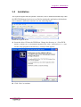
Install the required driver
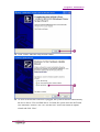
1. Insert the driver CD into the DVD Rom. Change the directory to ‘{Your DVD-
ROM }:\UPort1110_1130\Software\Windows XP_2003_Vista\x86\Ver 1.5’, and
run the setup program in the directory. A setup wizard appears.
2. Click ‘Next’ to continue.
K-200 Keyboard
3-3
Chapter 3 Installation
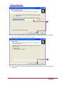
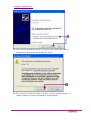
3. The setup wizard prompts the installed directory. Change the path of the installed
directory if necessary. Click ‘Next’ to continue.
4. Click ‘Install’ to start the installation procedure. Wait until the procedure has been
completed.
3-4
K-200 Keyboard
Chapter 3 Installation
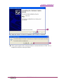
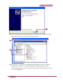
5. Click ’Finish’ when the setup wizard is done.
6. As soon as the RS-485 converter is plugged, the system will detect automatically
the device driver. If no available driver is found, the system activates the Found
New Hardware wizard. Click ‘No, not this time’ item in the hardware update
wizard and click ‘Next’.
K-200 Keyboard
3-5
Chapter 3 Installation
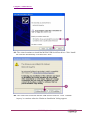
7. The wizard will install the UPort 1130 driver. Click ‘Install the software
automatically’ item in the wizard and click ‘Next’.
8. The wizard will search the UPort 1130 driver. Click ’Continue Anyway’ to
continue when the ‘Hardware Installation’ dialog appears.
3-6
K-200 Keyboard
Chapter 3 Installation
9. When the UPort 1130 driver is installed, click ‘Finish’ to continue.
10. The system requires the restart procedure to activate the driver. Click ‘No’ to
temporarily stop the restart procedure.
K-200 Keyboard
3-7
Chapter 3 Installation
11. The wizard continues to install the MOXA USB Serial Port driver. Click ‘Install
the software automatically’ item and click ‘Next’.
12. The wizard will search the MOXA USB Serial Port driver. Click ’Continue
Anyway’ to continue when the ‘Hardware Installation’ dialog appears.
3-8
K-200 Keyboard
Chapter 3 Installation
13. When the MOXA USB Serial Port driver is installed, click ‘Finish’ to continue.
When the wizard is done, DO NOT restart the system.
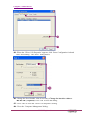
14. Click Start->Control Panel->Administrative Management Tools->Computer
Management. When the ‘Computer Management’ dialog appears, click the
‘Device Management’ in the tree panel on the left hand side. Double click ‘UPort
1130’ in the right panel.
K-200 Keyboard
3-9
Chapter 3 Installation
15. When the ‘UPort 1130 Properties’ appears, click ‘Ports Configuration’ tab and
click ‘Port Setting’. The ‘Port 1’ dialog shows.
16. Change the Port Number value if necessary. Change the interface value to
‘RS-485 2W’ (required). Click ‘OK’ to close the dialog.
17. Close ‘OK’ to close the ‘UPort 1130 Properties’ dialog.
18. Close the ‘Computer Management’ dialog.
3-10
K-200 Keyboard
Chapter 3 Installation
NOTE: Before running the Keyboard Controller, the
user needs to import the license file. Refer to the HD
NVR User manual for more details about the
authority process.
When the RS-485 converter is plugged to other USB
port again, the system will re-install the drivers. The
associated COM port number will be changed as
well. Put the new COM port on a note for the
modification of the Keyboard Controller.
K-200 Keyboard
3-11
Chapter 4 Run Keyboard Controller
Chapter 4 Run Keyboard Controller
The keyboard controller is the control application of the K-200 keyboard. The K200
keyboard may not work when the keyboard controller is inactive. When the
Windows® is logged on, the keyboard controller icon will shows in the Windows tray.
The Keyboard Controller includes three main configurations: connection port setup,
camera setup, and monitor setup. See the following description.
K-200 Keyboard
4-1
Chapter 4 Run Keyboard Controller
4-1
Brief of the Keyboard Controller
Keyboard Controller is the management application between the K200 Keyboard and
the connecting NVR/Control Workstation. When the Keyboard Controller is running,
the user can quickly change the active devices for operations by pressing the keys of
the K200 keyboard.
Before using the Keyboard Controller, the user needs to complete the device
configuration. The device configuration encodes all connecting devices, and the
Keyboard controller can rapidly find the corresponding devices for following
operations. There are three types of device configuration:
Monitor: Keyboard Controller encodes all monitors by the associated IP address of
the connecting NVR/Control Workstation and the display order. Press the number key
and then the [Mon] key on the keyboard to set the specific monitor active. If the [Mon]
key is pressed simply, all monitors will show the code number on the screen.
Viewer: Keyboard Controller encodes all viewers of the layout or pattern by the
top-down and left-right rule. Press the number key and then the [View] key on the
keyboard to set the specific viewer active. Simply press the [View] key, and all
viewers will show the code number on the screen.
Camera: Keyboard Controller encodes all cameras by the IP address of the
connecting NVR and the channel ID in the configuration mode of the CMS and CSL
application. Press the number key and then the [Cam] key on the keyboard to play the
live image of the specific camera in the active viewer. Simply press the [Cam] key,
and the viewers that play the images of the associated camera will show the code
number.
4-2
K-200 Keyboard
Chapter 4 Run Keyboard Controller
4-2
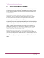
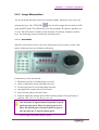
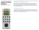
Introduction of the Keyboard Controller
The keyboard controller includes four function buttons and drop-down menu
configuration items. To change the values of configuration items, the keyboard
controller must be stopped first. See the following descriptions.
1.
2.
3.
4.
5.
Figure 4-1 Keyboard Controller
Running button: run the Keyboard Controller.
Stop button: stop the keyboard controller.
Monitor button: add or edit the monitors the Control Workstation connect to.
Camera button: add or edit the connecting cameras.
Keyboard Model: change the keyboard model.
6. Com Port: change the connection port (must be consistent with the hardware
setting of the RS-485 converter.)
7. Connection Type: change the connection type.
K-200 Keyboard
4-3
Chapter 4 Run Keyboard Controller
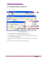
4-3
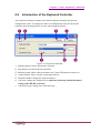
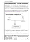
Monitor Configuration
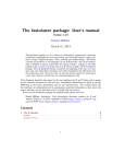
Monitor configuration is for the encoding task of all connecting monitors. All
connecting monitors are added to the monitor listing, and the monitor is encoded by
the IP address of the connecting NVR/Control Workstation and the display order. See
the following demonstration for details.
Figure 4-2 Monitor Coding Diagram
Suppose two monitors have connected to NVR D (IP address: 192.168.1.12), and the
index of the 1st monitor is ‘8’ in the listing. The user can press ‘8’ and the [Mon] key
on the keyboard to switch to the 1st monitor of NVR D.
The monitor configuration allows the user to add, edit, or remove the connecting
monitors. To run the monitor configuration mode in the Keyboard Controller, see the
following section:
4-4
K-200 Keyboard
Chapter 4 Run Keyboard Controller
4-3-1 Add a New Monitor
1.
2.
3.
4.
5.
Figure 4-3 Add a new monitor
Click the stop button to stop the Keyboard Controller.
Click ‘Monitor’, and a ‘Monitor Configuration’ dialog appears.
Click a blank cell in the listing, and click ‘Edit’. (Or double click a blank cell in
the monitor listing directly). An ‘Add Monitor’ dialog appears.
Input the physical IP address and the monitor ID (the screen order), and click
‘OK’.
Click ‘OK’ to close the ‘Monitor Configuration’ dialog.
NOTE: All connecting NVRs/ Control Workstations
must be in the same network segment.
K-200 Keyboard
4-5
Chapter 4 Run Keyboard Controller
4-3-2 Modify the Monitor Configuration
1.
2.
3.
4.
5.
4-6
Figure 4-4 Edit a monitor
Click the stop button to stop the Keyboard Controller.
Click ‘Monitor’, and a ‘Monitor Configuration’ dialog appears.
Click the IP address of the target monitor in the monitor listing, and click ‘Edit’.
The ‘Add Monitor’ dialog appears.
Change the physical IP address and the monitor ID (the screen order), and click
‘OK’.
Click ‘OK’ to close the ‘Monitor Configuration’ dialog.
K-200 Keyboard
Chapter 4 Run Keyboard Controller
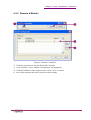
4-3-3 Remove A Monitor
1.
2.
3.
4.
Figure 4-5 Remove a monitor
Click the stop button to stop the Keyboard Controller.
Click ‘Monitor’, and a ‘Monitor Configuration’ dialog appears.
Click the IP address of the target monitor. Click ‘Clear’ to remove.
The selected monitor has been removed from the listing.
K-200 Keyboard
4-7
Chapter 4 Run Keyboard Controller
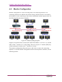
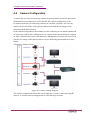
4-4
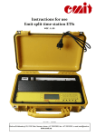
Camera Configuration
To find a specific camera from many cameras is difficult when several NVRs/Control
Workstations have connected to each other. By the camera configuration of the
Keyboard Controller, all connecting cameras are encoded. Therefore, the user can
quickly retrieve the index of the specific camera and recall the live image of the
camera by the K200 keyboard.
In the camera configuration, the IP address of the connecting NVR and the channel ID
of camera are used for the coding item. Every camera in the camera listing is assigned
an index. When the user presses the index key and then the [Cam] key, the viewer will
play the live image of the desired camera. See the following demonstration for more
details.
Figure 4-6 Camera Coding Diagram
The camera configuration allows the user to add, edit, or remove the connecting IP
camera. To run the camera configuration, see the following sections.
4-8
K-200 Keyboard
Chapter 4 Run Keyboard Controller
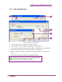
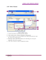
4-4-1 Add a Camera
1.
2.
3.
4.
Figure 4-7 Add a camera
Click the stop button to stop the Keyboard Controller.
Click ‘Camera’, and a ‘Camera Configuration’ dialog appears.
Click a blank cell in the camera listing, and click ‘Edit’. (Or double click a blank
cell in the camera listing.) The ‘Add Camera’ dialog appears.
Set the IP address of the connecting NVR, the connecting port, and the given
channel ID in the configuration mode of CSL. Click ‘OK’ to continue.
NOTE: To find out the channel ID, the user should run
the CSL application and change to the configuration
mode. Click the desired camera from the device tree
and find out the value of the channel ID.
K-200 Keyboard
4-9
Chapter 4 Run Keyboard Controller
NOTE: The IP address of the local NVR connected
by the keyboard should use ’127.0.0.1’ instead of the
physical IP address.
5. Click ‘OK’ to close the ‘Camera Configuration’ dialog.
NOTE: In the ‘Add Camera’ dialog, input the IP
address of the connecting NVR in the IP address
column. DO NOT INPUT THE IP ADDRESS OF
THE CAMERA.
4-10
K-200 Keyboard
Chapter 4 Run Keyboard Controller
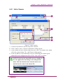
4-4-2 Edit a Camera
1.
2.
3.
4.
5.
Figure 4-8 Edit a camera
Click the stop button to stop the Keyboard Controller.
Click ‘Camera’, and a ‘Camera Configuration’ dialog appears.
Click the IP address of the desired channel in the camera listing, and click ‘Edit’.
The ‘Add Camera’ dialog appears.
Modify the values of HD NVR IP address, the connecting port, or the given
channel ID. Click ‘OK’ to continue.
Click ‘OK’ to close the ‘Camera Configuration’ dialog.
K-200 Keyboard
4-11
Chapter 4 Run Keyboard Controller
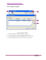
4-4-3 Remove a Camera
1.
2.
3.
4.
Figure 4-9 Remove a camera
Click the stop button to stop the Keyboard Controller.
Click ‘Camera’, and a ‘Camera Configuration’ dialog appears.
Click the IP address of the target channel and click ‘Clear’ to remove.
The selected channel has been removed from the camera listing.
4-12
K-200 Keyboard
Chapter 5 General Operation
Chapter 5 General Operation
This chapter introduces the general operation of the K-200 keyboard. The operation
includes two parts: control unit selection and image operation. Section 5-1 describes
how to switch the control units, like monitor, viewer, and camera. Section 5-2
describes how to use the function keys for channel operation, and how to use the
keyboard for the PTZ camera.
.
K-200 Keyboard
5-1
Chapter 5 General Operation
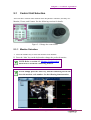
5-1
Control Unit Selection
There are three control units defined in the Keyboard Controller, and they are:
Monitor, Viewer, and Camera. See the following sections for details.
Figure 5-1 Change the control units
5-1-1 Monitor Selection
1. Press the number key to enter the monitor code number.
2. Press the ‘Mon’ key on the keyboard to change the preferred monitor.
NOTE: Refer to section 4-3 ‘Monitor Configuration’
about how to encode the connecting monitor.
NOTE: Simply press the ‘Mon’ key, and the connecting screen will
show the monitor code number. See the following demonstration.
5-2
K-200 Keyboard
Chapter 5 General Operation
5-1-2 Change Viewer
1. Press the number key to enter the viewer code number. The viewer order is based
on the rule of ‘top-down first, left-right next’.
2. Press the ‘View’ key on the keyboard to change the preferred viewer. The selected
viewer will become active.
NOTE: Simply press the ‘View’ key, and the pattern will show the code
numbers on all viewers. See the following demonstration.
K-200 Keyboard
5-3
Chapter 5 General Operation
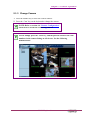
5-1-3 Change Camera
1. Press the number key to enter the camera number.
2. Press the ‘Cam’ key on the keyboard to change the camera.
NOTE: Refer to section 4-4 ‘Camera Configuration’
about how to encode the connecting camera.
NOTE: Simply press the ‘Cam’ key, and the pattern will show the code
numbers in the camera listing on all viewers. See the following
demonstration.
5-4
K-200 Keyboard
Chapter 5 General Operation
5-1-4 Operation Illustration
The following examples illustrate how to set the focus to the desired device.
Ex. 1 - Set the third viewer of the fifth monitor active.
To set the third viewer of the fifth monitor active by the keyboard, see the following
setps:
1. Press ‘5 and ‘Mon’ on the keyboard.
2. Press ‘3’ and ‘View’ on the keyboard.
3. The viewer has gotten the focus and kept in the memory of the Keyboard
Controller.
Ex. 2 – Show the image of the 11th camera.
To show the image of the 11th camera by the keyboard, see the following steps:
1. Press the ‘Cam’ key and press ‘11’ on the keyboard.
2. The active viewer shows the live image of the 11th camera.
NOTE: To combine the steps in the sample 1 & 2, the
user may play the image of the specific camera on
the specific viewer of the specific monitor.
NOTE: Keyboard Controller stores the last Monitor
index and the last viewer index for user’s recall. If no
viewer has gotten the focus, the last viewer will play
the live image of the assigned camera. Following the
example 2, the live image of the 11th camera will be
played in the third viewer of the fifth monitor.
K-200 Keyboard
5-5
Chapter 5 General Operation
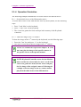
5-2
Channel Operation
A channel in the Keyboard Controller means the image generated from the connecting
camera, like the general camera or the PTZ camera, or the associated image function,
like sub channel. The keyboard has two modes: NVR mode and PTZ mode. The NVR
mode is for the operation of general camera and associated image function (ex. Sub
channel), and the PTZ mode is for the PTZ functions only. See the following sections
for more details.
5-6
K-200 Keyboard
Chapter 5 General Operation
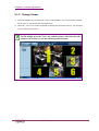
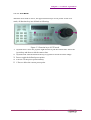
5-2-1 Layout Change
Figure 5-2 Change the layout
The function of layout change allows the user to select the preferred layout or pattern
shown on the monitor or the TV wall. The function is composed of three function
keys:
1. Pattern: toggle the pattern in the tour list
2. Layout: toggle the layout of the monitor
NOTE: To quick switch to the preferred pattern,
press the order number of the preferred pattern first
and press ‘Pattern’.
3. Tour: start/stop tour.
K-200 Keyboard
5-7
Chapter 5 General Operation
5-2-2 Image Manipulation
The K-200 Keyboard allows the user to run the ordinary functions of the viewer by
pressing the keys. The ‘PTZ/NVR’ (
) key is used to toggle the two modes: NVR
mode and PTZ mode. The NVR mode is for non-mechanic IP cameras, and there are
11 keys. The PTZ mode is mainly for the mechanic IP cameras, and there are three
keys. The following sections describe the associated keys.
5-2-2-1 NVR Mode
When the NVR mode is active, the lower function keys are on yellow. In the NVR
mode, all function keys are defined as following:
Function keys of the NVR mode:
1. Backward: play the recording image reversely.
2. Pause: temporarily stop the playing video clip.
3. Forward: play the live/recording image forward.
4. Step Backward: jump to the previous frame.
5. Step Forward: jump to the next frame
6. P.Speed: toggle the playing speed of the recording image. The speed range is
between 1/4x, 1/2x, 1x, 2x, 4x, 8x, 16x, 32x
TIP: Press the ‘P. Speed’ button repeatedly to speed
up the playing speed. When the playing speed is 32
times, the playing speed will speed down to quarter
after pressing the ‘P. Speed’ button again.
7. V. Speed: toggle the pattern display speeds
5-8
K-200 Keyboard
Chapter 5 General Operation
NOTE: For more details about pattern speed, refer
to the section 4-4-2-5 of the HD NVR User Manual.
8. Full: Toggle the 1×1 pattern and the current pattern
9. Snapshot: snapshot the image
10.M. Rec: manually recording the playing images
11.Live: play the live image
K-200 Keyboard
5-9
Chapter 5 General Operation
5-2-2-2 PTZ Mode
When the PTZ mode is active, the upper function keys are on yellow. In the PTZ
mode, all function keys are defined as following:
1.
2.
3.
4.
5.
Figure 5-3 Function keys of PTZ mode
Joystick move: move the joystick right and left to pan the camera lens. Move the
joystick up and down to tilt the camera lens.
Joystick knob: turn the knob on the top of joystick to zoom in/out the image.
Preset: toggle the defined preset points.
S-Preset: set the preset point instantly.
C-Preset: delete the current preset point.
5-10
K-200 Keyboard