1
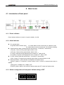
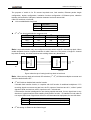
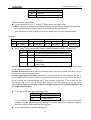
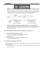
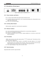
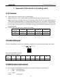
RCMS2304-120 Series
Standalone, Fiber Optic
Ethernet Multiplexer
User Manual (REV.A)
Raisecom Technology Co., Ltd.
(04/2005)
Raisecom Technology Co., Ltd
1. Cautions
Please read the following notices carefully before installing and using the device,
Raisecom does not respond to any loss that caused by violating safety notice.
RCMS2304-120 provides two types of power supply: AC and DC. When using DC
power supply, please plug the power supply connectors according to this mannual
strictly and avoid contrary connecting.
RCMS2304-120 is integrated device that has precise elements, please avoid
violent shakes and impacts, and do not disassemble or maintain the device
yourself. If it is required, please do it under the guide of our technical staff
following in the steps of anti static. Please contact us if there is any need.
There must be grounding protection for the sake of safety; do not disassemble the
device yourself, we regard it as you waiver your rights of repair guarantee.
1
Raisecom Technology Co., Ltd
Contents
1.
Cautions ............................................................................................................................................1
2.
Overview ...........................................................................................................................................4
2.1.
2.2.
2.3.
2.4.
3.
Parameters........................................................................................................................................6
3.1.
3.2.
3.3.
3.4.
3.5.
3.6.
4.
Introduction ................................................................................................................................4
Main Features ............................................................................................................................4
Number Introduction...................................................................................................................4
Dimension ..................................................................................................................................5
E1 interface technical indicator ..................................................................................................6
E1 Ethernet interface technical indicator....................................................................................6
Optical interface technical indicator............................................................................................6
Auxiliary data channel ................................................................................................................6
Power supply..............................................................................................................................6
Environment requirement...........................................................................................................7
How to use ........................................................................................................................................8
4.1. Introduction of front panel ..........................................................................................................8
4.1.1.
Power indicator ...................................................................................................................8
4.1.2.
Alarm indicator ....................................................................................................................8
4.1.3.
Switch configuration of front panel: default setting is OFF ..................................................8
4.1.4.
Function Button: buttons of default settings are all pressed out........................................11
4.1.5.
NM (network management) Interface................................................................................11
4.2. Introduction of back panel ........................................................................................................12
4.2.1.
Power Interface and Switch ..............................................................................................12
4.2.2.
Auxiliary Data Channel......................................................................................................12
4.2.3.
Ethernet interface..............................................................................................................12
4.2.4.
E1 interface.......................................................................................................................12
4.2.5.
Optical Interface................................................................................................................12
4.3. DIP-Switch of device on bottom ...............................................................................................13
5.
Installation and test .........................................................................................................................14
5.1. Installation ................................................................................................................................14
5.2. Reparation before installation...................................................................................................14
5.3. Installation Process ..................................................................................................................14
5.3.1.
Method of cable connection ..............................................................................................14
5.3.2.
Electrify .............................................................................................................................15
5.3.3.
Button usages and switch configurations ..........................................................................15
6.
Troubleshooting...............................................................................................................................16
7.
Appendix A Introduction of making cable.........................................................................................17
A.1 E1 interface ..................................................................................................................................17
A.2 Cable of Ethernet .........................................................................................................................17
2
Raisecom Technology Co., Ltd
A.3 RS232 cable of data channel .......................................................................................................17
A.3 LINK UP cable of NM interface.....................................................................................................18
3
Raisecom Technology Co., Ltd
2. Overview
2.1. Introduction
Ethernet multiplexer (RCMS2304-120) is an ideal transmission device of optical fiber for point to point
networks, middle and small capacity networks, such as wireless communication base stations, private
communication networks and switch networks. RCMS2304-120B provides 4 E1 links and 4 Ethernet
ports Fast Ethernet. It can be applied to either local management or to remote management.
2.2. Main Features
z
z
z
z
z
z
z
z
z
Adopt large scale ASIC chip, low power consumption, 4 layers PCB, and high dependability.
Full alarm indicator. Local and remote alarm can be show at one time.
Provide function with E1 branch loop-back test for easy maintain.
Provide one RS-232 auxiliary data channel.
Provide Ethernet interface with 4 ports (10/100Mbps auto-adaptive)
Support communication or insulation among Ethernet ports.
Support maximum Ethernet data frame length up to 1916 bytes
Support Ethernet full duplex IEEE802.3x and half duplex flow control of backpressure.
Support either network management (NM) or remote management. Could select NM interface
RS-232 or RS-485.
2.3. Number Introduction
Number Illustration:
RC MS 2 3 04 – 120 / AC
AC supply
4 E1 links
4 ports Ethernet
Standalone, single strand fiber, 1310nm
Switch on layer 2
Multi-service device
Company codename (Raisecom)
Note: Standalone single strand fiber Ethernet multiplexer: RCMS2304-120 should work with
4
Raisecom Technology Co., Ltd
RCMS2504-120, viz. one RCMS2304-120 should connect with one RCMS2504-120.
2.4. Dimension
z
Dimension: 320mm(W)×38mm×(H)×160mm(D)
5
Raisecom Technology Co., Ltd
3. Parameters
3.1. E1 interface technical indicator
Bit rate:
Line code:
Impedance of interface:
Electrical characteristics:
Other characteristics:
2048Kbps±50ppm
HDB3
75Ω (unbalanced BNC interface)
or 120Ω (balanced RJ-45 interface)
Comply with ITU-T G.703
Indicators, such as transfer characteristics and input jitter tolerance
comply with ITU-T G.823, G.724 etc. relevant protocols
3.2. E1 Ethernet interface technical indicator
IEEE 802.3 Ethernet
IEEE 802.3u Fast Ethernet
IEEE 802.3q
IEEE 802.3d Spanning Tree
Support maximum frame length up to 1916 Bytes
Work mode: 10/100M Auto-negotiation, Auto-MDI/MDIX and manual configuration
Flow control: IEEE 802.3x and backpressure
3.3. Optical interface technical indicator
Bit rate:
155Mbps
Fiber connecter:
SC
Optical transmission:
There are two kinds of single mode single strand fiber product: S1: 0-25KM, S2:10-50KM
3.4. Auxiliary data channel
RS232 standard
3.5. Power supply
Power Supply: DC: -48V Voltage: -36V ~ -72V
AC: 220V Voltage: 165~265V
Power consumption: ≤25W (under full load condition)
6
Raisecom Technology Co., Ltd
3.6. Environment requirement
Temperature: 0 ~ 45℃
Relative Humidity: ≤90% (25℃)
7
Raisecom Technology Co., Ltd
4. How to use
4.1. Introduction of front panel
RCMS2304-120 front panel
4.1.1. Power indicator
Power indicator (Green): If power is in good condition, it is ON
4.1.2. Alarm indicator
z
GL: general alarm
GL general alarm indicator (red):
If a certain alarm occurs at local end, GL indicator is ON.
If a certain alarm occurs at remote end, GL indicator is flashing.
z
Optical interface alarm (include local and remote end: L: local end, R: remote end)
LOS (red): If lose receiving optical signal, alarm is ON.
LOF (red): If lose receiving optical frame, alarm is ON.
E-3 (red): If optical receiving signal bit error exceeds 10-3, alarm is ON.
E-6 (yellow): If optical receiving signal bit error exceeds 10-6, alarm is ON.
z
E1 loss: (include local and remote end: L: local end, R: remote end)
LOS1~4 (red): If E1 branch lose receiving signal, alarm of relevant branch is ON
z
Ethernet indicator: (4 links indicator correspond to 4 Ethernet ports)
LNK/ACT (green): If connection is normal, alarm is ON. If receive or transmit data, alarm is
flashing.
100M (green): 100Mbps: ON, 10Mbps, OFF
FDX/COL (green): alarm is ON under full duplex mode and OFF under half duplex mode
4.1.3. Switch configuration of front panel: default setting is OFF
OFF
ON
123456
12345678
8
Raisecom Technology Co., Ltd
The purpose of switch is for E1 remote loop-back test, fault transfer, Ethernet packet length
configuration, duplex configuration, insulation function configuration of Ethernet ports, selection
between 232 and 485 of NM ports, selection between local and remote NM.
6 bits DIP-switches on left side:
z
z
1st bit: enable/disable loop-back
1st
Loop-back
OFF
Disable
ON
Enable
2nd ~4th bit: loop-back selection at remote end
2nd
3rd
4th
Loop-back
OFF
OFF
OFF
1st E1
OFF
OFF
ON
2nd E1
OFF
ON
OFF
3rd E1
OFF
ON
ON
4th E1
Note: Loop-back selection only can configure one test method: single E1 channel loop-back. When
Bit error tester
E1
Fiber
Multiplexer
Multiplexer
enable loopback function, loopback selection is valid if there is no any alarm. If single E1 channel
loop-back is testing, the other branches are working without any disturbance.
Local
E1
Remote
Figure: sketch map of setting local loop-back at local end
Note:When set loop-back at local end, DIP-switches (1st ~4th) of Ethernet multiplex at remote end
should be default state ‘OFF’.
z
z
5th bit: Enable or disable fault transfer function
If disable fault transfer function, it complies with AIS function of traditional multiplexer. If E1
receiving signals on remote end are loss, the E1 outputs of local end are all ‘1’; while if optical
signals of local end are loss, all E1 outputs are all ‘1’ at local end.
Fault transfer function is designed for user having special demands. If occur signal loss on any
direction of optical interface after enabling fault transfer function,EI interface on both side do
not output HDB3 code. Signal loss will occur at E1downterminal equipment, but not AIS alarm.
5th bit
Fault transfer function switch
OFF
Disable (comply with AIS of traditional multiplexer)
ON
Enable
6th bit: setting for Ethernet data frame length
9
Raisecom Technology Co., Ltd
6th bit
Ethernet data frame length setting
ON
1916 byte
OFF
1536 byte
8 bit DIP-Switches on right side:
z
If auto-negotiation on from 1st through 4th Ethernet port, set duplex mode.
Note: supports 10/100Mbps auto-adaptive Ethernet port and full/half duplex auto-negotiation.
Auto-negotiation fail: set duplex mode of port referring to the 4bits switches
Auto-negotiation success: working on full duplex mode foreign to 4 bits switches setting.
Definition
1st
2nd
3rd
4th
OFF
Full duplex
OFF
Full duplex
OFF
Full duplex
OFF
Full duplex
ON
Half duplex
ON
Half duplex
ON
Half duplex
ON
Half duplex
z
The 5th and 6th bit of Ethernet port: enable or disable insulation function of Ethernet port
5th
6th
Definition
OFF
OFF
1~4 can communicate each other, default setting
OFF
ON
1~4 Ethernet port isolated on local end
ON
OFF
1~4 port isolated oppositely both on two sides
(with TAG)
ON
ON
1~4 port isolated oppositely both on two sides
(without TAG)
‘Communicate’ means all users at 4 Ethernet ports of local end can communicate either each other
or with users at remote end.
“Isolated on local end” means users, at 4 Ethernet ports of local end, isolate each other; but can
communicate with users at remote end.
“isolated oppositely on two sides” means the 1st port of local end can communicate with the 1st
port of remote end, the 2nd port of local end can communicate with the 2nd port of remote end, the 3rd
port of local end can communicate with the 3rd port of remote end and the 4th port of local end can
communicate with the 4th port of remote end. Whether add TAG target or not as per users’
requirement. If enable this function, require to configure both ends to “isolated oppositely on
two sides” simultaneously.
z
7th bit: NM control RS232/485 selectable switch
7th
OFF
ON
NM control selection
RS232 control
RS485 control
If connect NM port of connection device LINKUP with computer serial port, whether use RS232
standard or RS485 standard as per the standard of computer serial port!!! Otherwise, computer
serial port cannot communicate with this equipment.
z
8th bit: enable/disable of remote management
10
Raisecom Technology Co., Ltd
8th bit
Remote management
OFF
Disable
ON
Enable
NOTE: If use NM function, should configure this bit switch before opening equipment. Ethernet
multiplexer, connecting with computer serial port by LINK UP interface (we call local end as
Ethernet multiplexer), should be configured to ‘valid local end control’, otherwise, should be
configured to ‘valid remote control’ for remote end. Therefore, two Ethernet multiplexers can be
controlled on both ends simultaneously. NM topology are illustrated as following,
NOTE: could install PC Agent software on NM computer as per users’ requirement.
Management information to Ethernet multiplexers at remote end is transmitted through the
overhead of optical signal. It will not take use of bandwidth of each port, the method of which is
out-of-band management.
4.1.4. Function Button: buttons of default settings are all pressed out.
z
z
MASK/UNMSAK shield pseudo alarm button
Press it in, shield unused E1 branch indicator (pseudo alarm)
Press it out, do not shield E1 branch indicator
RING/MUTE button
If press buttons in, alarm indicators are ON and alarm are set off.
If press buttons out, alarm is mute
4.1.5. NM (network management) Interface
Connect NM interface ‘LINK UP’ with computer serial port. Could select interface mode between
RS232 and RS485.
z
‘LINK UP’ uplink interface: RJ45 with RS232 or RS485 standard (bit rate: 19.2Kbps). Line order
refers to appendix A.
11
Raisecom Technology Co., Ltd
4.2. Introduction of back panel
Figure: the back panel of RCMS2304-120
4.2.1. Power Interface and Switch
z
z
AC supply: adopt standard three-phase electric socket with 220V
DC supply: adopt power interface with –48V. Connect left interface with –48V, right with 0V, and
middle with protection GND
z
Switch can control power supply.
4.2.2. Auxiliary Data Channel
RS232 interface: adopt RJ45. Line order refers to appendix A
4.2.3. Ethernet interface
z
z
z
Connect each RJ45 with relevant one Ethernet link. Line order refers to appendix A.
Each port is 10/100Mbps auto-adaptive.
Possess auto-learning cross line function. Support parallel line or cross line to connect with
Ethernet equipment.
4.2.4. E1 interface
A DB37 male connector on the back panel provides 1st~4th E1 branch ports. The instruction of line
connection refers to appendix A.
z If adapt 75Ω connection mode, require to connectDB37 with eight adaptors of CC3 coaxial
interfaces which type is CC4B-8G. After connection, there are 4 E1 branches from left to right,
where the above row is signal output ‘OUT’ and bottom row is signal input ‘IN’.
z Do not require adapter for using 120Ω connection mode.
4.2.5. Optical Interface
Single strand fiber and SC/PC optical interface
12
Raisecom Technology Co., Ltd
4.3. DIP-Switch of device on bottom
There are two 8-bit switches, each of which is corresponding to 2 E1 branch links configuration nearby
the E1interface at the bottom of equipment
The dip-switch can be set by using small sharp pen or tools. Each set of
ON
dip-switch is in correspondence with E1 port.
OFF
Definition as following:
st
nd
rd
th
1
2
3
4
ON
ON
ON
OFF
st
Or
75Ω unbalanced signals are valid
th
th
th
nd
rd
1234
1
2
3
4th
OFF
OFF
OFF
ON
120Ω balanced signals are valid
th
5
6
7
8
ON
ON
ON
OFF
Or
75Ω unbalanced signals are valid
5th
6th
7th
8th
OFF
OFF
OFF
ON
120Ω balanced signals are valid
As shown in above figure, the default status is set as ‘75Ω unbalanced signal BNC interface are valid’.
Note: Suggest using adapter for 75Ω unbalanced signal and using DB37 connection for120Ω
balanced signal.
13
Raisecom Technology Co., Ltd
5. Installation and test
5.1. Installation
According to equipment list, check types and amount of equipment and their fittings. Check the
appearance of equipment whether are damaged or not. If it is affected with damp, should dry it before
use.
5.2. Reparation before installation
z
z
z
z
z
z
Carefully read this user manual
Prepare all kinds of cable, which will be used. Assure no short or open circuit. The method of
making cable refers to appendix A.
Assure that voltage is within work condition.
Prepare bit error tester and optical power meter used for testing cable quality.
If use 120Ω balanced signal interface, please modify the switch setting at the bottom of equipment.
Lay the equipment on steady and safe place and note environment demands.
5.3. Installation Process
5.3.1. Method of cable connection
E1 interface
Suggest connecting coaxial adapter with SYV 75-2-2 coaxial cable, or connecting DB37
interface with twisted pair.
z Ethernet interface
Use CAT5 straight or cross over twisted pair
z Optical interface
Plug SC patch fiber into optical interface (push hard until to end). If not sure about transmission
direction, please plug the fiber before turning on the power of device
z Auxiliary data channel
If need to use auxiliary data channel, connect it with RS232 cable. Please avoid plugging hot
swap.
z NM (network management) function
Connect LINK UP interface with PC serial port under the condition of turning off electricity.
z Switch setting of front panel
Configure switches of front panel as per user requirements under the condition of turning off
electricity. Please do not modify other switches except for loopback test switch after turning on
electricity.
z
14
Raisecom Technology Co., Ltd
5.3.2. Electrify
Implement above operations before turning on electricity.
If supply power with DC –48V, please connect ‘GND’ terminal with protection GND, ‘OV’ terminal
with high potential cable, and -48V terminal with low potential cable. Make sure you follow above
statement, and assure firm installation and no open circuit.
If supply power with AC 220V, please use power cord.
Power indicator ‘PWR’ is ON after turning on electricity
5.3.3. Button usages and switch configurations
Assure there are no alarms for optical interface after turning on electricity. If correctly connect optical
interface, alarm of LOS LOF and E-3 will not occur. E-6 might be yellow after first turning on
electricity. Because ultrashort jitter of electricity will cause slight bit errors.
z Test bit error
Use 2M Tester to test every E1 error bit level tested through tying in loopback control switch of
front
panel (please refer to chapter two).
z Shield unused E1 alarm
If there is no any alarm in connected E1 links, but still have unused E1 branches, LOS alarm
indicator of unused E1 links called as ‘unused E1 alarm’ is ON. Press MASK button in to clear
all the unused E1 alarm and all the LOS alarm indicator of E1 tributaries are OFF.
If disconnection occurs in linked E1 branch, the LOS indicator of this branch will be still on after
shielding unused E1 alarm.
If recover power supply after turning off it, the shield function is disabled. Should press button
out and then press it in again.
z Set off or mute alarm
Press RING/MUTE button in to set off alarm. Meanwhile, if any alarm indicator is ON, alarm will
make a harsh sound.
15
Raisecom Technology Co., Ltd
6. Troubleshooting
If you have any problems during installation and usage, try to solve them by the following proposals. If
there is no solution, please contact with distributors for technical support.
These following explanations and solutions of alarm for optical port and LOS alarm of E1 branch aim at
alarm of local end. Please handle it at remote end if alarm occurs at remote end.
z
Green PWR indicator is OFF
Answer: power supply faults. Please check whether power is properly supplied and –48V power
cord does not be connected reversely.
z
GL (red) is ON
Answer: If alarm occurs at local end (L row), GL is continually ON. If alarm occurs at remote end (R
row) GL is flashing.
There are three methods to handle it shown as following,
1. If there are some other red or yellow alarm indicators, except for GL, please resolve
corresponding alarm at first.
2. If no alarm occurs in L row except that GL is still ON at local end, there is HDB3 code error
during receiving signals at E1 link of local end equipment. The reason might be that E1 cable is
too long, too much interference, signal attenuation is over -6dB or poor contact of tie-in.
3. If no alarm occurs in L row except that GL is still ON at remote end, there is HDB3 code error
during receiving signals at E1 link of remote end equipment.
Red LOS indicator of optical port is ON
Answer: Loss of reception signal occurs at optical port. Please check whether input of fiber is
connected correctly. Use optical power meter to detect optical power, which should be larger than
reception sensitivity.
Red LOF indicator of optical port is ON
Answer: Loss of frame of reception signal occurs at optical port. In this case, optical signal has been
received, but value of optical power is threshold or fiber is so short that reception side is in saturated
status. Detect RX optical power and ensure that optical interface TX has been connected well at
remote end.
Red E-3 indicator of optical port is ON.
Answer: The bit error of optical RX signal is over 10-3. Please check whether optical RX port has
been connected well and detect reception optical power.
Yellow E-6 indicator of optical port is ON
Answer: The bit error of optical RX signal is over 10-6. If occur E-6 alarm during operation period,
please check whether optical RX port has been connected well and detect reception optical power.
Red LOS indicator of E1 channel is ON
Answer: Loss of RX signal alarm at E1 channel. There is no HDB3 signal input. Please check
whether E1 port has been connected well, 75 Ω cable has been connected reversely and 75 Ω cable
order has been connected right.
z
z
z
z
z
16
Raisecom Technology Co., Ltd
7. Appendix A Introduction of making cable
A.1 E1 interface
z
z
75ohm adopt DB37 external hanging coaxial adapter:
Suggest using SYV 75-2-2 coaxial cable. The longest distance is less than 200 meters.
Take CC3-K3 plug out fittings and screw off protecting sheath. Split the core and shielded layer of
coaxial cable. Protecting sheath, iron collar and cannulation (Φ3) cover onto cable. Firmly weld core
and CC3-K3. Wrap CC3-K3 plug in protecting sheath of cable. Hold and press iron collar by press
pincher. Wrap CC3-K3 and line in cannulation, which is contracted and fastened by heat. Fix
protecting sheath.
120ohm DB37 male connector is defined as following:
DB37 pin
definition
1st Branch
2nd Branch
3rd Branch
4th Branch
OUT
3、4
7、8
11、12
15、16
IN
21、22
25、26
29、30
33、34
Other pin:
GND
A.2 Cable of Ethernet
Use Cat 5 twisted pair to connect the equipment. Please note the twisted pair is less than 100 meters.
The 1st PIN
The 8th PIN
Can choose parallel or cross line.
RJ45 line order is as following:
Pin
number
Definition
1
2
3
4
5
6
7
8
TX+
TX-
RX+
Not Used
Not Used
RX-
Not Used
Not Used
A.3 RS232 cable of data channel
z
Auxiliary data channel adopts RJ45 connector whose pins definition are as following:
3
——RXD
232 signal input
6
——TXD
232 signal output
4、5——GND
others ——
Unassigned
17
Raisecom Technology Co., Ltd
Line orders between RS232 (RJ45) and PC serial port (DB9 female connector) are as following:
RJ45
DB9F
3
←—
3
6
—→
2
4、5
——
5
A.3 LINK UP cable of NM interface
Connect LINK UP interface with console interface
LINK UP interface adapts RJ45 whose pins definition are as following,
RS232 Part:
3
——RXD
232signal input
7 ——TXD
4、8——GND
RS485 Part,
1
——RXD+
2
——RXD5
——TXD6
——TXD+
232 signal output
485 signal input
485 signal input
485 signal output
485 signal output
NOTE: output and input of signal is as far as equipment itself.
18
Raisecom Technology Co., Ltd
@2005 Raisecom Technology Co., Ltd.
All trademarks are the property of their respective owners.
Technical information may be subject to change without prior notification.
19