1
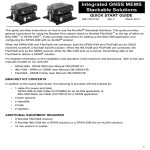
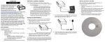
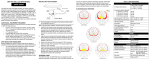
SPAN Technology for OEMV
QUICK START GUIDE
This guide provides the basic information
you need to set up and begin using your
SPAN Technology system.
BOX CONTENTS
In addition to this Quick Start Guide, the
following is provided in your SPAN package:
• 1 ProPak-V3 receiver and its Quick Start Guide
• 1 IMU (see the IMU Type column in Table 1 of this guide)
• 1 IMU to receiver interface cable
• 2 serial cables (1 straight through and 1 null modem)
• 1 I/O cable
• 1 DB9 to USB cable
• 2 12 V power cables (1 for receiver and 1 for IMU)
• 1 CD containing PC Utilities and product documentation
ADDITIONAL EQUIPMENT REQUIREMENTS
The following additional equipment is needed for a basic setup:
• A Windows-based PC with an RS-232 DB9 or USB port
• A power supply of +9 to +18 V DC (ProPak-V3)
• A separate power supply of +12 to +28 V DC for IMU
• A quality dual frequency GPS antenna such as the GPS702, or GPS-532 for airborne/high speed applications.
For L-Band corrections use the GPS-702L antenna.
• A TNC to appropriate antenna connector RF cable
2. Connect the IMU to the receiver using the IMU cable
provided. The cable plugs into the ProPak-V3 port labelled
AUX (for the iIMU, also plug its cable into the ProPak’s I/O
port) on the back of the receiver. See also the steps in the
Configuring the SPAN IMU section of this guide.
5. Select Serial, or USB, from the Type list and select the PC/
laptop port, that the DL-V3 is connected to, from the Port list.
3. Connect COM1 of the receiver to a computer/laptop COM
port using a null modem cable.
LN-200
or HG-1700
COMMUNICATE WITH THE SPAN SYSTEM
iIMU
Once the receiver is connected to the PC, antenna, and power
supply, install NovAtel’s PC Utilities CDU (Control and Display
Unit) and Convert. Installation instructions are in your receiver
Quick Start Guide. (Alternatively, use HyperTerminal to
communicate with the receiver. Refer to the OEMV Installation
and Operation User Manual.)
4. Connect the GPS antenna to the antenna port on the
receiver using an appropriate antenna cable.
5. Apply power to the IMU and then to the receiver. It is
recommended that you place a back-up battery between the
receiver and its voltage supply as a power buffer if installed
in a vehicle. When a vehicle engine is started, power can dip
to 9.6 V DC or cut-out to ancillary equipment causing the
receiver and/or IMU to lose lock and calibration settings.
6. Select 115200 from the Baud Rate list.
Start CDU on your PC to enable communication:
7. Uncheck the Use hardware handshaking checkbox.
1. Launch CDU from the Start menu folder specified during the
installation process. The default location is Start | Programs |
NovAtel OEMV | NovAtel CDU.
8. Select OK to save the new device settings.
2. Select Open.... from the Device menu.
9. Select the new configuration from the Available device
configs area of the Open dialog.
10. Select the Open button to open DL-V3 communications.
3. Select the New... button in the Open dialog box. The Options
| Configuration dialog opens.
As CDU establishes the communication session with the
receiver, it displays a progress box.
11. Select Tools | Logging Control Window from the CDU main
menu to control the receiver’s logging to files and serial
ports. Refer to CDU’s on-line Help for more information.
SET UP YOUR SPAN HARDWARE
Complete the following steps to set up and power your SPAN
system where the example graphics show the connections on
the back of the ProPak-V3 receiver.
1. Mount the IMU and antenna securely to a vehicle. Ensure
that the GNSS antenna and IMU cannot move relative to
each other. The distance and relative direction between
them must be fixed. See also Step 2 in the SPAN IMU
Configuration section of this guide.
the user device on the right to the ProPak-V3 I/O port.
Voltage
Supply
+
12. Use the Console window to enter commands. See also the
Post-Processing section of this guide.
-
You may also have a user point device such as video equipment.
Connect the device to the receiver’s I/O port using a cable that is
compatible with both the receiver and the device. Refer to your
device’s documentation for information on its connectors and
cables. The arrow along the cable in the figure indicates a MARKIN
pulse, refer to the OEMV Family Firmware Reference Manual, from
4. Use the
button at the top of the configurations selection
box to add a new configuration. To delete a configuration,
select it from the list and click on the
button. To duplicate
an existing configuration, click on the
button. You can
select any name in the list and edit it to change it.
To power down your receiver, ensure all windows, except Console,
are closed in CDU and then use the SAVECONFIG command.
CONFIGURE THE SPAN IMU
Configure SPAN Manually
Follow these steps to enable INS as part of the SPAN system
using software commands or see the next section, Configure
SPAN with CDU, to see the alternate method using CDU:
Follow these steps to enable INS as part of the SPAN system:
1. Issue the INTERFACEMODE and SETIMUTYPE commands
to specify the receiver COM port and IMU (Table 1). 1, 2
Table 1: Enable INS Commands
IMU Type
INTERFACEMODE
SETIMUTYPE
LN-200
com3 imu imu off
imu_ln200
iIMU-FSAS
com3 imarimu imarimu off
imu_imar_fsas
com3 imu imu off
imu_hg1700_ag11, or
imu_hg1700_ag17, or
imu_hg1700_ag58, or
imu_hg1700_ag62
HG1700
Basic configuration of the SPAN system is now complete.
The inertial filter starts once the GPS solution is solved and
the IMU is connected.
a)
A GPS antenna must be connected and tracking satellites
for operation.
b)
Enter the INTERFACEMODE command with COM3 as the
port value even if the ProPak-V3 port is labelled AUX.
2. Enter the distance from the IMU to the GNSS antenna using
the SETIMUTOANTOFFSET command. The offset between
the antenna phase centre and the IMU axes must remain
constant and be known accurately (m). The X (pitch), Y (roll)
and Z (azimuth) directions are clearly marked on the IMU
enclosure. The SETIMUTOANTOFFSET parameters are
(where the standard deviation fields are optional):
x_offset y_offset z_offset [x_stdev] [y_stdev] [z_stdev]
A typical RTK GPS solution is accurate to a few centimeters.
1. For the iIMU-FSAS, the receiver’s COM3 port must be in RS-422 mode
2. The iIMU-FSAS IMU requires that COM3, labelled as AUX on the
ProPak-V3, be in RS-422 mode. COM3 is factory-configurable for
RS-232 or RS-422 mode.
For the integrated INS/GPS system to have this level of
accuracy, the offset must be measured to within a millimeter.
Any bias between the two systems shows up directly in the
output position. For example, a 10 cm error in recording this
offset will result in at least a 10 cm error in the output.
If it is impossible to measure the IMU to GPS antenna offset
precisely, the offset can be estimated by carrying out the
Lever Arm Calibration Routine. Refer to the SPAN for OEMV
User Manual for details.
Configure SPAN Using CDU
Follow these steps to enable INS as part of the SPAN system
using the NovAtel CDU software utility:
1. Select Tools | SPAN Alignment Wizard from the CDU menu
to input your lever arm and vehicle to body rotation information. This wizard takes you through the steps to complete a
coarse or fast alignment, select the type of IMU and configure the receiver to IMU port to accept IMU data.
2. Select Tools | SPAN Calibration Wizard to calibrate your
lever arm or vehicle to body rotation information. This wizard
takes you through the steps to calibrate your lever arm and/
or vehicle to body rotation, as well as select the type of IMU
and configure the receiver port connected to the IMU and to
accept data
When you have completed making your selections in the
SPAN wizard, click on the OK button to enable your SPAN
system. Raw IMU data is now available and the INS filter
starts.
CONFIGURE GPS
Depending on the accuracy of the solution required, the GPS
can be augmented with a number of correction sources including
SBAS, L-Band and RTK (RTCA, RTCM, RTCM V3 and CMR).
Refer to the OEMV Installation and Operation Manual / ProPakV3 Quick Start, for SBAS, L-Band or RTK setup and operation.
LOG SPAN DATA
Raw GPS, IMU and navigation data (position, velocity, attitude)
are available from the system as ASCII or binary logs.
Data can be collected through CDU using the Logging Control
window, or sent out the receiver COM port to user-supplied data
collection software.
For post-processing applications, collect the data shown in the
Post-Processing section near the end of this guide.
For real-time applications, the GPS/INS solution is available
through the logs listed in the SPAN Technology for OEMV User
Manual including INSPOS, INSVEL, INSATT and INSPVA.
These logs can be collected at rates up to the IMU data rate;
however, there are some rate restrictions. Refer to the Data
Collection section in the SPAN Operation chapter of the SPAN
Technology for OEMV User Manual.
OPERATE THE SPAN SYSTEM
The system is ready to go once it is powered and the INS and
GPS are configured using the previously shown commands.
Observe the status of the system in CDU’s INS window or in the
status field of any of the INS solution logs (for example INSPOS,
INSVEL, INSATT and INSPVA).
INS data is available once there is a good GPS solution. Therefore,
an antenna must be connected for the system to function.
Allow the system to be stationary for at least 1 minute after the
GPS solution is computed for its initial system alignment. The
following status stages may be observed:
• The status changes from INS_INACTIVE to INS_ALIGNING
once the coarse alignment starts.
from the receiver due to limited satellite visibility or high
multipath conditions. The inertial filter may choose to
disregard this information and wait for the GPS quality to
improve. The solution is still valid during these times, it is
simply a warning flag that the GPS/INS solution is more
reliable than the GPS-only solution.
POST-PROCESS DATA
Post-processing requires collection of simultaneous data from
the base and rover stations. This includes accurate coordinates
of the base station and accurate measurement of the IMU to
antenna separation.
Collect the following data for post-processing:
• From the base station
• RANGECMPB ontime 1
• RAWEPHEMB onnew
•
From the rover station(s)
• RANGECMPB ontime 1
• RAWEPHEMB onnew
• RAWIMUSB onnew
SPAN system output is compatible with Inertial Explorer postprocessing software from the Waypoint Products Group, NovAtel
Inc. Visit our website at http://www.novatel.com for details.
QUESTIONS OR COMMENTS
If you have any questions or comments regarding your SPAN
system, please contact NovAtel Customer Service by:
Email:
Web:
Phone:
• The status changes to INS_ALIGNMENT_COMPLETE.
when the coarse alignment is complete. It normally stays in
this state until the system senses motion. Then when the
attitude solution converges to within specifications, the status changes to INS_SOLUTION_GOOD.
• The status may occasionally change to
INS_BAD_GPS_AGREEMENT. This status indicates that
the inertial solution has detected poor quality GPS positions
Fax:
[email protected]
www.novatel.com
1-800-NOVATEL (U.S. & Canada)
403-295-4900 (International)
403-295-4901
© Copyright 2006-2008 NovAtel Inc. All rights reserved.
Printed in Canada on recycled paper. Recyclable.
Unpublished rights reserved under international copyright laws.
GM-14915073
Rev 4
2008/05/25