1
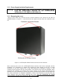
Operating Manual iCITE100-M-E / EX-2000-X2 iCITE100-S-E / EX-2000-X4 (English) This page is intentionally left blank. Document Number 406612 (See Last Page for Revision Details) For warranty information, refer to Terms and Conditions at http://www.extronics.com ©2014 Extronics Limited. This document is Copyright Extronics limited. Extronics reserve the right to change this manual and its contents without notice, the latest version applies. 2 Contents 1 2 3 4 5 6 7 8 9 Introduction .................................................................................................. 4 Safety Information and Notes .......................................................................... 5 2.1 Storage of this Manual .............................................................................. 5 2.2 Special Conditions for Safe Use .................................................................. 5 2.2.1 Class 1 Division 2 ............................................................................... 5 2.3 List of Notes ............................................................................................ 5 2.4 Class 1 Division 2 Approvals Information ..................................................... 7 Installation and Setting to Work....................................................................... 8 3.1 Installation .............................................................................................. 8 3.1.1 Power Supply and Interconnection Requirements .................................... 8 3.1.2 Power Supply Isolation Requirements .................................................... 9 3.1.3 Removing the cover ............................................................................ 9 3.1.4 Mounting Information ....................................................................... 10 3.1.5 Cable Termination Requirements ........................................................ 12 3.2 Connections to Master Unit ...................................................................... 13 3.2.1 Ethernet Connection ......................................................................... 14 3.2.2 Power Connection............................................................................. 14 3.2.3 Chain Connection ............................................................................. 14 3.2.4 Earthing.......................................................................................... 14 3.2.5 Master Unit Terminal Allocations ......................................................... 15 3.3 Connections to Slave Unit ........................................................................ 16 3.3.1 Chain In Connection ......................................................................... 16 3.3.2 Chain Out Connection ....................................................................... 17 3.3.3 Termination Jumper Setup................................................................. 17 3.3.4 Earthing.......................................................................................... 17 3.3.5 Slave Unit Terminal Allocations .......................................................... 18 Intended Purpose Usage ............................................................................... 19 4.1 Transportation and Storage ..................................................................... 19 4.2 Authorized Persons ................................................................................. 19 4.3 Cleaning and Maintenance ....................................................................... 19 4.4 Safety Precautions.................................................................................. 20 4.5 Cleaning and Maintenance Intervals .......................................................... 20 4.6 Aggressive substances and environments .................................................. 20 4.7 Exposure to external stresses .................................................................. 20 Technical Data ............................................................................................ 21 Marking ...................................................................................................... 22 Type Codes ................................................................................................. 23 Manufacturer .............................................................................................. 23 Manual Revision .......................................................................................... 23 Figure Figure Figure Figure Figure Figure Figure Table Table Table Table Table 1: 2: 3: 4: 5: 6: 7: 1: 2: 3: 4: 5: iCITE100/EX-2000 Power/Interconnection Options ....................................... 8 iCITE100/EX-2000 Enclosure access screw locations .................................... 9 View of iCITE100/EX-2000 with Enclosure Lid Removed.............................. 10 Enclosure wall-mounting holes ................................................................ 11 Pole Mounting ...................................................................................... 11 Master Unit Connector Locations ............................................................. 13 Slave Unit Connector Locations ............................................................... 16 Cable to Gland Descriptions ..................................................................... 10 Cable Termination Requirements .............................................................. 12 Master Unit Terminal Allocations .............................................................. 15 Termination Jumper Setup ...................................................................... 17 Slave Unit Terminal Allocations ................................................................ 18 3 1 Introduction The Extronics iCITE100-M-E / iCITE100-S-E / EX-2000-X2 / EX-2000-X4 are MET Canada Class I Division 2 approved versions of the Aeroscout EX-2000 unit; this is a hardware component of Aeroscout's industry-leading visibility system for active RFID and location applications. The device adds value by extending the system to provide robust and sophisticated RFID detection and identification capabilities, using the same Wi-Fi-based active RFID tags that can also be accurately located in real time by the Aeroscout system. The iCITE100/EX-2000 uses a 125KHz ASK modulated field to trigger Extronics iTAG100/TAG-2000 devices as they come within range of the iCITE100/EX-2000 field. This causes the tags to transmit a 2.4GHz WiFi message that is received by a Location Receiver or compatible access point. This provides instant knowledge that a tagged asset or person passed through a gate, doorway or some other tightly defined area. There are two variants of the iCITE100/EX-2000; master and slave. The master unit may be operated in stand-alone mode, supplied either by IEEE802.3af compliant power-overEthernet (POE) or from a 24VAC/DC supply. The master unit communicates with the Aeroscout software via 10/100BASET Ethernet. The slave unit must be connected to a master unit, as it is powered from the master and also receives synchronisation data via RS485. Up to three slave units may ‘chained’ in series from one master unit. The slave units are used to extend the range of a master unit, for example to reach both sides of a large doorway. 4 2 Safety Information and Notes 2.1 Storage of this Manual Keep this user manual safe and in the vicinity of the device. All persons who have to work on or with the device should be advised on where the manual is stored. 2.2 Special Conditions for Safe Use 2.2.1 Class 1 Division 2 None specified. 2.3 List of Notes The notes supplied in this chapter provide information on the following. Danger! / Warning! o Possible hazard to life or health. Caution o Possible damage to property. Important o Possible damage to enclosure, device or associated equipment. Information o Notes on the optimum use of the device o Warning! Installation and maintenance of the iCITE100-M-E/ iCITE100-S-E / EX-2000-X2 / EX-2000-X4 must only be carried out by suitably qualified personnel. The equipment must be installed in accordance with CEC requirements. Warning! All cables connected to the iCITE100/EX-2000 are to be installed using cable glands suitable for the hazardous area in which the unit is being installed, fitted by a competent person. Warning! Any cable glands which are not in use MUST be replaced by blanking plugs suitable for the hazardous area in which the unit is being installed, fitted by a competent person. Warning! Do not open the enclosure while the equipment is powered, unless the area is known to be free of ignitable concentrations of flammable substances. Warning! The iCITE100/EX-2000 units do not require an earth connection for electrical safety purposes. However, any un-used cable cores must be terminated or earthed, and all cable shields/screens must be earthed. Earth terminals are provided within the iCITE100/EX-2000 units for this purpose. Warning! Ensure that any cables connected to the iCITE100/EX-2000 have adequate mechanical protection to avoid damage to the wires. Failure to do so could cause shorts or exposure of non-insulated wires to potentially explosive environments. 5 Warning! Ensure that the lid is secure, the lid gasket is un-damaged, correct cable glands are fitted and the unit is correctly wired before applying power to the iCITE100/EX-2000. Warning! Do not connect more than one source of power to the iCITE100/EX2000 units. Warning! The maximum power supply voltage for the master unit external power supply inputs is 24V AC/DC. Warning! Never connect a slave unit to power supply of more than 24V. Warning! A suitably-rated and readily-accessible disconnect device shall be incorporated external to the iCITE100-M-E/ iCITE100-S-E /EX2000-X2/EX-2000-X4. Important iCITE100/EX-2000 master units may only be powered either from IEEE 802.3af POE via the Ethernet interface, or from 24V AC/DC via the power input terminals - see Section 3.1.1. Important iCITE100/EX-2000 slave units may be powered either from the ‘chained’ power supply connection from a master unit, or from 24V AC/DC via the power input terminals. The slave unit is NOT IEEE 802.3af POE compatible - see Section 3.1.1. Important The master and slave iCITE100/EX-2000 units have different terminal connections. Follow the correct pin connections for the unit being installed. Important A maximum of 3 slave iCITE100/EX-2000 units may be powered from a master unit - see Section 3.1.1. Important The iCITE100/EX-2000 units contain fuses which limit the current into each unit to 800mA when powered from an external power supply, or 400mA when powered from POE. These fuses however do not limit the current available to be supplied to the next device when units are connected in a chain - see Section 3.1.1. The fuses are not user-accessible. 6 2.4 Class 1 Division 2 Approvals Information The iCITE100-M-E, iCITE100-S-E, EX-2000-X2 and EX-2000-X4 carry the following approval: Class I, Division 2, Groups A, B, C, D Hazardous Location Classe I, Division 2, Groupes A, B, C, D Emplacement Dangereux TEMPERATURE CODE/CODE DE LA TEMPÉRATURE T4 -30oC ≤ Tamb ≤ +60oC The products are approved to the following standards: CSA C22.2 No. 60950-1-07 (R2012) - Safety of Information Technology Equipment. CSA 22.2 No. 213-M1987 (R2013) - Intrinsically Safe and Non-Incendive Equipment for Use in Hazardous Locations 7 3 Installation and Setting to Work 3.1 Installation The iCITE100/EX-2000 is simple to install and can be secured directly to a suitable surface using the mounting holes in the enclosure. 3.1.1 Power Supply and Interconnection Requirements The iCITE100/EX-2000 master and slave variants may be powered in a number of different ways. The diagram below is not exhaustive; various combinations of the configurations shown can be used, provided the rules shown are not contravened. Single Master iCITE100/EX2000. Do NOT connect both power sources Encapsulated Exciter electronics 400mA Fuse Not user accessible Encapsulated Exciter electronics 800mA Fuse Not user accessible OR Ethernet input terminals 1-8 External power input terminals IEEE802.3af Power Over -Ethernet 12.95W Max 24V AC/DC Max. 800mA Chained Master-Slave iCITE100/EX2000 units: maximum 3 slave units permitted Master unit Slave unit 1 Slave unit 2 Slave unit 3 Encapsulated Exciter electronics Encapsulated Exciter electronics Encapsulated Exciter electronics Encapsulated Exciter electronics 800mA Fuse Not user accessible External power input terminals 800mA Fuse Not user accessible Chain Out terminals 24V AC/DC Max. 3.2A Chain In terminals 800mA Fuse Not user accessible Chain Out terminals 24 AC/DC Max. 2.4A + RS485 Chain In terminals 800mA Fuse Not user accessible Chain Out terminals 24V AC/DC Max. 1.6A + RS485 Chain In terminals Chain Out terminals 24V AC/DC Max. 800mA + RS485 Individually Powered Master-Slave iCITE100/EX2000 units with synchronisation: maximum 7 slave units permitted Master unit Slave unit 1 Slave unit 2 Slave unit 7 Encapsulated Exciter electronics Encapsulated Exciter electronics Encapsulated Exciter electronics Encapsulated Exciter electronics 800mA Fuse Not user accessible External power input terminals 24V AC/DC Max. 800mA Chain Out terminals 1,2,3,6 800mA Fuse Not user accessible Chain In terminals 1,2,3,6 Chain In terminals 4+5, 7+8 800mA Fuse Not user accessible Chain Out terminals 1,2,3,6 RS485 only Chain In terminals 1,2,3,6 Chain In terminals 4+5, 7+8 Chain Out terminals 1,2,3,6 ... 800mA Fuse Not user accessible Chain In terminals 1,2,3,6 Chain In terminals 4+5, 7+8 Chain Out terminals 1,2,3,6 RS485 only 24V AC/DC Max. 800mA 24V AC/DC Max. 800mA Figure 1: iCITE100/EX-2000 Power/Interconnection Options 8 24V AC/DC Max. 800mA 3.1.2 Power Supply Isolation Requirements Warning! A suitably-rated and readily-accessible disconnect device shall be incorporated external to the iCITE100-M-E/ iCITE100-S-E /EX-2000-X2/EX-2000-X4. 3.1.3 Removing the cover Using a 5mm Allen key unscrew all four screws located in the corners of the box as indicated below in Figure 2 - note that these are captive screws that are retained in the lid. Figure 2: iCITE100/EX-2000 Enclosure access screw locations After removing the cover the iCITE100/EX-2000 antenna and screw terminals will be exposed. It is necessary to remove the antenna to gain access to the Ex e screw terminals. To do this, remove the 4 nuts and washers as indicated in Figure 3, and carefully lift the antenna off the screw pillars. The antenna will come pre-installed, when removing the antenna, be careful not to put a strain on the wires connected to the antenna. It is not necessary to remove the wires connecting the antenna to the PCB from the screw terminals to complete installation. Ensure the antenna is secured with the same washers and nuts before replacing the cover. Do not substitute for metal nuts/washers as this may affect the RF performance. 9 Figure 3: View of iCITE100/EX-2000 with Enclosure Lid Removed Table 1 below describes which wire each cable gland should be used for. If one of the cables is not required due to the configuration required the cable gland(s) not in use must be replaced with a suitably certified blanking plug. Gland 1 2 3 Master Purpose Ethernet External Power In CHAIN Out Slave Purpose Not used, stopping plug fitted CHAIN Out CHAIN In Table 1: Cable to Gland Descriptions 3.1.4 Mounting Information If the enclosure is to be mounted directly to a wall / mounting plate, please see below for mounting hole locations and sizes (all dimensions in mm). You should mount the enclosure to the wall with the lid removed to allow access to the mounting holes, then refit the enclosure lid and securely tighten the screws making sure not to over-tighten them. 10 Figure 4: Enclosure wall-mounting holes If mounting the enclosure to a pipe using the Extronics pipe mounting bracket (Extronics Part number A070031), please see below for mounting details. The enclosure should be supplied with the pipe mount bracket fitted. The bracket is designed for mounting to a 2” diameter pipe, as shown in Figure 5. Tighten nuts to secure to pole Figure 5: Pole Mounting 11 Alternatively, pipe mount bracket iWAPMB04 may be used to mount the enclosure to a 2” diameter pipe as shown below: 3.1.5 Cable Termination Requirements The iCITE100/EX-2000 units are equipped with safety-approved screw terminals for all connections. These terminals are designed to accept the following wire gauges. Connections must comply with the requirements of this table. Connection Type Single solid wire Single stranded wire Stranded wire with ferrule, no plastic sleeve Stranded wire with ferrule, with plastic sleeve 2 solid conductors, same cross section 2 stranded conductors, same cross section 2 stranded conductors, same cross section, with ferrule, no plastic sleeve Min. Conductor CrossSection/mm2 0.2 0.2 0.25 0.25 0.2 0.25 Max. Conductor CrossSection/mm2 2.5 2.5 1.5 1.5 0.75 0.75 0.25 0.34 Table 2: Cable Termination Requirements 12 Important The master and slave iCITE100/EX-2000 units have different terminal connections. Follow the correct pin connections for the unit being installed. 3.2 Connections to Master Unit Important The Master Exciter cannot be configured using exciter manager Important IP Reset Switch - The iCITE100 / EX-2000 units have no option for IP reset due to the hazardous area protection of the exciter Figure 6: Master Unit Connector Locations Depending on the configuration required there may be stopping plugs instead of cable glands in the enclosure. For example if the unit is to be used as a single iCITE100/EX2000 with no Ethernet connection, only a power supply will be needed. Therefore only the middle cable gland will be needed and the other 2 glands will be replaced with stopping plugs. 13 3.2.1 Ethernet Connection To connect a Cat-5 cable to the Ethernet screw terminals, feed the cable through the leftmost cable gland and strip the wire to expose the 8 individual wire cores as describes above in table 4.2 and also the outer sheath. Terminate the wires and outer sheath in bootlace ferrules. Any earth wire should be sleeved. Place the correct wires into the corresponding screw terminal, i.e. Cat-5 wire 1 into Ethernet – 1 and Cat-5 wire 8 into Ethernet – 8. Place the terminated outer sheath into the earth terminal C1-21. Ensure the wires are securely screwed into place. 3.2.2 Power Connection If the iCITE100/EX-2000 is to be powered via an external power source, ensure the power supply is 24V ac/dc only. Feed the cable through the middle cable gland and strip the wire to expose the two power lines and the outer sheath, then strip and terminate the exposed wires with bootlace ferrules. Any earth wire should be sleeved. Place the wires into the corresponding screw terminal as indicated in below in table 4.3. The earth wire should be placed into screw terminal C1 – 10. Ensure the wires are securely screwed in place. 3.2.3 Chain Connection If the iCITE100/EX-2000s are to be used in chained mode, the Chain Out on the master unit (connector 1) will be used to connect the first slave unit. The Chain connection should also be made using a Cat-5 cable. Feed the cable through the right hand cable gland, then strip and terminate the wires with bootlace ferrules. Any earth wire should be sleeved. Place the outer sheath into the earth terminal C1-1 and the corresponding cat-5 wires into the Chain Out screw terminals as described below in Table 3, i.e. Cat-5 wire 1 into Chain Out – 1. Ensure the wires are securely screwed in place. 3.2.4 Earthing Warning! The iCITE100/EX-2000 units do not require an earth connection for electrical safety purposes. However, any unused cable cores must be terminated or earthed, and all cable shields/screens must be earthed. Earth terminals are provided within the iCITE100/EX-2000 units for this purpose. 14 3.2.5 Master Unit Terminal Allocations Master Connector/Pin No. C1 C1 C1 C1 C1 C1 C1 C1 C1 C1 C1 C1 C1 C1 C1 C1 C1 C1 C1 C1 C1 C2 C2 C2 C2 C3 C3 - 1 2 3 4 5 6 7 8 9 10 11 12 13 14 15 16 17 18 19 20 21 1 2 3 4 1 2 Pin Description Earth (Ethernet outer sheath) Ethernet – 1 Ethernet – 2 Ethernet – 3 Ethernet – 4 Ethernet – 5 Ethernet – 6 Ethernet – 7 Ethernet – 8 External Power + External Power Earth (Power cable outer sheath) RS485 Out – 1 RS485 Out – 2 RS485 Out – 3 RS485 Out – 4 RS485 Out – 5 RS485 Out – 6 RS485 Out – 7 RS485 Out – 8 Earth (Chain Out) Long Range Antenna + (Blue) Long Range Antenna – (Green) Short Range Antenna + (Red) Short Range Antenna – (Black) Earth Earth Table 3: Master Unit Terminal Allocations 15 3.3 Connections to Slave Unit Important IP Reset Switch - The iCITE100 / EX-2000 units have no option for IP reset due to the hazardous area protection of the exciter The slave iCITE100/EX-2000’s are powered and controlled via a master unit. RS485 data and power is fed into a slave unit from a master unit. It is possible to have up to 7 slave units attached to a master unit in a chain (see Figure 1). The first slave will accept an RS485 input from the master, this unit will then send an RS485 output to the input of the subsequent slave units. Figure 7: Slave Unit Connector Locations 3.3.1 Chain In Connection The Chain In terminals on connector 1 will be used to connect the unit to either a master or another slave unit’s Chain Out terminals. The Chain In connection should be made using a Cat-5 cable. Feed the cable through the left hand cable gland, then strip and terminate the wires with bootlace ferrules. Any earth wire should be sleeved. Place the outer sheath into the earth terminal C1-1 and the corresponding cat-5 wires into the Chain in screw terminal as described below in Table 5, i.e. Cat-5 wire 1 into Chain In – 1. Ensure the wires are securely screwed in place. 16 3.3.2 Chain Out Connection If another slave is to be connected to the Chain Out pins on connector 1 will be used to connect the second slave unit. The Chain Out connection should also be made using a cat-5 cable. Feed the cable through the right hand cable gland, then strip and terminate the wires with bootlace ferrules. Any earth wire should be sleeved. Place the outer sheath into the earth terminal C1-18 and the corresponding Cat-5 wires into the Chain Out screw terminal as described below in Table 5, i.e. Cat-5 wire 1 into Chain Out – 1. Ensure the wires are securely screwed in place. 3.3.3 Termination Jumper Setup The last slave in a chain needs to have its RS485 connections to be terminated for correct operation; this is done by adding short jumper links to the screw terminals. These links must be made with insulated wire of a suitable gauge, fitted with bootlace ferrules as described in Table 2. Refer to Table 4 for termination settings. Note that the master unit does not require any configuration for chaining use, it is preterminated internally. Configuration Master - Slave 1 Master Slave 1 - Slave 2 Master - Slave 1 Slave 2 - Slave 3 Termination Required? Slave 1 = Yes Slave 1=No Slave 2 = Yes Slave 1=No Slave 2 = Yes Slave 3 = Yes Term 1 & Term 2 Configuration Slave 1 = Linked Slave 1 = Not Linked Slave 2 = Linked Slave 1 = Not Linked Slave 2 = Not Linked Slave 3 = Linked Term 3 configuration Slave 1 = A+B Slave 1 = B+C Slave 2 = A+B Slave 1 = B+C Slave 2 = B+C Slave 3 = A+B Table 4: Termination Jumper Setup The terminals on the slave unit used for these links are as follows: Term Term Term Term 1 2 3 3 linked = wire link C1-1 and C1-2 linked = wire link C1-3 and C1-4 A+B = wire link C1-5 and C1-6 B+C = wire link C1-6 and C1-7 3.3.4 Earthing Warning! The iCITE100/EX-2000 units do not require an earth connection for electrical safety purposes. However, any unused cable cores must be terminated or earthed, and all cable shields/screens must be earthed. Earth terminals are provided within the iCITE100/EX-2000 units for this purpose. 17 3.3.5 Slave Unit Terminal Allocations Slave Connector/Pin No. C1 C1 C1 C1 C1 C1 C1 C1 C1 C1 C1 C1 C1 C1 C1 C1 C1 C1 C1 C1 C1 C1 C1 C1 C1 C2 C2 C2 C2 C3 C3 - 1 2 3 4 5 6 7 8 9 10 11 12 13 14 15 16 17 18 19 20 21 22 23 24 25 1 2 3 4 1 2 Pin Name Term1A Term1B Term2A Term2B Term3A Term3B Term3C Earth Chain Output – 8 Chain Output – 7 Chain Output – 6 Chain Output – 5 Chain Output – 4 Chain Output – 3 Chain Output – 2 Chain Output – 1 RS485 Input – 8 RS485 Input – 7 RS485 Input – 6 RS485 Input – 5 RS485 Input – 4 RS485 Input – 3 RS485 Input – 2 RS485 Input – 1 Earth Short Range Antenna + (Red) Short Range Antenna – (Black) Long Range Antenna + (Blue) Long Range Antenna – (Green) Earth Earth Table 5: Slave Unit Terminal Allocations 18 4 Intended Purpose Usage Important Before setting the units documentation carefully. to work, read the technical Important The latest version of the technical documentation or the corresponding technical supplements is valid in each case. The iCITE100/EX-2000 is built using modern components and is extremely reliable in operation; however it must only be used for its intended purpose. Please note that the intended purpose also includes compliance with the instructions issued by the manufacturer for installation, setting up and service. Any other use is regarded as conflicting with the intended purpose. The manufacturer is not liable for any subsequent damage resulting from such inadmissible use. The user bears the sole risk in such cases. 4.1 Transportation and Storage All iCITE100/EX-2000 devices must be so transported and stored that they are not subjected to any excessive mechanical stresses. 4.2 Authorized Persons Only persons trained for the purpose are authorized to handle the iCITE100/EX-2000; they must be familiar with the unit and must be aware of the regulation and provisions required for explosion protection as well as the relevant accident prevention regulations. 4.3 Cleaning and Maintenance The iCITE100/EX-2000 and all its components require no maintenance. All work on the iCITE100/EX-2000 by personnel who are not expressly qualified for such activities will cause the safety approval and the guarantee to become void. 19 4.4 Safety Precautions Important For the installation, maintenance and cleaning of the units, it is absolutely necessary to observe the applicable regulations and provisions concerned with explosion protection. 4.5 Cleaning and Maintenance Intervals The cleaning intervals depend on the environment where the system is installed. 4.6 Aggressive substances and environments The iCITE100/EX-2000 is not designed to come into contact with aggressive substances or environments, please be aware that additional protection may be required. 4.7 Exposure to external stresses The iCITE100/EX-2000 is not designed to be subjected to excessive stresses e.g. vibration, heat, impact. Additional protection is required to protect against these external stresses. The iCITE100/EX-2000 will require additional protection if it is installed in a location where it may be subjected to damage. 20 5 Technical Data Range Adjustable from 50 centimetres to 6.5 metres (20 inches to 21 feet) Tag Type Extronics iTAG100 tags Aeroscout TAG-2000-X tags Dimensions 255 x 250 x 120 mm (w x h x d) 10 x 9.85 x 4.72 inches Weight Approx 2.5 Kg (5.5 lbs) Ambient Temperature -30ºC to +60ºC (-22ºF to +140ºF) Relative humidity 0 to 95%, non-condensing Housing Black antistatic GRP enclosure Ingress Protection IP66 / NEMA4 Electrical Connection Screw terminals Cable Entry 3 x M20 entries for suitably certified plastic cable glands Mounting Wall / ceiling, or pole mounting with optional accessory Management Settings configured remotely using Aeroscout System Manager Software LF Channel 125KHz ASK modulation Field Intensity Limits (ETSI) 37.3 dBµA/m at 10m Propagation Limits (FCC) 21.8 dBµV/m at 10m Radio Certification FCC Part 15, sub part C class B, sub part B, EN300-330, EN301489, RSS 210 (Canada) Safety Certification MET Canada Class I Division 2 T4 Listing Number E113811 21 6 Marking 22 7 Type Codes Type Code iCITE100-M-E iCITE100-S-E EX-2000-X2 EX-2000-X4 Description Extronics-Branded Master Exciter MET Canada Class I Division 2 T4 Approved Extronics-Branded Slave Exciter MET Canada Class I Division 2 T4 Approved Aeroscout-Branded Master Exciter MET Canada Class I Division 2 T4 Approved Aeroscout-Branded Slave Exciter MET Canada Class I Division 2 T4 Approved -30oC to +60oC -30oC to +60oC -30oC to +60oC -30oC to +60oC 8 Manufacturer The iCITE100/EX-2000 is manufactured by: Extronics Ltd, 1 Dalton Way, Midpoint 18, Middlewich Cheshire CW10 0HU UK Tel. +44(0)845 2775000 Fax. +44(0)845 2774000 E-mail: [email protected] We: www.extronics.com 9 Manual Revision Revision 1.0 2.0 2.1 Description Initial Release Slave antenna terminal swap Added Master / Slave config info 23 Date 08/08/2014 11/09/2014 16/01/2015 By BTS BTS AJP