1
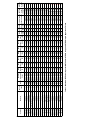
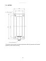
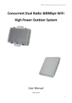
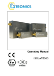
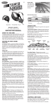
Operating Manual
iANT2xx Series of Antennas
Operating Manual
This page is intentionally left blank.
Document Number 403449 (See Last Page for Revision Details)
©2014 Extronics Limited. This document is Copyright Extronics limited.
Extronics reserve the right to change this manual and its contents without notice, the latest
version applies.
2
Operating Manual
Contents
1
2
Introduction.......................................................................................................... 4
Safety Information and Notes .............................................................................. 5
2.1 Storage of this Manual................................................................................... 5
2.2 List of Notes .................................................................................................. 5
2.3 Intended Purpose Usage ............................................................................... 8
2.4 Transportation and Storage ........................................................................... 8
2.5 Authorized Persons ....................................................................................... 8
2.6 Cleaning and Maintenance ............................................................................ 8
2.7 Safety Precautions ........................................................................................ 9
2.8 Cleaning and Maintenance Intervals ............................................................. 9
2.9 Aggressive substances and environments .................................................... 9
2.10
Exposure to external stresses .................................................................... 9
3 Mounting Details ................................................................................................ 10
3.1 iANT200 ...................................................................................................... 10
3.2 iANT212 ...................................................................................................... 10
3.3 iANT213 ...................................................................................................... 10
3.4 iANT214 ...................................................................................................... 11
3.5 iANT215 ...................................................................................................... 12
3.6 iANT216 ...................................................................................................... 12
3.7 iANT217 ...................................................................................................... 13
3.8 iANT218 / iANT219 / iANT220 / iANT221 .................................................... 14
3.9 iANT222 ...................................................................................................... 15
4 Technical Data .................................................................................................. 16
4.1 iANT200 ...................................................................................................... 16
4.2 iANT212 ...................................................................................................... 17
4.3 iANT213 ...................................................................................................... 18
4.4 iANT214 ...................................................................................................... 19
4.5 iANT215 ...................................................................................................... 19
4.6 iANT216 ...................................................................................................... 20
4.7 iANT217 ...................................................................................................... 21
4.8 iANT218 ...................................................................................................... 22
4.9 iANT219 ...................................................................................................... 23
4.10 iANT220 ...................................................................................................... 24
4.11
iANT221 ................................................................................................... 25
4.12
iANT222 ................................................................................................... 26
5 Manual Revision ................................................................................................ 27
3
Operating Manual
1 Introduction
The iANT2xx range of rugged antennas provides a comprehensive selection of
antennas that can operate in the UHF, GSM, 2.4GHz or 5.8GHz WiFi frequency
bands, all of which are suitable for outdoor use at they have an IP rating of IP66 or
higher, and are protected against UV damage and corrosion in offshore
environments.
Please Note: The iANT2xx range of antennas is classed as “Simple Apparatus”
under international intrinsic safety standards. IEC 60079-25 requires that simple
apparatus equipment used in an intrinsically safe electrical system is compliant with
IEC 60079-0, IEC 60079-11, IEC 60079-14 & IEC 60079-25. Extronics has assessed
the iANT2xx antenna range together with our intrinsically safe certified wireless
products to provide solutions compliant to all relevant standards. Therefore iANT2xx
antennas can be deployed in a hazardous area, as part of an Extronics system,
without the need to undergo further assessment. Compliance is also maintained if an
iANT2xx antenna is used with the Extronics iSOLATE500 RF galvanic isolator. If the
antenna is not to be used with Extronics’ products, then the system designer must
assess the hazard and demonstrate compliance to the relevant standards.
4
Operating Manual
2 Safety Information and Notes
2.1 Storage of this Manual
Keep this user manual safe and in the vicinity of the device. All persons who have to work on
or with the device should be advised on where the manual is stored.
2.2 List of Notes
The notes supplied in this chapter provide information on the following.
• Danger / Warning.
o Possible hazard to life or health.
• Caution
o Possible damage to property.
• Important
o Possible damage to enclosure, device or associated equipment.
• Information
o
Notes on the optimum use of the device
Warning
The iANT2xx series are classified as simple apparatus. The application
in which any antennas are to be used, must be assessed for Uo, Io,
maximum permissible capacitance and inductance, and PCB width
trace/wire gauge in accordance with IEC 60079-11. Do not use an
iANT2xx antenna without first contacting Extronics for guidance and
recommendations for the use of the iANT2xxs with specific hardware.
Important
Installation of this equipment shall be carried out by suitably trained
personnel in accordance with the applicable code of practice (IEC 6007914).
Important
The antennas and associated wiring should be periodically inspected for
damage, in accordance with the applicable code of practice (IEC 6007917)
Warning
Antennas which are not marked suitable for Group I in Table 1 must NOT
be used in Group I or Zone 0.
Warning
Aluminium mounting brackets cannot be used in Group I or Zone 0
hazardous areas.
Warning
The iANT2xx antennas are an electrostatic charging hazard; clean only
with a damp cloth. The iANT2xx antennas should have a label stating
that they are an electrostatic hazard.
5
Operating Manual
Warning
Do not exceed the Effective Isotropic Radiated Power (EIRP) for the gas
group in which the iANT2xx will be operating. The RF output of the
transceiver will vary depending on the hardware and antenna used. The
maximum hardware limit of the access point must be used to calculate
the EIRP – software control by the user of the RF power is not allowed
- Group IIC – 2W (+33dBm)
- Group IIB – 3.5W (+35.4dBm)
- Group IIA/I/III – 6W (+37.7dBm)
Refer to Table 1 for specific antenna details.
Important
Important
Important
iANT2xx are only certified for use in ambient temperatures in the ranges
specified in Table 1 and should not be used outside this range.
Do not exceed the Effective Isotropic Radiated Power (EIRP) limit for the
country / region of operation
Repair of the iANT2xx shall only be carried out by the manufacturer. The
antenna contains no user-serviceable parts.
6
2.4GHz
5.8GHz
iANT200-24
2.4&5.8GHz
860-960MHz
2.4&5.8GHz
2.4GHz
iANT216
iANT218
7.5
7
2.4GHz
iANT222
iANT221
o
o
Sector -40oC to 70oC
Sector -30oC to 60oC
Sector -40 C to 65 C
Sector -55oC to 65oC
o
Sector -40oC to 70oC
Sector -55oC to 65oC
Sector -20oC to 70oC
Sector -20oC to 70oC
Omni -40oC to 80oC
Omni -40oC to 70oC
Sector -40 C to 80 C
Sector -40oC to 80oC
Sector -40oC to 80oC
o
Omni -30oC to 80oC
Omni -30oC to 80oC
Omni -40oC to 85oC
Omni -40oC to 85oC
Omni -40oC to 80oC
Omni -40oC to 70oC
Operating
Temperature
Range
0.4
0.36
0.03
0.06
0.05
0.11
0.63
0.32
0.4
0.32
0.08
0.28
0.32
0.63
1.12
0.63
0.5
0.32
0.63
26.0
25.6
14.8
17.8
17.0
20.4
28.0
25.1
26.0
25.1
19.0
24.5
25.1
28
30.5
28
27
30.5
30.5
0.7
0.62
0.04
0.11
0.09
0.2
1.11
0.55
0.7
0.55
0.14
0.49
0.55
1.11
1.97
1.11
0.88
0.55
1.11
28.5
27.9
16.0
20.4
19.5
23.0
30.5
27.4
28.5
27.4
21.5
26.9
27.4
30.5
32.9
30.5
29.4
27.4
30.5
1.2
1.07
0.08
0.19
0.15
0.34
1.9
0.95
0.68
0.95
0.24
0.85
0.95
1.9
3.37
1.9
1.51
0.95
1.9
30.8
30.3
19.0
22.8
21.8
25.3
32.8
29.8
1.2
29.8
23.8
29.3
29.8
32.8
35.3
32.8
31.8
29.8
32.8
1.2
N/A
N/A
N/A
N/A
N/A
N/A
0.95
0.68
0.95
0.24
0.85
0.95
1.9
3.37
1.9
1.51
0.95
1.9
30.8
N/A
N/A
N/A
N/A
N/A
N/A
29.8
1.2
29.8
23.8
29.3
29.8
32.8
35.3
32.8
31.8
29.8
32.8
0.39
0.39
0.08
0.19
0.15
0.34
0.39
0.39
0.39
0.39
0.24
0.39
0.39
0.39
0.39
0.39
0.39
0.39
0.39
Max Max
Max
Max
Max
Max
Max
Max
Max
Power Power
Power IIC Power IIC Power IIB Power IIB Power IIA Power IIA Power
Grp I Grp III
(W)
(dBm)
(W)
(dBm)
(W)
(dBm) Grp I (W)
(dBm) (W)
25.9
25.9
19.0
22.8
21.8
25.3
25.9
25.9
25.9
25.9
23.8
25.9
25.9
25.9
25.9
25.9
25.9
25.9
25.9
T6 @ 60 C
o
o
T5 @ 70 C
T6 @ 65 C
o
T6 @ 65 C
o
T6 @ 65 C
o
o
T6 @ 65 C
T4 @ 70 C
o
o
T6 @ 70 C
T6 @ 70 C
o
o
T6 @ 80 C
T6 @ 80 C
o
T6 @ 80 C
o
T6 @ 80 C
o
T6 @ 70 C
o
T5 @ 85 C
o
T6 @ 80 C
o
T5 @ 85 C
o
T6 @ 80 C
o
o
T6 @ 80 C
T135 @ 60 C
o
o
T135 @ 70 C
o
T135 @ 65 C
T135 @ 65 C
o
o
T135 @ 65 C
o
T135 @ 65 C
T135 @ 70 C
o
o
T135 @ 70 C
T135 @ 70 C
o
o
T135 @ 80 C
o
T135 @ 80 C
o
T135 @ 80 C
T135 @ 80 C
o
o
T135 @ 70 C
o
T135 @ 85 C
o
T135 @ 80 C
T135 @ 85 C
o
o
T135 @ 80 C
o
T135 @ 80 C
Y
N
N
N
N
N
N
Y
Y
Y
Y
Y
Y
Y
Y
Y
Y
Y
Y
Max
T Class at
Suitable
Power T Class at Max RF
Max RF
for Group
Grp III Power (Group II)
Power
I or Zone
(dBm)
(Group III)
0 Use?
Table 1: Maximum RF Power Input for iANT200 for ATEX Groups, and ATEX Simple Apparatus T-Class
19
15
5.8GHz
2.4&5.8GHz
iANT220-5000
iANT220-2400
16
5.8GHz
2.4GHz
12
5
8
7
8
iANT219-5000
iANT219-2400
iANT217
iANT215
14
8.5
8
2.4GHz
2.4GHz
5.8GHz
2.4-5.8GHz
iANT214-2400
iANT214-2400D
iANT214-5000
5
5.8GHz
2.5
5
6
8
5
iANT213-5000
iANT212
2.4-5.8GHz
iANT213-QB 806-960MHz/1710-2170MHz
iANT213-2400
2.4GHz
iANT200-58
Frequency
Antenna
Max. Gain
Pattern
(dBi)
2.3 Intended Purpose Usage
Important
Before setting the units to work, read the technical documentation
carefully.
Important
The latest version of the technical documentation or the corresponding
technical supplements is valid in each case.
The iANT2xx series is built using modern components and is extremely reliable in
operation; however it must only be used for its intended purpose. Please note that
the intended purpose also includes compliance with the instructions issued by the
manufacturer for installation, setting up and service.
Any other use is regarded as conflicting with the intended purpose. The manufacturer
is not liable for any subsequent damage resulting from such inadmissible use. The
user bears the sole risk in such cases.
2.4 Transportation and Storage
All iANT2xx series devices must be so transported and stored that they are not
subjected to any excessive mechanical stresses.
2.5 Authorized Persons
Only persons trained for the purpose are authorized to handle the iANT2xx series;
they must be familiar with the unit and must be aware of the regulation and provisions
required for explosion protection as well as the relevant accident prevention
regulations.
2.6 Cleaning and Maintenance
The iANT2xx series and all its components require no maintenance. All work on the
iANT2xx series by personnel who are not expressly qualified for such activities will
cause the Ex approval and the guarantee to become void.
Warning
The iANT2xx series enclosures are an electrostatic charging hazard;
clean only with a damp cloth. The iANT2xx antennas should have a label
fixed to the enclosure stating that they are an electrostatic hazard.
Operating Manual
2.7 Safety Precautions
Important
For the installation, maintenance and cleaning of the units, it is
absolutely necessary to observe the applicable regulations and
provisions concerned with explosion protection (IEC 60079-0, IEC 6007914) as well as the Accident Prevention Regulations.
Warning
The maximum radiated power must not exceed that allowed in the area
of installation (IEC 60079-0). IIC -2W, IIB – 3.5W, IIA – 6W
2.8 Cleaning and Maintenance Intervals
The cleaning intervals depend on the environment where the system is installed.
2.9 Aggressive substances and environments
The iANT2xx series is not designed to come into contact with aggressive substances
or environments, please be aware that additional protection may be required.
2.10 Exposure to external stresses
The iANT2xx series is not designed to be subjected to excessive stresses e.g.
vibration, heat, impact. Additional protection is required to protect against these
external stresses.
The iANT2xx series will require additional protection if it is installed in a location
where it may be subjected to damage.
9
Operating Manual
3 Mounting Details
3.1 iANT200
Place the antenna bracket into desired location as
stipulated in the report and mark the “B” holes.
Remove the bracket and drill two holes using a
6mm drill approximately 30mm deep.
Plug the holes using the red rawl plugs.
Re-align the bracket and fix using suitable screws.
Place the antenna onto the bracket and fix through
“A” using M6 lock washer & M6 x10 slotted
machine screw.
Attach connector to RF equipment and tidily
secure excess cable.
3.2 iANT212
The iANT212 is designed to be mounted directly to wireless devices; therefore no
mounting bracket is supplied with this antenna.
3.3 iANT213
10
Operating Manual
3.4 iANT214
11
Operating Manual
3.5 iANT215
3.6 iANT216
The iANT216 is designed to be mounted directly to wireless devices; alternatively
they are supplied with a pole mount bracket as standard.
12
Operating Manual
3.7 iANT217
Mounting bracket is available. The iANT217 is suitable for wall or pole mounting.
Pole mount bracket Extronics part number: iANTMB09
13
Operating Manual
3.8 iANT218 / iANT219 / iANT220 / iANT221
1. Place item No.2 on the antenna, as illustrated
in the drawing. Align with the screw holes.
5. Connect item No. 3 to item No. 5 as
illustrated, with items 6, 7,8,13. (Teeth of
item 5 facing teeth of item 3) Leave screw
slightly loose.
2. Connect item No. 2 to the antenna with spring
washers (11), flat washers (10) and nuts (12).
6. For pole mounting attach items No. 4 and 5
to the pole as illustrated (Fig 4), and connect
those using items No. 6, 7, and 9. Close screws
(9) one and another in turn up to tightening
torque of each screw is 30...35 Lbs·In. Distance
between ends of items 4, 5 on one and another
side must be equal. NO SKEWNESS ALLOWED.
3. Tighten the nuts at a torque of 30 Lbs*In.
4. Connect item No. 3 to item No. 2 ONLY
as illustrated in Fig.2, with items 6, 7,8,13.
(Teeth of item 2 facing teeth of item 3)
Leave screw slightly loose.
6a. For wall mounting attach item 5 to the wall
(Fig 5). Fasten it with screws 1/4” or M6 using
holes “A”. (Screws not supplied).
7. Adjust the desired angle, and fully tighten
the loose screws (paragraphs 4, 5) at a torque
of 30 Lbs·In.
14
Operating Manual
3.9 iANT222
-The antenna can be easily mounted and positioned with the galvanised steel bracket
supplied for mast or pole mounting.
15
Operating Manual
4 Technical Data
4.1 iANT200
Dimensions
2.4GHz — 175mm Length, 28mm Diameter
5.8GHz — 205mm Length, 29mm Diameter
Weight
100g
Connections
Dependent on part number (BNC/TNC/SMA + Others on request)
Cable Sealed Lead Length
Supplied as 1 or 5 metre (Others on request)
Frequency Range
2.3—2.5 GHz
5.15—5.875 GHz
Bandwidth
100MHz
Impedance
50 Ohms
Return Loss
Better than 12 dB
Gain
5 dBi @ 2.4 GHz
8 dBi @ 5.8 GHz
VSWR
<2:1
Azimuth (Horizontal) 3dB beamwidth
360
Elevation (Vertical) 3dB beamwidth
35
Radiation Angle
0
Polarization
Vertical
Radiator Element
Brass tubing
Tube Material
GRP, colour white
Base Material
Delrin™
Ambient Temperature
-30°C to 80°C
IP Rating
IP66
Certification
II 1 G Ex ia IIC T5/T6
Certification Type
Simple Apparatus
°
°
°
16
Operating Manual
4.2 iANT212
Dimensions
55mm Length, 22mm Diameter
Weight
50g
Connections
N-Type Male, Bottom
Frequency Range (GHz)
1.7 - 2
2 - 2.7
2.7 - 3.8
4.9 - 5.15
5.15 - 6
Impedance
50 Ohms
Gain
1.5dBi
VSWR
1.1—1.8 :1
Azimuth Beam width (3dB)
360°
Elevation Beam width (3dB)
360°
Polarisation
Spherical
Ambient Temperature
-40°C to 85°C
Storage Temperature
-40°C to 85°C
Radome Material
ASA Plastic
IP Rating
IP67
Certification type
Simple Apparatus
Certification
II 1 G Ex ia IIC T4/T5/T6
°
17
Operating Manual
4.3 iANT213
Part Number
iANT213 –2400
iANT213—5000
iANT213-QB
IP Rating
IP 67
IP 67
IP 67
Dimensions
250 x 22 (Height x Diameter)
160 x 16 (Height x Diameter)
410.4 x 38 (Height x Diameter)
Weight
0.3 kg
0.3 kg
0.22 kg
Connector
N, jack (female), bottom
N, jack (female), bottom
N, jack (female), bottom
Wind load
Frontal: 3N, Lateral: 3N at km/h
Frontal: 7N, Lateral: 7N at km/h
Frontal: 7N, Lateral: 7N at km/h
Polarisation
Vertical
Vertical
Vertical
Frequency
2400-2500 MHz
5150— 5875 MHz
VSWR
1.8
1.7
2.5
Gain (dBi)
6 dBi
5 dBi
4 dBi , 5 dBi
3dB beam width (h) (°)
360
360
360,360
3dB beam width (v) (°)
30
25
40, 20
Vertical Electrical tilt (°)
0
0
0
Mast diameter (mm)
-
38.1—76.2
54—100
Nominal impedance
50 Ω
50 Ω
50 Ω
Composite power max
25 W @ 25 °C
20 W @ 25 ° C
6 W @ 25 ° C
Radome Colour
RAL 7035 light grey
RAL 9002 grey-white
RAL 7035 light grey
Radome material
Glass Fibre
Polypropylene
Glass Fibre
RoHS 2002/95/EC
Compliant
Compliant
Compliant
ELV 2000/53/EC
-
Compliant
-
Flammability rating
-
UL 94-HB
-
Wind speed
Operational: 160 km/h
Survival: 220 km/h
Operational: 160 km/h
Survival: 220 km/h
Operational: 160 km/h
Survival: 200km/h
Environmental conditions
Outdoor
Outdoor
Outdoor
Operating temperature
-40 to 80°C
-40 to 70°C
-45 to 85°C
Storage temperature
-40 to 80°C
-40 to 70°C
-45 to 85°C
18
806—960 MHz, 1710—2170 MHz
Operating Manual
4.4 iANT214
iANT214-2400
iANT214-2400D
iANT214-5000
Frequency (MHz)
2400—2485
2400—2485
5150—5975
VSWR
1.5
1.5
1.5
Gain
8.5 dBi
8dBi
14 dBi
3dB beamwidth (h) (°)
75
75
40
3dB beamwidth (v) (°)
75
70
35
Front to back ratio
12dB
14dB
20 dB
Vertical electrical tilt (°)
0
0
0
Isolation Between Port
-
25dB
-
Nominal impedance
50Ω
50Ω
50Ω
DC Grounded
Yes
Yes
Yes
Polarisation
Vertical
+/- 45° slant
Vertical
Connector
N, jack (female), bottom
SMA jack (female), bottom
N, jack (female), bottom
Composite power max
10W @ 25 °C
10W @ 25 °C
10W @ 25 °C
Dimensions (mm)
101 x 80 x 35 (H x W x D)
101 x 80 x 35 (H x W x D)
101 x 80 x 35 (H x W x D)
Weight
0.11 kg
0.11 kg
0.11kg
Windload
Frontal 15 N at 160 km/h
Frontal 15 N at 160 km/h
Frontal 15 N at 160 km/h
Included mounting material
Wall mounting material
Wall mounting material
Wall mounting material
Environmental conditions
Outdoor
Outdoor
Outdoor
Operation temperature (°C)
-40 to 80
-40 to 80
-40 to 80
Storage temperature (°C)
-40 to 80
-40 to 80
-40 to 80
Transport temperature (°C)
-40 to 80
-40 to 80
-40 to 80
Flammability rating
UL 94-V0
UL 94-V0
UL 94-V0
RoHS 2002/95/EC
Compliant
Compliant
Compliant
IP rating
IP66 / IP67
IP66 / IP67
IP66 / IP67
Radome material
UV stabilized polycarbonate
UV stabilized polycarbonate
UV stabilized polycarbonate
Certification
Simple apparatus
Simple apparatus
Simple apparatus
19
Operating Manual
4.5 iANT215
Dimensions / Weight
50.6 x 86 mm (Height x Diameter) / 0.3kg
IP Rating
IP68
Connections
N-type Jack female
Frequency Range
2400-5470MHz
Impedance
50 Ohms
Gain
6/7/8 dBi
VSWR
1.8/2/1.8
Polarisation
Vertical
Composite power max.
75W@25°C
Wind speed
160km/h
Radome Material / colour
ASA_SAN / RAL 7043
Flammability Rating
DIN 5510-2, BS 6853, NF F16-101/102, CEN/TS 45545 (2009)
Vibration
24hrs as per EN60068-2-64
RoHS
Compliant
Operating temperature
-40°C to 80°C
Certification Type
Simple Apparatus
Mounting
Supplied with Stainless Steel wall/pole mount bracket kit
20
Operating Manual
4.6 iANT216
Dimensions / Weight
260mm x 30 mm (Height x Diameter) / 0.3kg
IP Rating
IP67
Connections
N-type male
Frequency Range
2.4-2.5GHz & 4.94-5.925GHz
Impedance
50 Ohms
Gain
5dBi @ 2.4GHz
7dBi @ 5GHz
VSWR
<2
H plane Beamwidth
360° 2.4GHz
Omni 5GHz
E plane Beamwidth
25° 2.4Ghz
15° 5GHz
Polarisation
Vertical
Composite power max.
75W@25°C
Wind speed
125mph
Radome Material / colour
White UV resistant ABS
RoHS
Compliant
Operating temperature
-40°C to 70°C
Certification Type
Simple Apparatus
21
Operating Manual
4.7 iANT217
Gain (max)
7dBi (+/-1 dB)
Gain (min over the band)
6.5 dBi (+/-0.5 dB)
Frequency
860—960 MHz
VSWR
< 1.3:1
Axial ratio
< 1dB
Feed power handling
10 W
Horizontal 3 dB beam width
67 ° (± 5 °)
Vertical 3 dB beam width
69° (± 5 °)
Front to back (F/B ratio)
20 dB (± 3dB )
Nominal input impedance
50 Ohm
Wind loading
160 km/h
Temperature Range
-20° C to +70° C
Shock
40G at 10msec
Thermal Shock
-20° C to +70° C
Water Ingress Rating
IP66 (NEMA 4X)
Dimensions (l x w x d)
245 mm x 235 mm x 40 mm
Weight
470g
Mounting
Not supplied with mounting bracket
RF Connection
Supplied with 0.3m RG58 cable & N-female connector
22
Operating Manual
4.8 iANT218
Gain (max)
3 x 5dBi
Frequency
2.3—2.7GHz & 4.9—6.1GHz
VSWR
1.5:1 (typical), 2:1 (max)
Horizontal 3 dB beam width
120°
Vertical 3 dB beam width
70°
Input Power (max)
20Watt
Nominal input impedance
50 Ohm
Polarisation
Vertical & 2 x Dual Slant ±45°
Radome Material
UV Protected Polycarbonate
Back Plane Material
Aluminium—protected via chemical passivation
Temperature Range
-20° C to +70° C
Vibration
As per IEC60721-3-4
Flammability
-40° C to +70° C
Water Ingress Rating
IP67
Dimensions (l x w x d)
200 mm x 200 mm x 33 mm
Weight
260g
Mounting
Supplied with aluminium wall mount bracket
RF Connection
Supplied with 3 x RG316 cable & N-Male connector
23
Operating Manual
4.9 iANT219
Antenna
iANT219—2400
iANT219—5000
Gain (max)
12.5 dBi
16 dBi
Frequency
2.3-2.7 GHz
4.9—6.1 GHz
VSWR
1.7 :1
17 :1
Polarization, Dual Pole
Linear, (Vertical & Horizontal)
Dual Slant ±45°
3 dB Beam-Width, Az-Plane
90°
90°
3 dB Beam-Width, El-Plane
17°
8°
Side Lobes, min
-12dB
-
Cross Polarization, min
-15dB
-
Port to Port Isolation
-35dB
-30 dB
Front to Back Ratio, min
-20dB
-30 dB
Input power, max
10 Watt
10 Watt
Input Impedance
50 Ohm
50 Ohm
Lighting Protection
DC Grounded
DC Grounded
Dimensions (H x W x D)
370 x 370 x 40 mm
(14.5” x 14.5” x 16”)
370 x 370 x 40 mm
(14.5” x 14.5” x 16”)
Connector
2 x N-Type, Female
2 x N-Type, Female
Weight
2 Kg
1.8 Kg
Back Plane
Aluminium; protected through
chemical passivation
Aluminium; protected through chemical
passivation
Radome
UV Protected Polycarbonate
UV Protected Polycarbonate
Mounting
Supplied with aluminium wall mounting Supplied with aluminium wall mounting
bracket
bracket
Operating Temperature Range
-55°C to +65°C
-40°C to +65°C
Vibration
According to IEC 60721-3-4
According to IEC 60721-3-4
Wind Load
200 Km/h (Survival)
200Km/h (Survival)
Flammability
UL94
UL94
Water Proofing
IP 67
IP 67
Humidity
ETS 300 019-1-4, EN 302 085
(Annex A.1.1)
ETS 300 019-1-4, EN 302 085
(Annex A.1.1)
Salt Fog
According to IEC 68-2-11
According to IEC 68-2-11
24
Operating Manual
4.10 iANT220
Antenna
iANT220-2400
iANT220-5000
Gain (max)
Vertical, 15dBi, Dual Slant 12dBi
Vertical, 19dBi, Dual Slant 17.5dBi
Frequency
2.3-2.7 GHz
5.125-6.1 GHz
VSWR
1.7 :1
1.7 :1
Polarization, Dual Pole
Vertical & Dual Slant ±45°
Vertical & Dual Slant ±45°
3 dB Beam-Width, Az-Plane
Dual Slant 38°, Vertical 37°
Dual Slant 20°, Vertical 22°
3 dB Beam-Width, El-Plane
Dual Slant 38°, Vertical 21°
Dual Slant 19°, Vertical 14°
Side Lobes, min
-12dB
-12dB
Front to Back Ratio, min
-30dB
-35dB
Input power, max
10 Watt
10 Watt
Input Impedance
50 Ohm
50 Ohm
Lighting Protection
DC Grounded
DC Grounded
Dimensions (H x W x D)
305 x 305 x 15 mm (12” x 12” x
0.6”)
305 x 305 x 15 mm (12” x 12” x 0.6”)
Connector
3 x N-Type, Female
3 x N-Type, Female
Weight
1.5 Kg
1.5 Kg
Back Plane
Aluminium; protected through
chemical passivation
Aluminium; protected through chemical
passivation
Radome
UV Protected Polycarbonate
UV Protected Polycarbonate
Mounting
Supplied with aluminium wall
mounting bracket
Supplied with aluminium wall mounting
bracket
Operating Temperature Range
-40°C to +65°C
-55°C to +65°C
Vibration
According to IEC 60721-3-4
According to IEC 60721-3-4
Wind Load
200 Km/h (Survival)
200 Km/h (Survival)
Flammability
UL94
UL94
Water Proofing
IP 67
IP 67
Humidity
ETS 300 019-1-4, EN 302 085 (Annex ETS 300 019-1-4, EN 302 085 (Annex
A.1.1)
A.1.1)
Salt Fog
According to IEC 68-2-11
According to IEC 68-2-11
25
Operating Manual
4.11 iANT221
Gain (max)
2 x 7.5 dBi
Frequency
2.4-2.5GHz & 5.15-5.875GHz
VSWR
1.8: 1
Horizontal 3 dB beam
width
70° - 2.5-2.5GHz; 65° - 5.15-5.875GHz
Vertical 3 dB beam width
65° - 2.4-2.5GHz; 60° - 5.15-5.875GHz
Input Power (max)
20 Watt
Nominal input impedance
50 Ohm
Polarisation
Dual Slant ±45°
IP Rating
IP67
Flammability
UL94
Temperature Range
-40°C to +70°C
Vibration
According to IEC 60721-3-4
Back Plane Material
Aluminium; protected through chemical passivation
Radome Material
UV Protected Polycarbonate
Dimensions (l x w x h)
200mm x 200mm x 33mm
Weight
260g
Mounting
Supplied with aluminium wall mount bracket
RF Connector
Supplied with 2 x RG316 cable & N-Male connector
Humidity
ETS 300 019-1-4, EN 302 085 (annex A.1.1)
26
Operating Manual
4.12 iANT222
iANT222
Frequency (MHz)
2400—2500
VSWR
1.5:1 max
Gain
7dBi
3dB beamwidth (h) (°)
120
3dB beamwidth (v) (°)
60
Beam Tilt (°)
0
Nominal Impedance
50 0hm
Polarisation
Vertical
Connector
N-Type (female), bottom
Maximum input power
100W
Dimensions (mm)
135 x 55 (H x W)
Weight
0.15 kg
Wind loading
130mph
Included mounting material
Wall mounting & pole / mast mount material
Environmental conditions
Outdoor
Operating temperature
-30 to 60°C
RoHS 2002/95/EC
Compliant
IP rating
IP66
Radome material
UV stabilized ABS Plastic
Certification
Simple apparatus
27
Operating Manual
5 Manual Revision
Revision
1.0
2.0
Description
Date
Modified range – new antennas added. D of 25/02/2014
C removed, Doc number changed from
320157
Updated range
03/09/2014
28
By
AJP
BTS