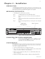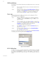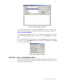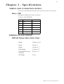
1
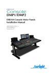
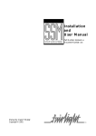
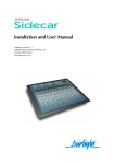
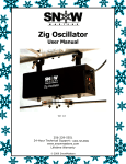
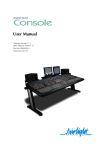
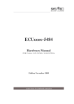
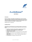
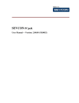
SMP1
Station Main Meter Panel
Installation Manual
DREAM Software Version: 1.1
Part No: DBE1104-A
Document No: 214
i
Important Notice
COPYRIGHT
The material in this document is copyright to Fairlight ESP Pty Ltd, and may not be quoted or reproduced in any form without written permission from the company.
Fairlight is a trademark of Fairlight ESP Pty Ltd. All other trademarks are the property of their respective owners.
LIMITED WARRANTY POLICY
All the software and hardware provided with, or purchased especially for, Fairlight products has been
tested for functionality. Fairlight ESP Pty Ltd will make its best efforts to correct reported defects for
future releases subject to technical practicabilities. Fairlight ESP will also replace any defective media
on which software has been delivered provided that the item to be replaced is returned to the dealer
who supported the product within 90 days of purchase.
Fairlight ESP Pty Ltd makes no warranty or representation either expressed or implied with respect
to the system's performance or fitness for a particular purpose.
In no event will Fairlight ESP Pty Ltd be liable for direct or indirect damages arising from any defect
in the product or its documentation. Further, Fairlight ESP Pty Ltd will not accept any liability for
any programs, sounds, audio recording or sequences stored in or used with Fairlight products, including the cost of recovery of such data.
The warranties, remedies and disclaimers above are exclusive and take precedence over all others, oral
or written, express or implied, to the extent permitted by law in the geographical area of the product's
use. No employee of Fairlight ESP, agent, distributor or employee of an agent or distributor is authorized to offer any variation from this policy.
Copyright © 2002
Fairlight ESP Pty Ltd,
Unit 2, 1 Skyline Place,
French's Forest, NSW 2086,
AUSTRALIA.
Telephone +61 2 8897 9999
Fax +61 2 8897 9900
ii
OBTAINING TECHNICAL SUPPORT
Users requiring technical support should contact their local Fairlight office or distributor. Information can also be found on the world wide web at:
http://www.fairlightesp.com
FAIRLIGHT OFFICES WORLD-WIDE
USA West Coast
Fairlight USA
844 North Seward Street,
Hollywood, CA90038
USA
Tel:+1 323 465 0070
Fax: +1 323 465 0080
United Kingdom
Fairlight ESP Limited
Unit 12, Spectrum House
32-34 Gordon House Road
London NW5 1LP
England
Tel: + 44-20-7267-3323
Fax: + 44-20-7267-0919
Germany
Fairlight Deutschland Gmbh
August-Bebel-Strasse 26-53
14482 Potsdam-Babelsberg
Berlin
Germany
Tel: +49 331 721 2930
Fax: +49 331 721 2933
USA East Coast
Fairlight USA
2 West 45th Street, Penthouse
New York, NY 10036
USA
Tel: +1 212 819 1289
Fax: +1 212 819 0376
France
Fairlight France
41-43 Rue des Peupliers
92100 Boulogne-Billancourt
Paris
France
Tel: +33 1 4610 9292
Fax: +33 1 4610 9295
Japan
Fairlight Japan Inc.
3-3-11 Ikejiri Setagaya-Ku
Tokyo
Japan 154-0001
Tel: +81 3 5432 4151
Freecall (Japan only): 0120 213 643
Fax: +81 3 5432 4533
Asia-Pacific
Fairlight ESP Pty. Ltd.
Unit 2, 1 Skyline Place,
Frenchs Forest NSW 2086
Australia
Tel: +61 2 8977 9999
Fax: +61 2 8977 9900
MANUAL ERRORS AND OMISSION
To help ensure that Fairlight provides the most accurate and comprehensive documentation, please report any errors or omissions to:
[email protected]
i
Table of Contents
Chapter 1: Introduction
INTRODUCTION. . . . . . . . . . . . . . . . . . . . . . . . . . . . . . . . . . . . . . . . . . . . . . . . . . . . . . . . . . . . . . 1-1
ABOUT THIS MANUAL . . . . . . . . . . . . . . . . . . . . . . . . . . . . . . . . . . . . . . . . . . . . . . . . . . . . . . . . . 1-1
USING THE STATION MAIN METER PANEL . . . . . . . . . . . . . . . . . . . . . . . . . . . . . . . . . . . . . . . . . 1-1
Chapter 2: Installation
INTRODUCTION. . . . . . . . . . . . . . . . . . . . . . . . . . . . . . . . . . . . . . . . . . . . . . . . . . . . . . . . . . . . . . 2-2
MECHANICAL INSTALLATION . . . . . . . . . . . . . . . . . . . . . . . . . . . . . . . . . . . . . . . . . . . . . . . . . . . 2-2
CONNECTING THE STATION METER PANEL . . . . . . . . . . . . . . . . . . . . . . . . . . . . . . . . . . . . . . . . 2-2
CONFIGURATION. . . . . . . . . . . . . . . . . . . . . . . . . . . . . . . . . . . . . . . . . . . . . . . . . . . . . . . . . . . . .
USB Installation . . . . . . . . . . . . . . . . . . . . . . . . . . . . . . . . . . . . . . . . . . . . . . . . . . . . . . . . . . . . . .
Cons-con . . . . . . . . . . . . . . . . . . . . . . . . . . . . . . . . . . . . . . . . . . . . . . . . . . . . . . . . . . . . . . . . . . .
LCD Calibration . . . . . . . . . . . . . . . . . . . . . . . . . . . . . . . . . . . . . . . . . . . . . . . . . . . . . . . . . . . . . .
2-2
2-3
2-3
2-3
TESTING AND COMMISSIONING. . . . . . . . . . . . . . . . . . . . . . . . . . . . . . . . . . . . . . . . . . . . . . . . . 2-4
Chapter 3: Specifications
WIRING AND CONNECTION DETAILS . . . . . . . . . . . . . . . . . . . . . . . . . . . . . . . . . . . . . . . . . . . . 3-2
Meter USB . . . . . . . . . . . . . . . . . . . . . . . . . . . . . . . . . . . . . . . . . . . . . . . . . . . . . . . . . . . . . . . . . . 3-2
DIMENSIONS AND WEIGHT. . . . . . . . . . . . . . . . . . . . . . . . . . . . . . . . . . . . . . . . . . . . . . . . . . . . . 3-2
DREAM Station Main Meter Panel . . . . . . . . . . . . . . . . . . . . . . . . . . . . . . . . . . . . . . . . . . . . . . . . 3-2
Index . . . . . . . . . . . . . . . . . . . . . . . . . . . . . . . . . . . . . . . . . . . . . . . . . . . . . . . . . . . . . . . . . . . . . . . . . . . i
TABLE OF CONTENTS
1-1
C h a p t e r 1 - I n t ro d u c t i o n
INTRODUCTION
The DREAM Station Main Meter Panel provides high resolution signal level metering for the Fairlight DREAM Station integrated mixer/editor. The Station is part
of a new family of products from Fairlight which marries together QDC processing
with an ergonomic physical control surface in a combination that has a significant
impact on productivity and efficiency. The Station and Station Sidecar combination offers a flexible and scaleable solution to a range of audio production and postproduction tasks.
ABOUT THIS MANUAL
The DREAM Station Meter Panel Installation Manual provides the information
necessary to install and operate the unit with a DREAM Station. This manual
should be used in conjunction with the DREAM Station Installation and User
Manual to obtain complete instruction in the use and installation of the complete
system.
This manual is designed to familiarize sound editors and engineers with the facilities
provided by the Station Main Meter Panel. The terminology and concepts used in
this manual assume a reasonable knowledge regarding audio principles and studio
procedures.
USING THE STATION MAIN METER PANEL
The Station Main Meter Panel includes eight, 55mm multi-segment bargraph LED
signal level meters, plus eight LCD meter legend windows. The Station Main Meter
Panel displays the signal level of each element of the Main bus. The name of each
element is displayed in the LCD window below each bargraph.
The number of active bargraphs is determined by the user-defined format of the
Main bus. For example, if the Main bus format is stereo, only LEFT and RIGHT
bus element meters are displayed. If the Main bus format is 7.1, all eight elements
are displayed. These are: LEFT, INNER LEFT, CENTRE, INNER RIGHT,
RIGHT, LEFT SURROUND, RIGHT SURROUND, BOOM.
The Station Main Meter Panel displays peak program level.
INTRODUCTION
2-1
NOTES:
2-2
Chapter 2 - Installation
INTRODUCTION
The DREAM Station Main Meter Panel is designed to be mounted directly to the
rear of the DREAM Station. One simple cable connection between the Station and
Meter Panel using the five pin XLR cable supplied, is also required.
MECHANICAL INSTALLATION
• Tools Required: 1 x #2 Pozi-drive screw driver
Step 1
Carefully unpack the Station Main Meter Panel.
Step 2
Remove the two screws on the rear of the Station as indicated
below.
Step 3
Align the Station Main Meter mounting brackets with the mounting holes.
Step 4
Fasten the mounting brackets by re-inserting the screws and tightening.
Meter Connector
Meter Panel
Mounting Screws
Model Number: Station
BE101126
Made in Australia
Manufactured in Sydney, Australia
by Fairlight ESP Pty. Ltd.
Warning: No user serviceable parts
inside. Refer service to authorised
Fairlight personnel.
Plugins I/O
PART15 CLASS A
Power Rating: AC 100 - 120V AC 200 - 240V
50 - 60 Hz 2A
Fuse Rating: F3.15A 250V
CAUTION: For continued protection against the risk of fire,
replace only with the same type and rating of fuse.
CAUTION: Disconnect power before changing fuse.
CDROM
Talkback
USB
Controller
GPI/GPO
VGA
Sidecar
Meter
PUSH
PUSH
Ethernet
Figure 1: Station Console Rear Panel Connections
CONNECTING THE STATION METER PANEL
Step 1
Connect the 5-pin XLR USB cable (part no. AMIX119-A) from
the female XLR labelled Meter on the rear of the Station to the
male XLR on the Station Main Meter Panel.
CONFIGURATION
If the Meter Panel has been purchased separately from the Station, the Station must
be configured to establish communication with the Meter Panel via USB. Follow
these steps to configure the Meter Panel:
1. Connect the Meter Panel prior to turning on the Station.
2. Turn on the Station. During start-up Windows will detect the new Meter Panel
hardware. Install the USB drivers as described below.
3. Run the console configuration utility Cons-con to add the Meter Panel to the
Station configuration.
4. Finally, run the FMC calibration utility to calibrate the Meter Panel LCDs.
INTRODUCTION
2-3
USB Installation
The USB driver for the Meter Panel must be installed the first time it is connected
to the system.
Step 1
Ensure the Meter Panel is connect to the Station and that the Station is running.
Step 2
During boot-up the Windows Found New Hardware dialog box
will appear. Click the Browse button and navigate to the following directory: C:\DREAM Drivers\USB drivers\W2000. Select
FairUsb.inf and click OK to complete the driver installation.
Cons-con
The Meter Panel must be added to the Station console configuration. This is
achieved with the Cons-con application.
Step 1
While the DREAM Start splash screen is displayed, hold down
the Shift key and press Pause/Break and type SU Enter to enter
super user mode.
Step 2
Use the trackball to click on the Binnacle Cut key to launch Conscon, the console configuration utility. Alternatively, click on My
Computer on the Windows desktop and navigate to
C:\Projects\mixers\fmc\system\Cons-con.exe.
Step 3
Select Station console type and click the Add Panel button to
add panels one at a time.
Step 4
Select panel number Panel 4, then select StationMainMeters
type. Click OK to add the panel.
To remove an accidentally added panel, select the panel and click Remove Panel.
To modify a panel, select the panel and click Modify Panel.
Figure 2: ConsCon Window
LCD Calibration
To calibrate the contrast on the Meter Panel LCD, run FMC. Hold down the Shift
key and press the Pause/Break key (Shift+Pause/Break toggles the keyboard focus
between FMC and the QDC engine) then type U. This will bring up the calibration
window.
INSTALLATION
2-4
Figure 3: Console Calibration Dialogue
The Meter Panels should be selected from the Panel drop down list and then calibrated as described below. If correctly entered in Cons-con, the panel is listed as
Panel 4, StationMainMeters.
Select LCD from the Type list. LCDs 1 to 4 are adjusted by LCD number 3, LCDs
5 to 8 are adjusted by LCD number 7. Select 3 or 7 from the Number list, then click
Go.
The LCD dialogue box will be displayed. Click the Contrast +/- buttons to change
the contrast. Click the Backlight +/- buttons to change the backlight level. Click OK
to move on to the next LCD.
Figure 4: LCD Calibration Window
TESTING AND COMMISSIONING
Once the Station Main Meter has been installed, configured and calibrated, refer to
the Station manual for operational procedures that will assist in testing its operation
within the studio environment.
TESTING AND COMMISSIONING
3-1
NOTES:
3-2
C h a p t e r 3 - S p e ci f i c at i o n s
WIRING AND CONNECTION DETAILS
Connector sex described is the panel mount connector on the rear of the unit.
Meter USB
Description: USB and DC Power connection.
Connector: 5 Pin XLR Male
XLR5
SIGNAL
PAIR
PIN 1
USB +
1
PIN 2
0V
PIN 3
12 V
PIN 4
0V
PIN 5
USB -
1
SHELL
SHIELD
1
DIMENSIONS AND WEIGHT
DREAM Station Main Meter Panel
Width
555 mm / 21.85”
Depth
50 mm / 2”
Height
120 mm / 4.7”
Fitted Height
215 mm / 8.5”
Fitted Depth from rear
of Station
85 mm / 3.4”
Net Weight
2.5 kg
WIRING AND CONNECTION DETAILS
Index - i
Index
A
Add Panel . . . . . . . . . . . . . . . . . . . 2-3
AMIX119-A . . . . . . . . . . . . . . . . . 2-2
C
Calibration . . . . . . . . . . . . . . . . . .
Configuration . . . . . . . . . . . . . . . .
Connecting . . . . . . . . . . . . . . . . . .
Cons-con . . . . . . . . . . . . . . . . . . .
2-3
2-2
2-2
2-3
D
Depth . . . . . . . . . . . . . . . . . . . . . . 3-2
Dimensions . . . . . . . . . . . . . . . . . . 3-2
DREAM Start . . . . . . . . . . . . . . . . 2-3
F
Fairlight Offices . . . . . . . . . . . . . . 3-ii
Found New Hardware . . . . . . . . . 2-3
H
Height . . . . . . . . . . . . . . . . . . . . . 3-2
L
LCD Calibration . . . . . . . . . . . . . . 2-3
M
Manual Errors and Omission . . . .
Mechanical Installation . . . . . . . . .
Meter . . . . . . . . . . . . . . . . . . . . . .
Modify Panel . . . . . . . . . . . . . . . .
3-ii
2-2
2-2
2-3
R
Remove Panel . . . . . . . . . . . . . . . . 2-3
S
Specifications . . . . . . . . . . . . . . . . 3-2
Station . . . . . . . . . . . . . . . . . . . . . 2-2
T
Technical Support . . . . . . . . . . . . . 3-ii
U
USB . . . . . . . . . . . . . . . . . . . . . . . 2-2, 3-2
USB Installation . . . . . . . . . . . . . . 2-3
Using the Meter Panel . . . . . . . . . 1-1
W
Weight . . . . . . . . . . . . . . . . . . . . . 3-2
Width . . . . . . . . . . . . . . . . . . . . . . 3-2
Wiring . . . . . . . . . . . . . . . . . . . . . 3-2
X
XLR . . . . . . . . . . . . . . . . . . . . . . . 2-2, 3-2
INDEX