1
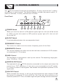
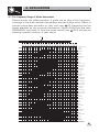
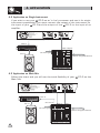
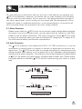
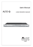
R
LTO
User's Manual
ALTO Q
5-BAND PARAMETRIC EQUALIZER
www.altoproaudio.com
Version 2.0 SEP. 2007
English
IMPORTANT SAFETY INSTRUCTION
CAUTION
RISK OF ELECTRIC SHOCK
DO NOT OPEN
TO REDUCE THE RISK OF ELECTRIC SHOCK
PLEASE DO NOT REMOVE THE COVER OR
THE BACK PANEL OF THIS EQUIPMENT.
THERE ARE NO PARTS NEEDED BY USER
INSIDE THE EQUIPMENT. FOR SERVICE,
PLEASE CONTACT QUALIFIED SERVICE
CENTERS.
WARNING
To reduce the risk of electric shock
and fire, do not expose this equipment
to moisture or rain.
Dispose of this product should
not be placed in municipal waste
and should be separate collection.
11. Move this Equipment only with a cart,
stand, tripod, or bracket,
This symbol, wherever used, alerts you to the
specified by the
presence of un-insulated and dangerous voltages
manufacturer, or
within the product enclosure. These are voltages that
sold with the
may be sufficient to constitute the risk of electric
Equipment. When
shock or death.
a cart is used, use
This symbol, wherever used, alerts you to
caution when
important operating and maintenance instructions.
moving the cart /
Please read.
equipment
Protective Ground Terminal
combination to
AC mains (Alternating Current)
avoid possible
Hazardous Live Terminal
injury from tip-over.
ON: Denotes the product is turned on.
12. Permanent hearing loss may be caused by
OFF: Denotes the product is turned off.
exposure to \ extremely high noise levels.
CAUTION
The US. Government's Occupational Safety
Describes precautions that should be observed to
and Health Administration (OSHA) has
prevent damage to the product.
specified the permissible exposure to noise
1. Read this Manual carefully before operation.
level.
2. Keep this Manual in a safe place.
These are shown in the following chart:
3. Be aware of all warnings reported
with this symbol.
HOURS X DAY SPL EXAMPLE
4. Keep this Equipment away from water and
90 Small gig
8
moisture.
92 train
6
5. Clean it only with dry cloth. Do not use
95 Subway train
4
solvent or other chemicals.
97 High level desktop monitors
3
6. Do not damp or cover any cooling opening.
100 Classic music concert
2
Install the equipment only in accordance with
102
the Manufacturer's instructions.
1,5
105
1
7. Power Cords are designed for your safety. Do
110
0,5
not remove Ground connections! If the plug
does not fit your AC outlet, seek advice from
0,25 or less 115 Rock concert
a qualified electrician. Protect the power
According to OSHA, an exposure to high SPL in
cord and plug from any physical stress to
excess of these limits may result in the loss of
avoid risk of electric shock. Do not place
heat. To avoid the potential damage of heat, it is
heavy objects on the power cord. This could
cause electric shock or fire.
recommended that Personnel exposed to
equipment capable of generating high SPL use
8. Unplug this equipment when unused for long
hearing protection while such equipment is
periods of time or during a storm.
under operation.
9. Refer all service to qualified service personnel
The apparatus shall be connected to a mains
only. Do not perform any servicing other than
those instructions contained within the
socket outlet with a protective earthing
User's Manual.
connection.
10. To prevent fire and damage to the product,
use only the recommended fuse type as
indicated in this manual. Do not short-circuit
the fuse holder. Before replacing the fuse,
make sure that the product is OFF and
disconnected from the AC outlet.
The mains plug or an appliance coupler is used
as the disconnect device, the disconnect device
shall remain readily operable.
IN THIS MANUAL:
1.
2.
3.
4.
5.
6.
7.
INTRODUCTION........................................................................1
FEATURES...............................................................................1
CONTROL ELEMENTS..............................................................2
APPLICATION..........................................................................4
INSTALLATION & CONNECTION.................................................7
TECHNICAL SPECIFICATIONS....................................................8
WARRANTY.............................................................................9
1. INTRODUCTION
Thank you for your purchasing of the LTO Q. The LTO Q is a 5-band
parametric equalizer. It provides precise audio signal control to fixed sound
installation, live performance and studio application.
The LTO Q includes 5 channels of equalization, the variable Q controls allow
you to notch out unwanted frequencies while sweepable frequency control add
maximum flexibility to your mix.
Enjoy your
LTO Q and make sure to read this Manual carefully before operation!
2. FEATURES
Illuminated Power Switch
Mountable in a 19" rack unit(1U)
1/4" TRS type jack and balanced XLR connectors available
LED Meter (12 LEDs) to read Input and Output
Low cut and High cut filters available to cancel unwanted frequencies
Bypass function to connect automatically Input and Output
Optimum transparency of the audio signal and minimum phase shift insured
by the parallel architecture of the filters
IN/OUT Switch on every single band
Constant Q principle combination
5 bands of equalization fully parametric (gain, frequency, Q) for studio and
live applications
The frequency range of the single 5-band is overlapping. This will allow extreme
boost or attenuation
1
SP
OT
L
IG
3.
3. CONTROL
CONTROLELEMENTS
ELEMENTS
HT
Your LTO Q includes 5 channels of equalization, 3 rotary controls and 1 switch
are present in each channel. The Master Section includes the power switch, 2
push-on switches, 3 rotary controls and 12 LEDs.
Front Panel:
11
2
BAND 5
1KHz - 20KHz
5.1
2.2
INPUT / OUTPUT LEVEL (dB)
IN// OUT
IN
10
30 24
18
12
6
3
3
0
6
9
12
I / O METER
OUT
IN
18
OUT
75
0
1.2
7.0
5
5
50
10
110
7
LTO Q
0
5
5
15
ON
12
1.3
1.0
20
KHz
FREQUENCY
3
10 25
10
0.03
1.6
OCTAVE
BANDWIDTH
4
15
15
200
3.5
10
400
22
2.5
30
10 AUDIO
IN
OUT
10
OFF
5-BAND
PARAMETRIC
EQUALIZER
15
15
dB
Hz
KHz
dB
LEVEL
LOW CUT
HIGH CUT
INPUT
5
7
8
9
POWER
6
1
1 POWER Switch
When you set this switch to ON position (green light on), the unit will be turned
on. When you set this switch to OFF position (green light off), the unit will
be turned off.
2 IN/OUT Switch
It activates/disactivates the correspondent band.
3 FREQUENCY Control
This control is used to set the center frequency point of the filter.
4 BANDWIDTH Control
This control adjusts the width and can be set from a minimum of 0.03 octaves
to a maximum of 1.6 octaves.
5 LEVEL Control
The level boost or attenuation is set by this control. The adjusting range goes
from -15 dB to +15 dB.
6 AUDIO IN/OUT Button
The input jack of your LTO Q is directly connected to the output jack when this
control is on "OUT" position or if the unit is not connected to the AC socket.
It is used to cause a "hard-bypass" and disable the equalization process in the
signal path.
7 LOW CUT Control
When activate this control, it will cut the low frequencies with a slope of 12 dB
per octave in a range of 10 Hz to 400 Hz. So if you set this control at the
maximum position of 10 Hz, the audio signal will pass through without alteration.
2
SP
OT
L
IG
3.
3. CONTROL
CONTROLELEMENTS
ELEMENTS
HT
8 HIGH CUT Control
When activate this control, it will cut the high frequencies with a slope of
12 dB per octave in a range of 2.5 kHz to 30 kHz. So if you set this control
at the maximum position of 30 kHz, the audio signal will pass through
without alteration.
9 INPUT Control
You can control the amount of the audio signal fed into your
control. The adjustable range goes from -15 dB to +15 dB.
LTO Q via this
10 INPUT/OUTPUT Meter Button
If you engage in this button, the LED Meter will read the output level, and
release this button, the LED Meter will read the input level.
11 INPUT/OUTPUT Level (LED Meter)
The readable range of this 12 segments LED display is -30 dB to +18 dB. As
mentioned before it will read either the INPUT or the OUTPUT level depending
on the position of the switch (10).
Rear Panel
Rated Power Consumption 9W
FUSE:
TIP/PIN 2
RING/PIN 3
SLEEVE/PIN 1
TIP/PIN 2
RING/PIN 3
SLEEVE/PIN 1
210-240V: T200mAL 250VAC
95-120V: T315mA 250VAC
REPLACE FUSE WITH CORRECT TYPE ONLY
Apparaten skall anslutas till
jordat uttag nar den ansluts
till ett natverk
A101
DESIGNED IN ITALY
MADE IN CHINA
12
OUTPUT
13
INPUT
14
12 AC Inlet and Fuse holder
Standard IEC receptacle. Connect your LTO Q to the AC with the supplied
AC power cord. Before powering up your LTO Q for the first time, make
certain the stated power requirement of the unit matches the voltage supplied
by the AC socket.
If the fuse blows, replaced with a fuse of the correct type only.
13 Output Connectors
The unit features Balanced XLR and 1/4" TRS jack output sockets which wired
in parallel. The Balanced signals are less sensitive to hum generated by AC.
14 Input Connectors
It also features Balanced XLR and 1/4" TRS jack input sockets which wired in
parallel. The Balanced signals are less sensitive to hum generated by AC.
3
3.
ELEMENTS
4. CONTROL
APPLICATION
4.1 The Frequency Range of Music Instruments
Please look at the following table. It gives you an idea of the frequency
coverage of the main musical instruments and the human voice. Select a
specific instrument and start to "play" with your LTO Q applying the five
bands available on the covered frequencies. Adjust GAIN first and then
FREQUENCY and finally Q. See how much control your LTO Q will give you
allowing a perfect contour of your sound.
Mid C
CDEFGABCDEFGABCDEFGABCDEFGABCDEFGABCDEFGABCDEFGABCDEFGABCDEFGABC
25
31
40
50
62
80 100 125 160 200 250 320 400 500 640 800 1K 1.3K1.6K 2K 2.5K3.1K 4K
5K 6.2K 8K 10K 13K 16K 20K
Human hearing range
VOCAL
Soprano
Contralto
Baritone
Bass
WOODWIND
Piccolo
Flute
Oboe
Clarinet in B flat or A
Clarinet in E flat
Bass Clarinet
Basset Hom
Cor Anglais
Bassoon
Double Bassoon
BRASS
Soprano Saxophone
Alto Saxophone
Tenor Saxophone
Baritone Saxophone
Bass Saxophone
Trumpet in C
Trumpet in F
Alto Trombone
Tenor Trombone
Bass Trombone
Tuba
Valve Hom
STRINGS
Violin
Viola
Cello
Double Bass
Guitar
KEYBOARDS
Pianoforte
Organ
PERCUSSION
Celesta
Timpani
Xylophone
25
31
40
50
62
80 100 125 160 200 250 320 400 500 640 800 1K 1.3K1.6K 2K 2.5K3.1K 4K
5K 6.2K 8K 10K 13K 16K 20K
FREQUENCY
4
3.
ELEMENTS
4. CONTROL
APPLICATION
4.2 Application on Single Instrument
If you wish to use your LTO Q as an "in line" processor and use it for single
instrument equalization, you must connect the output of the instrument to
the input of your LTO Q and the output of the LTO Q to the input of an
amplifier.
TIP/PIN 2
RING/PIN 3
SLEEVE/PIN 1
Rated Power Consumption 9W
FUSE:
TIP/PIN 2
RING/PIN 3
SLEEVE/PIN 1
210-240V: T200mAL 250VAC
95-120V: T315mA 250VAC
REPLACE FUSE WITH CORRECT TYPE ONLY
Apparaten skall anslutas till
jordat uttag nar den ansluts
till ett natverk
A101
INPUT
OUTPUT
DESIGNED IN ITALY
MADE IN CHINA
Output
Input
AMP IN
D1
SIG CLIP PROT
18
20
16
18
26
28
6
500W
SIG CLIP PROT
22
24
12
CH1
30 (dB)
16
20
2
Main Output
22
24
26
12
6
CH2
28
30 (dB)
AMP OUT
MIC level signal
SPK IN
Stereo Program Source
4.3 Application on Main Mix
Follow this chart and you will use the total flexibility of your
Main Mix.
TIP/PIN 2
RING/PIN 3
SLEEVE/PIN 1
Rated Power Consumption 9W
FUSE:
LTO Q on the
TIP/PIN 2
RING/PIN 3
SLEEVE/PIN 1
210-240V: T200mAL 250VAC
95-120V: T315mA 250VAC
REPLACE FUSE WITH CORRECT TYPE ONLY
Apparaten skall anslutas till
jordat uttag nar den ansluts
till ett natverk
A101
D1
SIG CLIP PROT
18
16
20
6
500W
SIG CLIP PROT
18
22
24
26
12
CH1
28
30 (dB)
16
20
INPUT
OUTPUT
DESIGNED IN ITALY
MADE IN CHINA
Output
Input
Return
Send
AMP IN
2
22
24
26
12
6
CH2
28
30 (dB)
AMP OUT
SPK IN
Main Output
MIC level signal
Stereo Program Source
5
3.
ELEMENTS
5. CONTROL
INSTALLATION
AND CONNECTION
Ok, you have got to this point and you are now in the position to operate your
LTO Q successfully. However, we advise you to read carefully the following
section to be the real master of your own mix. Not paying attention enough to
the input signal level, to the routing of the signal and the assignment of the
signal will result in unwanted distortion, a corrupted signal or no sound at all.
So you should follow this procedure for every single channel:
5.1 Mains Connection
Please ensure that the LTO Q is set to the correct supply voltage before plugging
the power cord into the wall outlet, use the same fuse as marked on the fuse
holder at the AC power connection. The mains connection of the LTO Q is made
by using the enclosed mains cord and a standard IEC receptacle. It meets all of
the international safety certification requirements.
5.2 Audio Connection
The LTO Q presents with balanced XLR & 1/4" TRS connectors. It can be
interfaced in several ways to support a variety of applications without any
signal loss. The LTO Q can be used on a single instrument by connecting to the
mixing console's main inserts, or on an entire mix "in-line" between a mixing console's
outputs and a power amplifier. The defective wiring may degrade the performance
of LTO Q, so please use good quality screened audio cables only. Please follow
the guide below to interface LTO Q without experiencing any noise or signal
loss.
Sleeve
Tip
Ring
Ring=Right Signal
Strain Clamp
Tip=Left Signal
Sleeve=Ground/Screen
Use for Headphone
1/4" Stereo (TRS) Jack Plug
Sleeve
Tip
Tip=Signal
Strain Clamp
Sleeve=Ground/Screen
Use for Mono Line In, Mono 1/4" Jack Plugs
1/4" Mono (TS) Jack Plug
6
3.
ELEMENTS
5. CONTROL
INSTALLATION
AND CONNECTION
Sleeve
Ring=Return Signal
Tip
Ring
Strain Clamp
Tip=Send Signal
Sleeve=Ground/Screen
Use for Insert Points
1/4" Stereo (TRS) Jack Plug
2=Hot(+)
2
3
1
2=Hot(+)
1=Ground/Screen
2
3
1
1=Ground/Screen
3=Cold(-)
3=Cold(-)
Use for Balanced Mic Inputs
(For unbalanced use, connect pin 1 to 3)
Use for Main output
(For unbalanced use, leave pin3 unconnected)
3-pin XLR Male Plug
3-pin XLR Line Socket
(seen from soldering side)
(seen from soldering side)
SLEEVE TIP
TIP RING SLEEVE
Tip
Ring
Sleeve
Tip (Send)
Sleeve
Tip (Return)
Sleeve
SLEEVE RING TIP
1
2 (Send)
1
3
2
Tip
Ring
Sleeve
2
1
2 (Return)
3
1
TIP RING SLEEVE
3
3
Tip
Ring
Sleeve
Centre (Send)
Screen
Centre (Return)
Screen
TIP RING SLEEVE
Insert Leads
5.3. RACK MOUNTING
The most secure mounting is on a universal rack shelf available from various rack
manufacturers or your Dealer. The 5-Band Parametric Equalizer fits into one
standard 19" rack unit of space. Be sure that there is enough air space around
the unit for sufficient ventilation and please do not place your 5-Band Parametric
Equalizer close to high temperature devices such as power amplifiers etc. to avoid
overheating.
7
6. TECHNICAL SPECIFICATION
Audio Input
Type
Impedance
Operating level
Maximum input level
CMRR
Audio Output
Type
Impedance
Maximum output level
System Specifications
Bandwidth
THD+N%
IMD
Noise
Frequency response
Low cut
High cut
Parametric Filter
Level
Frequency
Bandwidth
Function Switches
Audio IN/OUT
I/O meter IN/OUT
IN/OUT
Indicators
Input/output level
Function switch
Power Supply
Main voltages
Power consumption
Fuse
Physical
Dimension
Weight
Active balanced XLR and 1/4" JACK
Balanced: 50k Ohm/Unbalanced: 25k Ohm
+4 dBu/ 10 dBV
Balanced and Unbalanced: +18dBV
>55 dB @1k Hz
XLR and 1/4" JACK
Balanced: 60 Ohm / Unbalanced: 30 Ohm
+18 dBV
18 Hz to 30k Hz at 3 dBV
0.02% typ. 1k Hz, @+4 dBu / 0.04% typ. 1k Hz, @ 10 dBV
0.01% typ.
>-92 dBr unweighted 22 Hz to 22k Hz
18 Hz to 30k Hz, 3 dB
Variable (10 Hz to 400 Hz)
Variable (2.5k Hz to 30k Hz)
Variable ( 15 dB)
Band1: 20 Hz to 400 Hz/Band2: 60 Hz to 1k Hz
Band3: 150 Hz to 2.5k Hz / Band4: 500 Hz to 8k Hz
Band5: 1k Hz to 20k Hz
Variable (0.03 to 1.6 octaves)
Relay controlled hard bypass
Switches the meter display from input to output
Activates each filter band
12-segment LED display:
-30/-24/-18/-12/-6/-3/0/+3/+6/+9/+12/+18 dB
LED indicator of every switch
AC: 210 240 VAC~50 Hz
AC: 95 120 VAC~60 Hz
9 Watts
210 240V: T200mAL 250VAC
95 120V: T315mA 250VAC
483(W) 194.1(D) 44(H) mm
3.23 kg
8
7. WARRANTY
1. WARRANTY REGISTRATION CARD
To obtain Warranty Service, the buyer should first fill out and return the enclosed
Warranty Registration Card within 10 days of the Purchase Date.
All the information presented in this Warranty Registration Card gives the
manufacturer a better understanding of the sales status, so as to provide a
more effective and efficient after-sales warranty service. Please fill out all the
information carefully and genuinely, miswriting or absence of this card will void
your warranty service.
2. RETURN NOTICE
2.1 In case of return for any warranty service, please make sure that the
product is well packed in its original shipping carton, and it can protect your
unit from any other extra damage.
2.2 Please provide a copy of your sales receipt or other proof of purchase with
the returned machine, and give detail information about your return address
and contact telephone number.
2.3 A brief description of the defect will be appreciated.
2.4 Please prepay all the costs involved in the return shipping, handling and
insurance.
3. TERMS AND CONDITIONS
3.1 LTO warrants that this product will be free from any defects in materials
and/or workmanship for a period of 1 year from the purchase date if you
have completed the Warranty Registration Card in time.
3.2 The warranty service is only available to the original consumer, who purchased
this product directly from the retail dealer, and it can not be transferred.
3.3 During the warranty service, LTO may repair or replace this product at its
own option at no charge to you for parts or for labor in accordance with the
right side of this limited warranty.
3.4 This warranty does not apply to the damages to this product that occurred
as the following conditions:
Instead of operating in accordance with the user's manual thoroughly, any abuse
or misuse of this product.
Normal tear and wear.
The product has been altered or modified in any way.
Damage which may have been caused either directly or indirectly by another
product / force / etc.
Abnormal service or repairing by anyone other than the qualified personnel or
technician.
And in such cases, all the expenses will be charged to the buyer.
3.5 In no event shall LTO be liable for any incidental or consequential damages.
Some states do not allow the exclusion or limitation of incidental or
consequential damages, so the above exclusion or limitation may not apply to
you.
3.6 This warranty gives you the specific rights, and these rights are compatible
with the state laws, you may also have other statutory rights that may vary
from state to state.
9
SEIKAKU TECHNICAL GROUP LIMITED
NO. 1, Lane 17, Sec. 2, Han Shi West Road, Taichung 40151, Taiwan
http://www.altoproaudio.com Tel: 886-4-22313737
email: [email protected] Fax: 886-4-22346757
All rights reserved to ALTO. All features and content might be changed
without prior notice. Any photocopy, translation, or reproduction of part of this
manual without written permission is forbidden. Copyright c 2007 Seikaku Group