1
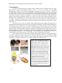
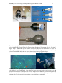
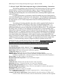
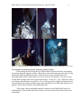
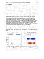
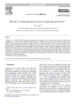
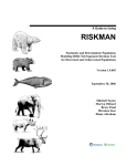
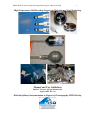
MISO- High-T self-recording fluid temperature loggers - Manual 8/25/06
1
High-Temperature Self-Recording Loggers for Hydrothermal Vent Monitoring
Manual and User Guidelines
Daniel J. Fornari ([email protected])
August 2006 Rev. 1.0
Multi-disciplinary Instrumentation in Support of Oceanography -MISO Facility
MISO- High-T self-recording fluid temperature loggers - Manual 8/25/06
2
1. Introduction
D. Fornari at WHOI helped to initially develop (with M. Olsson at DeepSea Power & LightDSPL) high-T ‘Hobo’ fluid temperature loggers (~152°C - 417°C) over a decade ago, and DSPL
provided them for many users in the oceanographic community for the past 10 years. These self
recording loggers (Figures 1 and 2) are rated to 6000 m operating depth and have been pressure certified
for use on Alvin. They have been used extensively and successfully at hydrothermal vents in the Pacific
and Atlantic Oceans by numerous investigators over the years and the results have been published in
numerous journal articles including: Fornari et al., [1996, 1998, 2003, 2004]; Fornari and Shank, [1999];
Langmuir et al., [1996]; Shank et al., [1998, 2001]; Sohn et al., [1998, 1999, 2005, in press]; Scheirer et
al., [2006]). These types of loggers are currently in use at the East Pacific Rise 9° 50’N and the Juan de
Fuca Ridge – Main Endeavour Field ISSs, and will be deployed in the Lau Basin in Fall, 2006 (C. Fisher,
Penn State. U.).
Over the past two years, since DSPL stopped manufacturing these loggers and turned over to
WHOI-MISO the drawings and related assembly and supplier information, I have provided refurbishment
and supply services to various users. Two styles of loggers exist, as shown in Figures 1 and 2. The most
recent (spherical housing) style has two Onset™ 32k recording chips, and a pressure barrier between the
housing and the tip, that provides shipboard capability for refurbishment and redeployment as long as
adequate supplies are on hand. The older style, cylindrical housings have been modified so that they now,
too accommodate two Onset™ 32k recording chips. The main difference is that the old style cannot be
refurbished at sea while the new ones can. The old style can be refurbished back at WHOI.
These loggers remain the only readily available, and relatively inexpensive self-recording high-T
vent fluid temperature loggers, and they have provided important time-series information to R2K
investigators working at various ISS sites. Most recently these loggers captured the 2005-2006 EPR
eruption at 9° 50’N (K. Von Damm, pers. commun., unpubl. data, 2006) (Figure 3).
B
A
C
D
F
E
E
Figure 1. New-style (spherical housing)
high-T logger. A) shows interior of spherical
housing with 2 Onset™ computer chips
(green wafers) visible. B) shows probe tip
and housing (quarter for scale reference). C)
RTD elements shown, lower one is raw RTD
and upper two are encased in ceramic plug.
D) loggers shown with polyethylene covers
which also serve to attach syntactic foam for
floatation. E-F) drawings of internal and
external views of spherical high-T loggers
showing location of Swage pressure fitting
that seals tubing from the housing where the
computer chips are stored. This
configuration provides the ability to service
the loggers at sea and replace tips that may
have had to be broken off in chimney walls.
In this case, the Ti tubing tips are replaced,
as are the RTD elements and connector, and
the unit can be placed back into service on
the same cruise.
MISO- High-T self-recording fluid temperature loggers - Manual 8/25/06
3
Figure 2. (top) Cylindrical (old-style) high-T fluid temperature loggers currently manufactured and
serviced by the MISO Facility. These loggers have been modified to accommodate two (2)- 32k Onset™
logging chips. When/if the tips are broken on recovery they must be returned to the facility for
machining, re-welding and re-certification and installation of new logging chips. (bottom) Old style
(cylindrical with MISO label) and new-style (spherical, gray housing) logger housings.
Figure 3. (left) New style logger (red arrow) imaged by TowCam on the R/V New Horizon cruise in M
vent, EPR at 9° 50.6’N in May 2006. Data from this logger (recovered by Alvin in June 06) provide the
first direct measurements of the impact of a volcanic eruption on hydrothermal vent fluid temperature (K.
Von Damm, unpubl. data, 2006) and the correlation with microseismicity [Tolstoy et al., submitted].
(right) An old-style logger being extracted from a vent with Jason2’s manipulator.
MISO- High-T self-recording fluid temperature loggers - Manual 8/25/06
4
2. ‘Old-style’ high-T MISO fluid temperature logger (cylindrical housing) - Instructions
The following guidelines and specifications are provided to help users in the operation
and maintenance of old-style fluid temperature loggers. Figure 4 shows the details of the
housing, end-cap, interior access to the connectors on the Onset™ 32k logging chips for
launching and downloading data, the serial download cable, and tubing bender supplied with
each set of loggers.
For optimal performance, new batteries should be installed just prior to deployment to
ensure the longest duration at cold bottom water temperatures. Even though the Li batteries that
power the Onset™ chips are rated to last ~5 yrs, de-rating by approximately half of that duration
for long exposure to 2-4°C bottom temperatures has been verified by numerous long
deployments.
The bending of the tubing should be done either with the supplied flexible bender in
order to prevent collapsing of the tubing or with a more conventional tubing bender. It is
suggested that you leave ~ 6-8” from the tip of the tubing straight to facilitate pre- or postdeployment calibrations where the tubing has to fit into the calibrator block. The wiring inside
the tubing ‘floats’ meaning it is not attached to the tubing interior so normal bending of the
tubing will not impact the wiring to the RTD element inside the end of the tube. Normally the
tubing is bent into a ‘J’ shape but variations to this are common depending on the morphology
and characteristics of the hydrothermal vents to be instrumented. It is strongly suggested that
you consult with the deep submergence vehicle pilots in regards to their suggestions for the
shape of the bend to be adopted. When ever possible the tubing should be bent under controlled
conditions on deck, not by the vehicle at depth. It is important to note that the scoring in the
tubing ~ 6” from the housing is meant to collapse the tubing to facilitate retrieval if the
instrument becomes cemented into the side of a vent chimney. The logger should be handled by
the vehicle’s manipulator from the tubing below the scoring or by the handle. Every effort
should be made not to flex the instrument so that stress is put on the scored tubing.
2.1. Specifications
Instrument model name: WHOI- MISO Hi-T Logger (old-style, cylindrical housing)
Instrument Description: Cylindrical Ti housing, 30” scored probe, NO pressure barrier
Depth rating: 6000 meters (Alvin pressure certification supplied)
Temperature range: 152°C to 417°C
Sampling rate: variable from 0.5 sec to hours, each chip programmed separately
Memory capacity: 64k total, using two (2) 8-bit, 32k Onset™ Computer Stowaway chips each
recording to one RTD sensor, conformal coating on chips and pressure tolerant components)
Energy supply: 3.6 VDC Li battery (5 year lifespan)
Duration of autonomous operation: ~2 years operational at depth
Accuracy: 2°C
Precision: 1°C
Calibration data: calibration data provided for 250°C, 300°C and 350°C
Dimensions: housing ~2” diameter, probe tip ~30” long (5/16” OD tubing)
Housing Weight (air/seawater): 0.6 kg (1.2 lb) in air, and 0.3 kg (0.6 lb) seawater
Instrument Weight (air/seawater): 1.4 kg (~3 lb) in air, just negative in seawater (with syntactic)
Housing material: titanium- Grade 2
Clock drift: estimated at <1 min over 12 months
Type of temperature sensor: RTDs (resistance temperature device) - 2 total per logger, both
embedded in ceramic plug
Computer and software requirements: Windows2000 PC with serial connector (or USB to serial
converter, Onset™ Boxcar® software, and serial download cable (software and cable supplied)
MISO- High-T self-recording fluid temperature loggers - Manual 8/25/06
A
5
B
D
C
E
F
Figure 4. (A) Old-style housing, syntactic foam handle, and endcap. Download cable - mini-RCA plug shown that connects to Onset™ logger chips in the housing. (B) Logger components: housing, end-cap,
serial download cable, tubing bender. Each housing is serialized as is the end-cap. (C) Close up of
housing insides, red arrow points to the connectors on each Onset™ recording chip. (D) Loggers ready
for deployment, note ‘J’ bend in left-most logger. Red arrow points to electrical tape used to ensure that
housing and handle do not unscrew. (E&F) Close-ups of scoring on the tubing (red arrows).
MISO- High-T self-recording fluid temperature loggers - Manual 8/25/06
6
2.2. Housing, End-caps, Tubing Tips and Seal Surfaces
Housings, end-caps and tubing tips are all made from Grade 2 Titanium. Welding of
tubing tips to housing is done in an oxygen-free environment. All seal surfaces have been
machined to tolerance and the entire housing is rated to 6000 m depth and certified for Alvin
operation. Each housing and end-cap is serialized and should be kept together. Seal surfaces in
the housing and the end-cap (Figure 4C) should be kept free from dirt/dust and lightly lubricated
with suitable Silicon O-ring grease prior to deployment. It is recommended that canned air be
sprayed into the housing just prior to sealing to ensure a moisture-free environment in the
housing during deployment. Tubing is scored (Figure 4E/F) to permit easy retrieval if cemented
in a vent chimney wall. See ‘Data Recovery’ section (2.7) for handling the Onset™ chip if the
tubing is broken and the housing floods at depth. The recorded data are normally OK and can be
downloaded if routine procedures are followed.
2.3. Onset™ 32k logger chips, RTD Temperature Sensors and Batteries
The logging chips are made by Onset Computer Corp. They are 8-bit, 32k StowAway
Temperature logger models with an external platinum RTD sensor that has a range of ~152°C to
417°C (Figure 5). Information about the Stowaway loggers can be found at:
(http://www.onsetcomp.com/Products/Product_Pages/older_data_loggers.html).
Figure 5. (left) Photo showing two Onset™ 32k memory chips used in the MISO loggers, the coil of
wires connected to the ceramic plug (red arrow) that contains two (2) platinum RTDs, and the battery
used in the chips. (right) Close-up of the RTDs encased in ceramic and the battery terminals. Battery
plugs into the Onset™ chip (red arrows) in one direction only because of offset in battery terminals and
their placement on the circuit board.
The platinum RTD sensor is specifically manufactured to measure temperatures in the
~152°C to 417°C range. Two RTDs are encased in high-temperature ceramic for each logger, to
prevent damage to the fine wires that connect them to the Onset™ chips (Figure 5).
Batteries supplied with the logger are Lithium/thionyl chloride made by Tadiran Batteries
Ltd. (Figure 5). They are user replaceable and can be ordered from: http://www.tadiranbat.com/
Care should be taken to properly dispose of the battery when normally discharged. Special
instructions are provided below in Section 2.7 when the casing is flooded at depth as hydrogen
and oxygen can be generated by electrolysis. MSDS sheets for these batteries are available at the
following link at: http://www.tadiranbat.com/primary.php.
MISO- High-T self-recording fluid temperature loggers - Manual 8/25/06
7
2.4. Launching the Logger and Downloading Data
The time on the Onset™ logging chips are set via the PC computer - BE SURE TO SET
THE TIME ON YOUR PC TO THE CORRECT DATE AND GMT TIME PRIOR TO
LAUNCHING THE LOGGERS.
The Onset™ logging chips are each launched via the serial cable that should be
connected to the small mini-RCA jacks on the chips in the housing, and a PC computer, with
Windows98™ or Windows2000™ operating system, running the Onset™ Boxcar® software
(Figure 6). Software has been provided with the loggers. Instructions for using the software are
provided in the user manual for Boxcar®. Additional information is available at the Onset™ site
at: http://www.onsetcomputer.com/, and for the BoxCar® software at:
http://www.onsetcomputer.com/Products/software_guide.html
It is suggested that care be taken when selecting the settings for recording data in terms of
whether the average, maximum or minimum temperature are selected to be recorded (green
arrow in Figure 6 (left). This set up can have important implications for interpretation of the
data.
When the logging chips are properly launched the small red LEDs visible in the housing
flash every few seconds. Check the Onset StowAway documentation for additional information.
Downloading the data is done via the same serial cable and the Boxcar® software. It is
strongly suggested that backups are made immediately of any data collected, and that the .dtf
formatted files (Boxcar® format) are converted to delimited text files for ease of importing into
other spreadsheet programs.
Figure 6. Screen grabs of Boxcar® software windows showing (left- red arrow) pull down menu for
selecting recording interval and and sampling options (green arrow). Right screen grab shows pop up
calendar (blue arrow) that appears when selecting ‘delayed start’ option. REMEMBER TO SET THE
COMPUTER DATE AND TIME TO GMT PRIOR TO LAUNCHING
2.5. Syntactic Handle -Buoyancy in Seawater
Figures 4A and 4D show the polyethylene handle with the syntactic foam block (1” thick
x 6” x 4”). The handle has a titanium, threaded rod (1/4-20 thread size) that is meant to screw
into the housing end-cap. Use of some waterproof - ‘never-seize’ ‘Aqualube™’ compound
(‘blue’ goop) is recommended. Several wraps of electrical tape should be used to tape handle to
the housing to prevent unscrewing (red arrow in Figure 4D). The syntactic foam provides
MISO- High-T self-recording fluid temperature loggers - Manual 8/25/06
8
adequate buoyancy in seawater for the logger to be slightly negative, so that the housing does not
‘fall out’ of the vent orifice after deployment.
2.6. Opening and Sealing the Housing
Rinse the housing well with fresh water after deployment and wipe dry with a soft cloth
or paper towels. The end cap is retained using a snap ring as shown in Figure 7. To remove the
snap ring, insert a small straight bladed screwdriver or a metal pick beneath the outer-end of the
snap ring (red arrow in Figure 7) and pull up to extract it from the groove in the housing. Once it
is out of the groove it can be gently pulled out in a spiral motion until it is free from the housing.
Use a ¼-20 threaded rod or the handle to remove the end cap. Care should be taken to not jam
the end cap or put it in the housing when it is tilted. It should be gently seated so it is flat and
then pushed down to get the end cap past the groove that retains the snap ring.
Figure 7. Left photo shows snap ring starting to be inserted into slot in the housing. Some times force
has to be used to keep the end-cap in position while inserting the snap ring. Right photo shows the snap
ring nearly inserted. Twist and guide the snap ring into the groove in the housing and make sure that the
ring is fully seated so that the end cap is retained. To remove the snap ring, insert the blade of a small
screwdriver and pull up the end of the snap ring and start unwinding it from the groove. It should come
out easily once started.
2.7. Deployment Suggestions
bending the tubing, labeling the handle
excavation, nearby chimneys, placement in the vent orifice, subsequent sampling at that
orifice…
MISO- High-T self-recording fluid temperature loggers - Manual 8/25/06
9
Figure 8. Examples of high-T logger deployments at hydrothermal vents at the EPR in the 9° 50’N area.
2.8. Data Recovery and Precautions if Housing Floods at Depth
If the housing floods because the tip is broken during extraction from the vent chimney
the housing should be opened carefully. Immediately remove the battery from the Onset™ chip
and discard following MSDS procedures. Rinse the Onset chip in distilled fresh water
thoroughly and let dry in a fume hood or in a clean, dust free environment. You can use a low
wattage bulb to supply some heat to speed up the drying. Let dry for ~1 day. When dry, insert a
new battery (short the battery terminals for 1-2 sec with a screwdriver blade- that helps starts the
current flowing in the battery) and the logger chip should blink its red LED light when power is
applied. Then connect to the PC and download the data.
The housing, end-cap and handle should be returned to the WHOI MISO facility for
refurbishment. Please include the Onset™ chip as well for evaluation after the data have been
downloaded.
MISO- High-T self-recording fluid temperature loggers - Manual 8/25/06
10
2.9. Calibration
Calibration of the loggers is done using an IEEE calibrated oven and an Omega
hand held thermometer with a thermocouple probe that was also inserted into the oven
block. Each Onset™ chip in each logger housing is set to record at the same time
intervals using the delay function in the Onset™ Boxcar® software. Recording periods
for calibration runs vary but are usually fast- 1-2 seconds. All PC clocks are set to GMT
- the Onset™ chip takes its time from the PC clock when launched so it is important to be
sure you set your computer’s clock to GMT prior to launching the logger.
Calibration is normally done at several set temperatures, e.g., 200°C, 250°C, 300°C and
350°C for ~10 minutes (see Figure 9). Previous testing by plunging the hot tips into ice
baths indicated that the response time of the RTD sensors is within a few seconds.
The temperature recorded by the handheld thermometer is also logged at the same
interval as the logger. Tests done using the handheld thermometer indicate that the
calibrator block is within a few degrees of the set temperature. Because there are 3 holes
in the block, and variations occur when the loggers are inserted and removed from the
calibrator, the temperature of the calibrator is usually a few degrees below the set
temperature. Logger temperatures are normally very consistent (within ~ 1-2°C) once the
calibrator equilibrates by having the logger in the block for ~5-10 min.
For each logger, data from the two chips are provided as both .dtf (Onset™Boxcar®
format) and .txt saved as Excel with the header information for each Onset™ chip
preserved, and the file name including the serial number of the chip. A plot of the
temperature data for each logger is usually saved as a .png or .jpg file and provided to the
user.
Figure 9. Example calibration data from MISO high-T logger s/n114. Note consistency of the readings
despite the 3-4°C offset due to logger tip placement in the calibrator and positioning of the RTDs with
respect to other openings in the calibrator block. Right plot shows detail of the 350°C calibration.
MISO- High-T self-recording fluid temperature loggers - Manual 8/25/06
11
3. ‘New-style’ high-T MISO fluid temperature logger (spherical housing) - Instructions
**TO BE WRITTEN along same style as old logger**
MISO- High-T self-recording fluid temperature loggers - Manual 8/25/06
12
Journal citations for published research using the high-T and low-T Loggers
Fornari, D.J., F. Voegeli, and M. Olsson, Improved low-cost, time-lapse temperature loggers
for deep ocean and sea floor observatory monitoring, RIDGE Events, 7, 13-16, 1996.
Fornari, D.J., T.M. Shank, K.L. Von Damm, T.K.P. Gregg, M. Lilley, G. Levai, A. Bray,
R.M. Haymon, M.R. Perfit, and R.A. Lutz, Time-series temperature measurements at
high-temperature hydrothermal vents: East Pacific Rise 9°49'N jto 9°51'N: Monitoring
dike intrusion and crustal cracking events, Earth and Planet. Sci. Lett., 160, 419-431,
1998.
Fornari, D.J. and T.M. Shank, Summary of high- and low-T time-series vent fluid
temperature experiments East Pacific Rise Vents 9° 49’-51’N, EXTREME-1 Cruise,
May, 1999, R/V Atlantis Cruise 03-34, July 1, 1999 (cruise report).
Fornari, D.J., Tivey, M.A., Schouten, H., et al., Submarine Lava Flow Emplacement at the
East Pacific Rise 9° 50´N: Implications for Uppermost Ocean Crust Stratigraphy and
Hydrothermal Fluid Circulation, in: Thermal Structure of the Ocean Crust and the
Dynamics of Hydrothermal Circulation, AGU Geophysical Monograph 148, C.
German et al., eds., 187-217, 2004.
Humphris, S.E., D.J. Fornari, D.S. Schierer, C. German, L. Parson, Geotectonic Setting
of Hydrothermal Activity on the Summit of Lucky Strike Seamount (37°17'N, MidAtlantic Ridge), Geophysics, Geochemistry, Geosystems, 10.1029/2001GC000284,
2002.
Langmuir, C.H., Humphris, S.E., Fornari, D., Van Dover, C.L., Von Damm, K. Tivey,
M.K., Colodner, D., Charlou, J.L., Desonie, D., Wilson, C., Fouquet, Y., Klinkhammer,
G. and Bougault, H., 1995. Description and significance of hydrothermal vents near a
mantle hot spot: the Lucky Strike vent field at 37°N, Mid-Atlantic Ridge, Earth Planet.
Sci. Lett., 148, 69-91.
Scheirer, D.S., T.M. Shank, and D.J. Fornari, Temperature variations at diffuse and focused
flow hydrothermal vent sites along the Northern East Pacific Rise, G3ed, 2006 (in press).
Shank, T.M., D.J. Fornari, K.L. Von Damm, M. Lilley, R.M. Haymon, and R.A. Lutz,
Temporal and Spatial Patterns of Biological Community Development at Nascent DeepSea Hydrothermal Vents along the East Pacific Rise, Deep Sea Res., 45, 465-515, 1998.
Shank, T.M., D.S. Scheirer, and D. Fornari, Time Series Studies of Faunal Colonization and
Temperature Variations at Diffuse-Flow Hydrothermal Vent Sites Near 9°50'N, EPR, Eos
Trans. AGU, 82, 196, 2001.
Sohn, R.A., D. Fornari, K.L. Von Damm, J.A. Hildebrand, and S.C. Webb, Seismic and
hydrothermal evidence for a cracking event on the East Pacific Rise crest at 9°50'N,
Nature, 396, 159-161, 1998.
Sohn, R.A., J.A. Hildebrand, and S.C. Webb, A microearthquake survey of the hightemperature vent fields on the volcanically active East Pacific Rise, J. Geophys. Res., 104
(11), 25,367-25,378, 1999.
Sohn, R.A., S.A. Humphris, J. Canales, Stochastic Analysis of Exit-Fluid Temperature
Time-Series Data from the TAG Hydrothermal Mound: Events, States, and Hidden
Markov Models, Am. Geophys. Union, Eos, 86(52), OS22A-06, 2005.