1
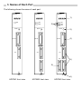
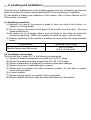
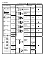
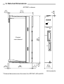
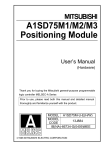
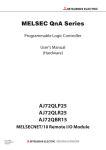
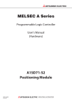
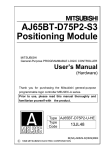
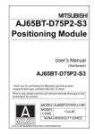
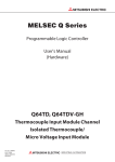
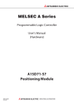
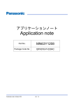
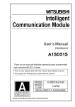
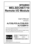
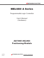
MITSUBISHI ELECTRIC
MELSEC A Series
Programmable Logic Controller
User's Manual
(Hardware)
AD75M1/M2/M3
Positioning Module
01 10 2001
IB(NA)66735
Version E
MITSUBISHI ELECTRIC
INDUSTRIAL AUTOMATION
! SAFETY PRECAUTIONS !
(Always read before starting use)
When using Mitsubishi equipment, thoroughly read this manual and the
associated manuals introduced in this manual. Also pay careful attention to
safety and handle the module properly.
These precautions apply only to Mitsubishi equipment. Refer to using CPU
module user's manual for a description of the PLC system safety precautions.
These !SAFETY PRECAUTIONS! classify the safety precautions into two
categories: "DANGER" and "CAUTION".
DANGER
Procedures which may lead to a dangerous condition and
cause death or serious injury if not carried out properly.
Procedures which may lead to a dangerous condition and
CAUTION cause superficial to medium injury, or physical damage
only, if not carried out properly.
Depending on circumstances, procedures indicated by
be linked to serious results.
CAUTION may also
In any case, it is important to follow the directions for usage.
Store this manual in a safe place so that you can take it out and read it
whenever necessary. Always forward it to the end user.
[DESIGN PRECAUTIONS]
DANGER
! Configure a safety circuit so that the safety of the overall system is maintained
even when an external power error or PLC error occurs.
An accident may occur by a false output or a malfunction.
(1) Outside of the PLC, construct mechanical damage preventing interlock circuits
such as emergency stop, positioning upper and lower limit switches.
(2) During zero return operation, the module is controlled by two data: zero return
direction and zero return speed, and speed begins to decelerate when the near
point dog turns on. If the zero return direction is set incorrectly, the module
may continue to operate without decelerating. To prevent damage to the
module in such cases, configure an interlock circuit outside the PLC.
CAUTION
! Do not bunch the control wires or communication cables with the main circuit or
power wires, or install them close to each other.
They should be installed 100 mm (3.9 inch) or more from each other.
Not doing so could result in noise that would cause malfunction.
[INSTALLATION PRECAUTIONS]
CAUTION
! Use the PLC in an environment that meets the general specifications contained in
this manual.Using this PLC in an environment outside the range of the general
specifications could result in electric shook, fire, malfunction, and damage to or
deterioration of the product.
! Insert the tabs at the bottom of the module into the mounting holes in the base
module, and tighten the screws using the specified torque.
If the module is not properly installed, it may result in malfunctions, failure, or
fallout.
! Verify that the external device connector, SSCNET connector and RS-422
connector are securely attached to the connectors on the module. Confirm that
they connect with an audible click.
If not attached properly, a contact error may occur, resulting in incorrect input or
output.
! Always attach a cover to connectors that are not used. If not covered,
malfunctions may occur.
! Do not directly touch the module's conductive parts or electronic components.
Doing so could cause malfunction or failure in the module.
[WIRING PRECAUTIONS]
CAUTION
! Be sure there are no foreign substances such as sawdust or wiring debris inside
the module.
Such debris could cause fires, failure, or malfunction.
! Perform soldering of the external device connector and SSCNET connector after
verifying the pin layout.
! Perform soldering of those connectors correctly. False soldering may cause short
circuits and malfunctions.
[STARTUP AND MAINTENANCE PRECAUTIONS]
DANGER
! Make sure to switch all phases of the external power supply off before cleaning.
If you do not switch off the external power supply, it will cause malfunctions of the
module.
! Do not disassemble or modify the modules. Doing so could cause failure,
malfunction, injury, or fire.
! Make sure to switch all phases of the external power supply off before mounting or
removing the module. If you do not switch off the external power supply, it will
cause failure or malfunction of the module.
! Remove the external device connector and SSCNET connector after the system
has been stopped.
The system will stop if they are removed while the system is running.
! When performing test operation, set the parameter for the speed limit value to a
slow setting and prepare for an immediate stop of the module should a dangerous
condition occur during operation verification.
[USAGE PRECAUTIONS]
CAUTION
! Exercise caution when the reference-axis speed for interpolation operation has
been specified, since the speed of the opposite axis (second axis) can get greater
than the set speed (speed limit value).
[DISPOSAL PRECAUTIONS]
CAUTION
! When disposing of this product, treat it as industrial waste.
About the Manuals
The following product are available for this equipment.
Refer to the table given below to choose suitable manuals.
Detailed Manual
Manual name
Positioning module type A1SD75M1/M2/M3, AD75M1/M2/M3
User's Manual
Manual No.
(Model code)
IB-66715
(13J870)
Related Manual
Manual name
Positioning module software package
type SW1IVD-AD75P Operating Manual
GX Configurator-AP Version 1 Operating Manual
Manual No.
(Model code)
IB-66714
(13J915)
IB-66900
(13J948)
Correspondence to EMC DIRECTIVE
For instructions to make the PLC compatible with EMC standards, refer to "EMC
AND LOW-VOLTAGE DIRECTIVE" in PLC CPU User's Manual (Hardware).
* When the PLC CPU user's manual (Hardware) does not include Chapter 3 "EMC
AND LOW-VOLTAGE DIRECTIVE", refer to QnA Series CPU Compatible HighSpeed Accessing Basic Base Unit-Additional Explanation for Product Conforming to
EMC Standards (IB-68837) (optional).
1. Overview
This manual describes how to install AD75M1/M2/M3 Positioning Module (hereafter
abbreviated as AD75) and how to wire them with external devices.
After unpacking AD75, please confirm that the following products are contained.
Product name
AD75M1 Positioning Module
AD75M2 Positioning Module
AD75M3 Positioning Module
Connector
(10136-3000VE)
External device connector
(Model)
Connector cover
(10336-56F0-008)
Quantity
1
1
1
1
2
3
1
2
3
2. Performance Specifications
The performance specifications for the AD75 are shown below.
Item
Maximum output command
speed
Maximum connection distance
between servos
Number of occupied I/O points
Internal current consumption
Flash ROM write counts
Access counts to the FeRAM
when the absolute position
detection system is employed
External dimensions (mm)[inch]
Weight (kg)[lb]
Specifications
1Mpps
Overall distance of SSCNET cable: 30m (98.43 ft.)
32 points
5VDC, 0.7A or less
Max. 100,000 times
Max. 9,999,900,000 times
250[9.84](H)×37.5[1.48](W)×106[4.17](D)
0.45[0.99]
3. Names of Each Part
The following shows the name of each part.
AD75M1
AD75M2
AD75M3
1)
AX1
AX1
AX2
MODE
MODE
RS-422
3)
MODE
RS-422
AX1
AX1
AX2
AX3
2)
4)
RS-422
AX1
AX1
AX2
AX3
AX2
5)
5)
FRONT
FRONT
SSCENT
FRONT
SSCENT
SSCENT
6)
AD75M1 front view
AD75M2 front view
AD75M3 front view
No.
1)
Name
17-segment LED
2)
Axis display LEDs
AX1 to 3
Mode switch
3)
4)
5)
RS-422 connector
External device
connector
Description
• Indicates the operation status.
• When the mode switch is pressed, it displays a
message for the selected mode.
• Indicate the status of respective axes based on the
message displayed on the 17-segment LED.
• A selector switch that changes the mode.
• The mode is changed each time the switch is
pressed.
• Connector for connection to peripheral device.
• Connector for mechanical system input or manual
pulsar.
The applicable wire size for the connector is AWG #24
to #30 (0.05 to 0.2).
The pin layout for the included external device
connector is as follows. Perform wiring according to
the interface.
2
20
19
1
Wire
18
SSCNET connector
35
36
17
6)
Solder
The pin layout viewed from the top is shown.
The connector pins are referred to as 1 to 36.
Connector for SSCNET-compatible servo amplifier
4. Loading and Installation
The following is explanations of the handling precautions and installation environment
which is common to modules when handling AD75 from unpacking to installation.
For the details of loading and installation of the module, refer to User's Manual of PLC
CPU module to be used.
4.1 Handling precautions
(1) Because the case of the module is made of resin, be careful not to drop it or
expose it to strong impact.
(2) Do not remove the printed circuit board of the module from the case. This may
cause malfunctions.
(3) Be careful not to let foreign matters such as filings or wire chips get inside the
module during wiring. When such matters do enter, be sure to remove them.
(4) Execute tightening of the module's installation screws within the range indicated
below.
Screw position
Module fixing screw (M4 screw)
Tightening torque range
78 to 118 Ncm
(6.9 to 10.4 lb•inch)
4.2 Installation environment
Do not install the A series PLC in the following environments.
(1) Where the ambient temperature exceeds the 0 to 55°C range.
(2) Where the ambient humidity exceeds the 10 to 90 % RH range.
(3) Where condensation is produced by sudden temperature changes.
(4) Where corrosive or combustible gas is present.
(5) Where dust, iron powder and other conductive powder, oil mist, salt, or organic
solvents are prevalent.
(6) In direct sunlight.
(7) Where a strong electric or magnetic field is generated.
(8) Where vibration and shock may be transmitted directly to the module.
5. Wiring
Precautionary notes when wiring as well as the interface are described below.
5.1 Precautionary notes when wiring
This section describes the precautionary notes for the wiring process between the
AD75 and outside (servo amplifier).
(1) Signal wiring
(a) Do not bundle I/O signal wires with, or lay them close to, power lines or main
circuit lines.
(b) If I/O signal wires have to be laid close to these lines, either use a partitioned
duct or separate conduits.
(c) If there is no alternative but to bundle the cables together, use a shielded
cable and ground its shielding at the PLC CPU side.
(d) If conduits are used for wiring, ground the conduits.
(e) If the connecting cable is too long, or is too close to a main circuit line,
malfunctions could occur due to noise.
(2) Fitting connectors to the AD75
(a) Make sure that the external device connector, connector for connection to the
SSCNET, and connector for connecting the peripheral device, are securely
engaged with the corresponding connector at the AD75, and have clicked into
place.
If the connector is not engaged securely the contact will be defective, and this
could cause erroneous inputs and outputs.
(b) Disconnect the external device connector and SSCNET connector while the
system is stopped.
If these connectors are disconnected while the system is in operation, the
system will stop.
Note) Refer to Servo Amplifier Instruction Manual for the cable and terminal
connector that are required for connection to a servo amplifier in SSCNET.
5.2 Interface
" : Wiring required
External wiring
When the high
limit LS is not
used
Pin
number
11
Near-point
dog signal
DOG
12
High limit LS
signal
FLS
"
13
Low limit LS
signal
RLS
"
14
Stop signal
STOP
15
Speed/
position
switch signal
CHG
16
External
start signal
STRT
Common
COM
When the low
limit LS is not
used
24VDC
Internal circuit
: Wiring performed as required
Wiring
Signal name
requirement
35
36
5V
5VDC
A
(+)
9
(-)
27
Manual
pulser
phase A
PULSER
A+
PULSER
A-
B
OV
Manual pulser
(MR-HDP01)
(+)
10
(-)
28
Manual
pulser
phase B
PULSER
B+
PULSER
B-
"
6. External Dimensions
AD75M1 is shown.
111
(4.37)
2
(0.08)
4.2
(0.17)
A D75M1
AX1
MODE
RS-422
250
(9.84)
Printed
circuit board
AX1
FRONT
4.2
(0.17)
106
(4.17)
5.3
(0.21)
SSCENT
3
(0.12)
37.5
(1.48)
Unit:mm(inch)
* External dimensions are the same for AD75M1, M2 and M3.
Warranty
Mitsubishi will not be held liable for damage caused by factors found not to be the cause of
Mitsubishi; machine damage or lost profits caused by faults in the Mitsubishi products;
damage, secondary damage, accident compensation caused by special factors
unpredictable by Mitsubishi; damages to products other than Mitsubishi products; and to
other duties.
For safe use
# This product has been manufactured as a general-purpose part for general industries, and
has not been designed or manufactured to be incorporated in a device or system used in
purposes related to human life.
# Before using the product for special purposes such as nuclear power, electric power,
aerospace, medicine or passenger movement vehicles, consult with Mitsubishi.
# This product has been manufactured under strict quality control. However, when installing
the product where major accidents or losses could occur if the product fails, install
appropriate backup or failsafe functions in the system.
Country/Region Sales office/Tel
U.S.A
Mitsubishi Electric Automation Inc.
500 Corporate Woods Parkway Vernon
Hills, IL 60061
Tel : +1-847-478-2100
Brazil
MELCO-TEC Rep. Com.e Assessoria
Tecnica Ltda.
Av. Rio Branco, 123-15 ,and S/1507,
Rio de Janeiro, RJ CEP 20040-005,
Brazil
Tel : +55-21-221-8343
Germany
Mitsubishi Electric Europe B.V. German
Branch
Gothaer Strasse 8 D-40880 Ratingen,
GERMANY
Tel : +49-2102-486-0
U.K
Mitsubishi Electric Europe B.V. UK
Branch
Travellers Lane, Hatfield, Herts., AL10
8XB,UK
Tel : +44-1707-276100
Italy
Mitsubishi Electric Europe B.V. Italian
Branch
Centro Dir. Colleoni, Pal. Perseo - Ingr.2
Via Paracelso 12, 20041 Agrate B.,
Milano, Italy
Tel:+39-039-6053301
Spain
Mitsubishi Electric Europe B.V. Spanish
Branch Carretera de Rubi 76-80
08190 - Sant Cugat del Valles,
Barcelona, Spain
Tel:+34-935-653135
South Africa
Circuit Breaker Industries LTD.
Private Bag 2016, Isando 1600,
Johannesburg, South Africa
Tel : +27-11-928-2000
Hong Kong
Ryoden International Ltd.
10th Floor, Manulife Tower, 169 Electric
Road, North Point, HongKong
Tel : +852-2887-8870
Country/Region Sales office/Tel
China
Ryoden International Shanghai Ltd.
3F Block5 Building Automation
Instrumentation Plaza 103 Cao Bao Rd.
Shanghai 200233 China
Tel : +86-21-6475-3228
Taiwan
Setsuyo Enterprise Co., Ltd.
6F., No.105 Wu-Kung 3rd.RD, Wu-Ku
Hsiang, Taipei Hsine, Taiwan
Tel : +886-2-2299-2499
Korea
HAN NEUNG TECHNO CO.,LTD.
1F Dong Seo Game Channel Bldg.,
660-11, Deungchon-dong Kangsec-ku,
Seoul, Korea
Tel : +82-2-3668-6567
Singapore
Mitsubishi Electric Asia Pte, Ltd.
307 ALEXANDRA ROAD #05-01/02,
MITSUBISHI ELECTRIC BUILDING
SINGAPORE 159943
Tel : +65-473-2480
Thailand
F. A. Tech Co.,Ltd.
898/28,29,30 S.V.City Building,Office
Tower 2,Floor 17-18 Rama 3 Road,
Bangkpongpang, Yannawa,
Bangkok 10120
Tel : +66-2-682-6522
Indonesia
P.T. Autoteknindo SUMBER MAKMUR
Jl. Muara Karang Selatan Block A Utara
No.1 Kav. No.11 Kawasan Industri/
Pergudangan Jakarta - Utara 14440
Tel : +62-21-663-0833
India
Messung Systems Put,Ltd.
Electronic Sadan NO:111 Unit No15,
M.I.D.C BHOSARI,PUNE-411026
Tel : +91-20-7128927
Australia
Mitsubishi Electric Australia Pty. Ltd.
348 Victoria Road, PostalBag, No 2,
Rydalmere, N.S.W 2116, Australia
Tel : +61-2-9684-7777
HEAD OFFICE : 1-8-12, OFFICE TOWER Z 14F HARUMI CHUO-KU 104-6212, JAPAN
NAGOYA WORKS : 1-14, YADA-MINAMI5, HIGASHI-KU, NAGOYA, JAPAN
When exported from Japan, this manual does not require application to the Ministry
of Economy, Trade and Industry for service transaction permission.
Specifications subject to change without notice.
Printed in Japan on recycled paper.
MITSUBISHI ELECTRIC
HEADQUARTERS
EUROPEAN REPRESENTATIVES
EUROPEAN REPRESENTATIVES
MITSUBISHI ELECTRIC EUROPE B.V.
EUROPE
German Branch
Gothaer Straße 8
D-40880 Ratingen
Phone: +49 (0)2102 / 486-0
Fax: +49 (0)2102 / 486-1120
MITSUBISHIELECTRICEUROPEB.V.-org.sl. CZECH REP.
Czech Branch
Avenir Business Park, Radlická 714/113a
CZ-158 00 Praha 5
Phone: +420 - 251 551 470
Fax: +420 - 251-551-471
MITSUBISHI ELECTRIC EUROPE B.V.
FRANCE
French Branch
25, Boulevard des Bouvets
F-92741 Nanterre Cedex
Phone: +33 (0)1 / 55 68 55 68
Fax: +33 (0)1 / 55 68 57 57
MITSUBISHI ELECTRIC EUROPE B.V.
IRELAND
Irish Branch
Westgate Business Park, Ballymount
IRL-Dublin 24
Phone: +353 (0)1 4198800
Fax: +353 (0)1 4198890
MITSUBISHI ELECTRIC EUROPE B.V.
ITALY
Italian Branch
Viale Colleoni 7
I-20041 Agrate Brianza (MB)
Phone: +39 039 / 60 53 1
Fax: +39 039 / 60 53 312
MITSUBISHI ELECTRIC EUROPE B.V.
POLAND
Poland Branch
Krakowska 50
PL-32-083 Balice
Phone: +48 (0)12 / 630 47 00
Fax: +48 (0)12 / 630 47 01
MITSUBISHI ELECTRIC EUROPE B.V.
RUSSIA
52, bld. 3 Kosmodamianskaya nab 8 floor
RU-115054 Мoscow
Phone: +7 495 721-2070
Fax: +7 495 721-2071
MITSUBISHI ELECTRIC EUROPE B.V.
SPAIN
Spanish Branch
Carretera de Rubí 76-80
E-08190 Sant Cugat del Vallés (Barcelona)
Phone: 902 131121 // +34 935653131
Fax: +34 935891579
MITSUBISHI ELECTRIC EUROPE B.V.
UK
UK Branch
Travellers Lane
UK-Hatfield, Herts. AL10 8XB
Phone: +44 (0)1707 / 27 61 00
Fax: +44 (0)1707 / 27 86 95
MITSUBISHI ELECTRIC CORPORATION
JAPAN
Office Tower “Z” 14 F
8-12,1 chome, Harumi Chuo-Ku
Tokyo 104-6212
Phone: +81 3 622 160 60
Fax: +81 3 622 160 75
MITSUBISHI ELECTRIC AUTOMATION, Inc.
USA
500 Corporate Woods Parkway
Vernon Hills, IL 60061
Phone: +1 847 478 21 00
Fax: +1 847 478 22 53
GEVA
AUSTRIA
Wiener Straße 89
AT-2500 Baden
Phone: +43 (0)2252 / 85 55 20
Fax: +43 (0)2252 / 488 60
TEHNIKON
BELARUS
Oktyabrskaya 16/5, Off. 703-711
BY-220030 Minsk
Phone: +375 (0)17 / 210 46 26
Fax: +375 (0)17 / 210 46 26
ESCO DRIVES & AUTOMATION
BELGIUM
Culliganlaan 3
BE-1831 Diegem
Phone: +32 (0)2 / 717 64 30
Fax: +32 (0)2 / 717 64 31
Koning & Hartman b.v.
BELGIUM
Woluwelaan 31
BE-1800 Vilvoorde
Phone: +32 (0)2 / 257 02 40
Fax: +32 (0)2 / 257 02 49
INEA BH d.o.o.
BOSNIA AND HERZEGOVINA
Aleja Lipa 56
BA-71000 Sarajevo
Phone: +387 (0)33 / 921 164
Fax: +387 (0)33/ 524 539
AKHNATON
BULGARIA
4 Andrej Ljapchev Blvd. Pb 21
BG-1756 Sofia
Phone: +359 (0)2 / 817 6044
Fax: +359 (0)2 / 97 44 06 1
INEA CR d.o.o.
CROATIA
Losinjska 4 a
HR-10000 Zagreb
Phone: +385 (0)1 / 36 940 - 01/ -02/ -03
Fax: +385 (0)1 / 36 940 - 03
AutoCont C.S. s.r.o.
CZECH REPUBLIC
Technologická 374/6
CZ-708 00 Ostrava-Pustkovec
Phone: +420 595 691 150
Fax: +420 595 691 199
Beijer Electronics A/S
DENMARK
Lykkegårdsvej 17
DK-4000 Roskilde
Phone: +45 (0)46/ 75 76 66
Fax: +45 (0)46 / 75 56 26
Beijer Electronics Eesti OÜ
ESTONIA
Pärnu mnt.160i
EE-11317 Tallinn
Phone: +372 (0)6 / 51 81 40
Fax: +372 (0)6 / 51 81 49
Beijer Electronics OY
FINLAND
Peltoie 37
FIN-28400 Ulvila
Phone: +358 (0)207 / 463 540
Fax: +358 (0)207 / 463 541
UTECO
GREECE
5, Mavrogenous Str.
GR-18542 Piraeus
Phone: +30 211 / 1206 900
Fax: +30 211 / 1206 999
MELTRADE Kft.
HUNGARY
Fertő utca 14.
HU-1107 Budapest
Phone: +36 (0)1 / 431-9726
Fax: +36 (0)1 / 431-9727
Beijer Electronics SIA
LATVIA
Ritausmas iela 23
LV-1058 Riga
Phone: +371 (0)784 / 2280
Fax: +371 (0)784 / 2281
Beijer Electronics UAB
LITHUANIA
Savanoriu Pr. 187
LT-02300 Vilnius
Phone: +370 (0)5 / 232 3101
Fax: +370 (0)5 / 232 2980
ALFATRADE Ltd.
MALTA
99, Paola Hill
Malta- Paola PLA 1702
Phone: +356 (0)21 / 697 816
Fax: +356 (0)21 / 697 817
INTEHSIS srl
MOLDOVA
bld. Traian 23/1
MD-2060 Kishinev
Phone: +373 (0)22 / 66 4242
Fax: +373 (0)22 / 66 4280
HIFLEX AUTOM.TECHNIEK B.V.
NETHERLANDS
Wolweverstraat 22
NL-2984 CD Ridderkerk
Phone: +31 (0)180 – 46 60 04
Fax: +31 (0)180 – 44 23 55
Koning & Hartman b.v.
NETHERLANDS
Haarlerbergweg 21-23
NL-1101 CH Amsterdam
Phone: +31 (0)20 / 587 76 00
Fax: +31 (0)20 / 587 76 05
Beijer Electronics AS
NORWAY
Postboks 487
NO-3002 Drammen
Phone: +47 (0)32 / 24 30 00
Fax: +47 (0)32 / 84 85 77
Fonseca S.A.
PORTUGAL
R. João Francisco do Casal 87/89
PT - 3801-997 Aveiro, Esgueira
Phone: +351 (0)234 / 303 900
Fax: +351 (0)234 / 303 910
Sirius Trading & Services srl
ROMANIA
Aleea Lacul Morii Nr. 3
RO-060841 Bucuresti, Sector 6
Phone: +40 (0)21 / 430 40 06
Fax: +40 (0)21 / 430 40 02
Craft Con. & Engineering d.o.o.
SERBIA
Bulevar Svetog Cara Konstantina 80-86
SER-18106 Nis
Phone:+381 (0)18 / 292-24-4/5
Fax: +381 (0)18 / 292-24-4/5
INEA SR d.o.o.
SERBIA
Izletnicka 10
SER-113000 Smederevo
Phone: +381 (0)26 / 617 163
Fax: +381 (0)26 / 617 163
SIMAP s.r.o.
SLOVAKIA
Jána Derku 1671
SK-911 01 Trencín
Phone: +421 (0)32 743 04 72
Fax: +421 (0)32 743 75 20
PROCONT, spol. s r.o. Prešov
SLOVAKIA
Kúpelná 1/A
SK-080 01 Prešov
Phone: +421 (0)51 7580 611
Fax: +421 (0)51 7580 650
INEA d.o.o.
SLOVENIA
Stegne 11
SI-1000 Ljubljana
Phone: +386 (0)1 / 513 8100
Fax: +386 (0)1 / 513 8170
Beijer Electronics AB
SWEDEN
Box 426
SE-20124 Malmö
Phone: +46 (0)40 / 35 86 00
Fax: +46 (0)40 / 93 23 01
Omni Ray AG
SWITZERLAND
Im Schörli 5
CH-8600 Dübendorf
Phone: +41 (0)44 / 802 28 80
Fax: +41 (0)44 / 802 28 28
GTS
TURKEY
Bayraktar Bulvari Nutuk Sok. No:5
TR-34775 Yukarı Dudullu-Ümraniye-İSTANBUL
Phone: +90 (0)216 526 39 90
Fax: +90 (0)216 526 3995
CSC Automation Ltd.
UKRAINE
4-B, M. Raskovoyi St.
UA-02660 Kiev
Phone: +380 (0)44 / 494 33 55
Fax: +380 (0)44 / 494-33-66
EURASIAN REPRESENTATIVES
Kazpromautomatics Ltd.
Mustafina Str. 7/2
KAZ-470046 Karaganda
Phone: +7 7212 / 50 11 50
Fax: +7 7212 / 50 11 50
KAZAKHSTAN
MIDDLE EAST REPRESENTATIVES
ILAN & GAVISH Ltd.
ISRAEL
24 Shenkar St., Kiryat Arie
IL-49001 Petah-Tiqva
Phone: +972 (0)3 / 922 18 24
Fax: +972 (0)3 / 924 0761
TEXEL ELECTRONICS Ltd.
ISRAEL
2 Ha´umanut, P.O.B. 6272
IL-42160 Netanya
Phone: +972 (0)9 / 863 39 80
Fax: +972 (0)9 / 885 24 30
CEG INTERNATIONAL
LEBANON
Cebaco Center/Block A Autostrade DORA
Lebanon - Beirut
Phone: +961 (0)1 / 240 430
Fax: +961 (0)1 / 240 438
AFRICAN REPRESENTATIVE
CBI Ltd.
Private Bag 2016
ZA-1600 Isando
Phone: + 27 (0)11 / 977 0770
Fax: + 27 (0)11 / 977 0761
SOUTH AFRICA
Mitsubishi Electric Europe B.V. /// FA - European Business Group /// Gothaer Straße 8 /// D-40880 Ratingen /// Germany
Tel.: +49(0)2102-4860 /// Fax: +49(0)2102-4861120 /// [email protected] /// www.mitsubishi-automation.com