1
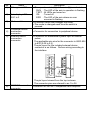
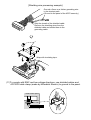
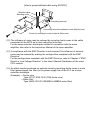
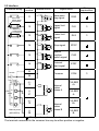
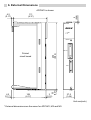
AD75M1/M2/M3 Positioning Module User’s Manual (Hardware) Thank you for buying the Mitsubishi general-purpose programmable logic controller MELSEC-A Series Prior to use, please read both this manual and detailed manual thoroughly and familiarize yourself with the product. MODEL AD75M-U-E(H/W) MODEL 13J885 CODE IB(NA)-66735-F(0409)MEE 1996 MITSUBISHI ELECTRIC CORPORATION ! SAFETY PRECAUTIONS ! (Always read before starting use) When using Mitsubishi equipment, thoroughly read this manual and the associated manuals introduced in this manual. Also pay careful attention to safety and handle the module properly. These precautions apply only to Mitsubishi equipment. Refer to using CPU module user's manual for a description of the PLC system safety precautions. These !SAFETY PRECAUTIONS! classify the safety precautions into two categories: "DANGER" and "CAUTION". DANGER Procedures which may lead to a dangerous condition and cause death or serious injury if not carried out properly. Procedures which may lead to a dangerous condition and CAUTION cause superficial to medium injury, or physical damage only, if not carried out properly. Depending on circumstances, procedures indicated by be linked to serious results. CAUTION may also In any case, it is important to follow the directions for usage. Store this manual in a safe place so that you can take it out and read it whenever necessary. Always forward it to the end user. [DESIGN PRECAUTIONS] DANGER ! Configure a safety circuit so that the safety of the overall system is maintained even when an external power error or PLC error occurs. An accident may occur by a false output or a malfunction. (1) Outside of the PLC, construct mechanical damage preventing interlock circuits such as emergency stop, positioning upper and lower limit switches. (2) During zero return operation, the module is controlled by two data: zero return direction and zero return speed, and speed begins to decelerate when the near point dog turns on. If the zero return direction is set incorrectly, the module may continue to operate without decelerating. To prevent damage to the module in such cases, configure an interlock circuit outside the PLC. CAUTION ! Do not bunch the control wires or communication cables with the main circuit or power wires, or install them close to each other. They should be installed 100 mm (3.9 inch) or more from each other. Not doing so could result in noise that would cause malfunction. [INSTALLATION PRECAUTIONS] CAUTION ! Use the PLC in an environment that meets the general specifications contained in this manual. Using this PLC in an environment outside the range of the general specifications could result in electric shook, fire, malfunction, and damage to or deterioration of the product. ! Insert the tabs at the bottom of the module into the mounting holes in the base module, and tighten the screws using the specified torque. If the module is not properly installed, it may result in malfunctions, failure, or fallout. ! Verify that the external device connector, SSCNET connector and RS-422 connector are securely attached to the connectors on the module. Confirm that they connect with an audible click. If not attached properly, a contact error may occur, resulting in incorrect input or output. ! Always attach a cover to connectors that are not used. If not covered, malfunctions may occur. ! Do not directly touch the module's conductive parts or electronic components. Doing so could cause malfunction or failure in the module. [WIRING PRECAUTIONS] CAUTION ! Be sure there are no foreign substances such as sawdust or wiring debris inside the module. Such debris could cause fires, failure, or malfunction. ! Perform soldering of the external device connector and SSCNET connector after verifying the pin layout. ! Perform soldering of those connectors correctly. False soldering may cause short circuits and malfunctions. [STARTUP AND MAINTENANCE PRECAUTIONS] DANGER ! Switch off all phases of the externally supplied power used in the system when cleaning the module. If you do not switch off the external power supply, it will cause malfunctions of the module. ! Do not disassemble or modify the modules. Doing so could cause failure, malfunction, injury, or fire. ! Make sure to switch all phases of the external power supply off before mounting or removing the module. If you do not switch off the external power supply, it will cause failure or malfunction of the module. ! Remove the external device connector and SSCNET connector after the system has been stopped. The system will stop if they are removed while the system is running. ! When performing test operation, set the parameter for the speed limit value to a slow setting and prepare for an immediate stop of the module should a dangerous condition occur during operation verification. ! Always make sure to touch the grounded metal to discharge the electricity charged in the body, etc., before touching the module. Failure to do so can cause the module to fail or malfunction. [USAGE PRECAUTIONS] CAUTION ! Exercise caution when the reference-axis speed for interpolation operation has been specified, since the speed of the opposite axis (second axis) can get greater than the set speed (speed limit value). [DISPOSAL PRECAUTIONS] CAUTION ! When disposing of this product, treat it as industrial waste. About the Manuals The following product are available for this equipment. Refer to the table given below to choose suitable manuals. Detailed Manual Manual name Positioning module type A1SD75M1/M2/M3, AD75M1/M2/M3 User's Manual Manual No. (Model code) IB-66715 (13J870) Related Manual Manual name Positioning module software package type SW1IVD-AD75P Operating Manual GX Configurator-AP Version 1 Operating Manual Manual No. (Model code) IB-66714 (13J915) IB-66900 (13J948) Correspondence to EMC DIRECTIVE For instructions to make the PLC compatible with EMC standards, refer to "EMC AND LOW-VOLTAGE DIRECTIVE" in PLC CPU User's Manual (Hardware). * When the PLC CPU user's manual (Hardware) does not include Chapter 3 "EMC AND LOW-VOLTAGE DIRECTIVE", refer to QnA Series CPU Compatible HighSpeed Accessing Basic Base Unit-Additional Explanation for Product Conforming to EMC Standards (IB-68837) (optional). 1. Overview This manual describes how to install AD75M1/M2/M3 Positioning Module (hereafter abbreviated as AD75) and how to wire them with external devices. After unpacking AD75, please confirm that the following products are contained. Product name AD75M1 Positioning Module AD75M2 Positioning Module AD75M3 Positioning Module Connector (10136-3000VE) External device connector (Model) Connector cover (10336-56F0-008) Quantity 1 1 1 1 2 3 1 2 3 2. Performance Specifications The performance specifications for the AD75 are shown below. Item Maximum output command speed Maximum connection distance between servos Number of occupied I/O points Internal current consumption Flash ROM write counts Access counts to the FeRAM when the absolute position detection system is employed External dimensions Weight Specifications 1Mpps Overall distance of SSCNET cable: 30m (98.43 ft.) 32 points 5VDC, 0.7A or less Max. 100,000 times Max. 9,999,900,000 times 250[9.84](H)×37.5[1.48](W)×106[4.17](D)[mm(inch)] 0.45kg 3. Names of Each Part The following shows the name of each part. AD75M1 AD75M2 AD75M3 1) AX1 AX1 AX2 MODE MODE RS-422 3) MODE RS-422 AX1 AX1 AX2 AX3 2) 4) RS-422 AX1 AX1 AX2 AX3 AX2 5) 5) FRONT FRONT SSCENT SSCENT FRONT SSCENT 6) AD75M1 front view AD75M2 front view AD75M3 front view No. 1) Name 17-segment LED 2) Axis display LEDs AX1 to 3 3) Mode switch 4) 5) Peripheral device connection connector External device connection connector Description • The operation state (1)) of the axis (2)) is indicated. RUN : The LED of the axis in operation is flashing TEST : All LEDs are turned on IDL : Turned off ERR : The LED of the axis where an error occurred is flashing • A selector switch that changes the mode. • The mode is changed each time the switch is pressed. • Connector for connection to peripheral device. • Connector for mechanical system input or manual pulsar. The applicable wire size for the connector is AWG #24 to #30 (0.05 to 0.2). The pin layout for the included external device connector is as follows. Perform wiring according to the interface. 2 20 19 1 Wire 18 35 36 17 Solder The pin layout viewed from the top is shown. The connector pins are referred to as 1 to 36. 6) SSCNET connection connector Connector for SSCNET-compatible servo amplifier 4. Loading and Installation The following is explanations of the handling precautions and installation environment which is common to modules when handling AD75 from unpacking to installation. For the details of loading and installation of the module, refer to User's Manual of PLC CPU module to be used. 4.1 Handling precautions (1) Because the case of the module is made of resin, be careful not to drop it or expose it to strong impact. (2) Do not remove the printed circuit board of the module from the case. This may cause malfunctions. (3) Be careful not to let foreign matters such as filings or wire chips get inside the module during wiring. When such matters do enter, be sure to remove them. (4) Execute tightening of the module's installation screws within the range indicated below. Screw position Module fixing screw (M4 screw) Tightening torque range 78 to 118 N•cm 4.2 Installation environment Do not install the A series PLC in the following environments. (1) Where the ambient temperature exceeds the 0 to 55°C range. (2) Where the ambient humidity exceeds the 10 to 90 % RH range. (3) Where condensation is produced by sudden temperature changes. (4) Where corrosive or combustible gas is present. (5) Where dust, iron powder and other conductive powder, oil mist, salt, or organic solvents are prevalent. (6) In direct sunlight. (7) Where a strong electric or magnetic field is generated. (8) Where vibration and shock may be transmitted directly to the module. 5. Wiring The wiring precautions for the AD75 are described below. 5.1 Precautions for wiring (1) Perform wiring of the AD75 correctly while checking the terminal arrangement. (2) Solder or crimp the external device connection connector correctly. An improperly soldered or crimped connector may cause malfunctions. (3) Be careful to avoid entry of chips, wiring dust and so on inside the AD75. Otherwise fire, failure or malfunction may be caused. (4) Be sure to install a cover for the external device connection connector if no external device is connected. Otherwise malfunction may be caused. (5) Connect the external device connection connector, SSCNET connection connector and peripheral device connection connector with the connector of the AD75. Check that the connector snaps. An improperly connected connector will cause poor continuity, possibly causing erroneous inputs or outputs. (6) Do not pull the cable when removing the cable from the AD75 or servo amplifier. Hold and pull the connector connected to the AD75 or servo amplifier. If the cable connected to the AD75 or servo amplifier is pulled, a malfunction may be caused. As well, the AD75, servo amplifier or cable may be broken. (7) Disconnect the external device connection connector and SSCNET connection connector when the system is stopped. If the external device connection connector or SSCNET connection connector is disconnected during operation of the system, the system will be stopped. (8) Route the cables connected to the AD75, in a duct, or fix them. If cables are not routed in the duct or no fixing measures are taken to them, drifting or moving cables, breakage of the AD75, servo amplifier or cable due to a carelessly pulled cable, or malfunction caused by a poorly connected cable may be caused. (9) Do not tie the AD75 cable with the main circuit cable, power cable, or a load cable for other than the programmable logic controller or do not route the AD75 cable near them. Separate these by 100 mm as a measure. Otherwise noise, surge or induction may cause a malfunction. (10) When routing the AD75 cable near a power cable at a distance smaller than 100 mm, use a shielded cable for a countermeasure against noise. Connect the shielding wire of the shielded cable securely to the panel of the AD75. [Shielding wire processing example] Ground a 2mm2 or a thicker grounding wire in the shortest path. (Ground to the panel of the AD75 securely.) Strip the sheath of the shielded cable. Remove the shielding wires from the shielded cable and solder them to the grounding cable. A Wrap with insulating tape. (11)To comply with EMC and low-voltage directives, use shielded cables and AD75CK cable clamp (made by Mitsubishi Electric) to ground to the panel. Inside control panel AD75 20 to 30cm AD75CK [How to ground shilded cable using AD75CK] Shielded cable Shielding wires Grounding terminal Grounding terminal installation screw (M4x8 screw) Screw for mounting to control cabinet (M4 screw) (12) The influence of noise may be reduced by mounting ferrite cores to the cable connected to the AD75 as a noise reduction technique. For the noise reduction techniques related to connection with the servo amplifier, also refer to the Instruction Manual of the servo amplifier. (13) If compliance with the EMC Directive is not required, the influence of external noise may be reduced by making the configuration compliant with the EMC Directive. For the configuration compliant with the EMC Directive, refer to Chapter 3 "EMC Directive, Low Voltage Directive" in the User's Manual (Hardware) of the used CPU module. (14) An effect may be produced on external noise by mounting ferrite cores or noise filter (power supply line filter) to the power supply line of the PLC as a noise reduction technique. (Example) " Ferrite core Type: ZCAT 3035-1330 (TDK ferrite core) " Noise filter Type: MXB-1210-33 (DENSEI-LAMBDA noise filter) 5.2 Interface External wiring When not using upper limit switch Pin number Signal name Wiring requirement 11 Near-point dog signal DOG 12 Upper limit signal FLS # 13 Lower limit signal RLS # 14 Stop signal STOP 15 Speed/ position switch signal CHG 16 External start signal STRT Common COM When not using lower limit switch 24VDC Internal circuit 35 36 5V 5VDC A (+) 9 (-) 27 Manual pulser phase A PULSER A+ PULSER A- B OV Manual pulser (MR-HDP01) (+) 10 (-) 28 Manual pulser phase B PULSER B+ PULSER B- : Wiring performed as required # : Wiring required The terminal connected to the common line may be either positive or negative. # 6. External Dimensions AD75M1 is shown. 111 (4.37) 2 (0.08) 4.2 (0.17) A D75M1 AX1 MODE RS-422 250 (9.84) Printed circuit board AX1 FRONT 4.2 (0.17) 106 (4.17) 5.3 (0.21) SSCENT 3 (0.12) 37.5 (1.48) Unit:mm(inch) * External dimensions are the same for AD75M1, M2 and M3. Warranty Mitsubishi will not be held liable for damage caused by factors found not to be the cause of Mitsubishi; machine damage or lost profits caused by faults in the Mitsubishi products; damage, secondary damage, accident compensation caused by special factors unpredictable by Mitsubishi; damages to products other than Mitsubishi products; and to other duties. For safe use " This product has been manufactured as a general-purpose part for general industries, and has not been designed or manufactured to be incorporated in a device or system used in purposes related to human life. " Before using the product for special purposes such as nuclear power, electric power, aerospace, medicine or passenger movement vehicles, consult with Mitsubishi. " This product has been manufactured under strict quality control. However, when installing the product where major accidents or losses could occur if the product fails, install appropriate backup or failsafe functions in the system. Country/Region Sales office/Tel U.S.A Mitsubishi Electric Automation Inc. 500 Corporate Woods Parkway Vernon Hills, IL 60061 Tel : +1-847-478-2100 Brazil MELCO-TEC Rep. Com.e Assessoria Tecnica Ltda. AV. Paulista 1471, Conj. 308, Sao Paulo City, Sao Paulo State, Brazil Tel : +55-11-283-2423 Germany Mitsubishi Electric Europe B.V. German Branch Gothaer Strasse 8 D-40880 Ratingen, GERMANY Tel : +49-2102-486-0 U.K Mitsubishi Electric Europe B.V. UK Branch Travellers Lane, Hatfield, Herts., AL10 8XB,UK Tel : +44-1707-276100 Italy Mitsubishi Electric Europe B.V. Italian Branch Centro Dir. Colleoni, Pal. Perseo-Ingr.2 Via Paracelso 12, 20041 Agrate B., Milano, Italy Tel : +39-039-6053344 Spain Mitsubishi Electric Europe B.V. Spanish Branch Carretera de Rubi 76-80 08190 - Sant Cugat del Valles, Barcelona, Spain Tel : +34-93-565-3131 France Mitsubishi Electric Europe B.V. French Branch 25 Boulevard des Bouvets, F-92741 Nanterre Cedex, France TEL: +33-1-5568-5568 South Africa Circuit Breaker Industries LTD. Tripswitch Drive, Elandsfontein Gauteng, South Africa Tel : +27-11-928-2000 Country/Region Sales office/Tel Hong Kong Ryoden Automation Ltd. 10th Floor, Manulife Tower, 169 Electric Road, North Point, HongKong Tel : +852-2887-8870 China Ryoden Automation Shanghai Ltd. 3F Block5 Building Automation Instrumentation Plaza 103 Cao Bao Rd. Shanghai 200233 China Tel : +86-21-6475-3228 Taiwan Setsuyo Enterprise Co., Ltd. 6F., No.105 Wu-Kung 3rd.RD, Wu-Ku Hsiang, Taipei Hsine, Taiwan Tel : +886-2-2299-2499 Korea HAN NEUNG TECHNO CO.,LTD. 1F Dong Seo Game Channel Bldg., 660-11, Deungchon-dong Kangsec-ku, Seoul, Korea Tel : +82-2-3660-9552 Singapore Mitsubishi Electric Asia Pte, Ltd. 307 ALEXANDRA ROAD #05-01/02, MITSUBISHI ELECTRIC BUILDING SINGAPORE 159943 Tel : +65-6473-2308 Thailand F. A. Tech Co.,Ltd. 898/28,29,30 S.V.City Building,Office Tower 2,Floor 17-18 Rama 3 Road, Bangkpongpang, Yannawa, Bangkok 10120 Tel : +66-2-682-6522 Indonesia P.T. Autoteknindo SUMBER MAKMUR Jl. Muara Karang Selatan Block A Utara No.1 Kav. No.11 Kawasan Industri/ Pergudangan Jakarta - Utara 14440 Tel : +62-21-663-0833 India Messung Systems Put,Ltd. Electronic Sadan NO:111 Unit No15, M.I.D.C BHOSARI,PUNE-411026 Tel : +91-20-712-2807 Australia Mitsubishi Electric Australia Pty. Ltd. 348 Victoria Road, PostalBag, No 2, Rydalmere, N.S.W 2116, Australia Tel : +61-2-9684-7777 HEAD OFFICE : 1-8-12, OFFICE TOWER Z 14F HARUMI CHUO-KU 104-6212, JAPAN NAGOYA WORKS : 1-14, YADA-MINAMI 5-CHOME, HIGASHI-KU, NAGOYA, JAPAN When exported from Japan, this manual does not require application to the Ministry of Economy, Trade and Industry for service transaction permission. Specifications subject to change without notice. Printed in Japan on recycled paper.