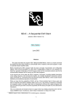
1
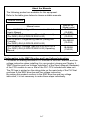
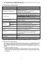
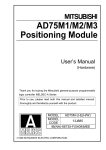
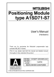
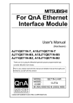
Intelligent Communication Module User’s Manual (Hardware) A1SD51S Thank you for buying the Mitsubishi general-purpose programmable logic controller MELSEC-A Series Prior to use, please read both this manual and detailed manual thoroughly and familiarize yourself with the product. MODEL A1SD51S-U-HW MODEL 13JP69 CODE IB(NA)-0800311-A(0509)MEE 2005 MITSUBISHI ELECTRIC CORPORATION z SAFETY PRECAUTIONS z (Always read these instructions before using this equipment.) Before using this product, please read this manual and the relevant manuals introduced in this manual carefully and pay full attention to safety to handle the product correctly. These precautions apply only to this product. For the PLC system safety precautions, refer to the user’s manual of your CPU module. In this manual, the safety instructions are ranked as "DANGER" and "CAUTION". DANGER Indicates that incorrect handling may cause hazardous conditions, resulting in death or severe injury. CAUTION Indicates that incorrect handling may cause hazardous conditions, resulting in medium or slight personal injury or physical damage. CAUTION level may lead to a serious consequence according Note that the to the circumstances. Always follow the instructions of both levels because they are important to personal safety. Please save this manual to make it accessible when required and always forward it to the end user. [DESIGN PRECAUTIONS] DANGER z Please refer to the manual for each data link concerning the operating status of each station when communications errors occur in the data link. There is danger of accidents due to wrong outputs or wrong operations. z When connecting a peripheral device to the CPU module or performing control of a PLC which is being run through a BASIC program, configure an interlock circuit in the sequence program so that the system overall is operating on the safe side at all times. Also, when performing other control (program modifications, changing the operating status (status control)) of a PLC that is currently running, read the manual thoroughly and proceed only after taking adequate safety precautions. Particularly in cases where the above control is performed toward PLC in remote locations from the opposite party's device, there may be occasions where it is impossible to respond immediately to trouble on the PLC side resulting from data communications errors. At the same time as you are configuring an interlock circuit in the sequence program, decide methods for the system to use to treat data communications errors between the opposite party's device and the PLC CPU. A-1 [DESIGN PRECAUTIONS] DANGER z Do not write data to the "System Area" in the intelligent function module's buffer memory. Also, do not turn the output for signals for "Use Prohibited" signals among the output signals from the PLC CPU to the intelligent function module (ON).If data are written to the "System Area" or output in response to "Use Prohibited" signals, there is danger that the PLC system will malfunction. CAUTION z Do not bunch the control wires or communication cables with the main circuit or power wires, or install them close to each other. They should be installed 100mm (3.94 in.) or more from each other. Not doing so could result in noise that may cause malfunction. z If a BASIC program is registered in the EEP-ROM in the module, do not perform a power OFF or PLC CPU reset operation at the station where the module is installed during registration. If a power OFF or PLC CPU reset operation is performed at the station where the module is installed during registration, the data contents in the EEP-ROM will be indefinite and it will be necessary to reset the setting values, etc. in the buffer memory and register them again in the EEP-ROM. It could also cause the module to break down or malfunction. [INSTALLATION PRECAUTIONS] CAUTION z Use the PLC in an environment that meets the general specifications contained in the user's manual of the CPU moudle to use. Using this PLC in an environment outside the range of the general specifications may cause electric shock, fire, malfunction, and damage to or deterioration of the product. z Insert the module fixing projection into the fixing hole in the base unit to press the module using the hole as the fulcrum, and then tighten the fixing screw with the specified torque. When no screw is tightened, even if the module is installed correctly, it may cause malfunctions, a failure or a drop of the module. z Tighten the screws within the range of specified torque. If the screws are loose, it may cause the module to fallout, short circuits, or malfunction. If the screws are tightened too much, it may cause damage to the screw and/or the module, resulting in fall out, short circuits or malfunction. z Shut off all phases of the external power supply in the system before mounting or dismounting the module. Failure to do so may damage the product. z Do not directly touch the conductive area or electronic components of the module. Doing so may cause malfunction or failure in the module. A-2 [WIRING PRECAUTIONS] CAUTION z If the module is turned on and operated after installation or wiring operations, etc., be sure install the terminal cover provided with this product. If the terminal cover is not installed, there is danger of malfunction. z When connecting wires to the connector used for external connections, be sure to crimp, pressure weld or solder the wires correctly using the tool specified by the manufacturer. If connections are not perfect, it could result in short circuits, fire or malfunction. z Securely insatll the connector to the module. z Be sure to fix communication cables leading from the module by placing them in the duct or clamping them. Cables not placed in the duct or without clamping may hang or shift, allowing them to be accidentally pulled, which may cause a module malfunction and cable damage. z When connecting cables, be sure to do so correctly after confirming the type of interface you are connecting to. If connection is made to a different interface or if wiring is faulty, it could cause the module or external device to break down. z Tighten the terminal screws within the range of specified torque. If the terminal screws are loose, it may result in short circuits or malfunction. If the screws are tightened too much, it may cause damage to the screw and/or the module, resulting in the module falling out, short circuits or malfunction. z When disconnecting the communications cable or power cable that is connected to the module, do not disconnect it by grasping the cable with your hand and pulling it. Disconnect cables with connectors attached by taking hold of the connector at the connection with the module and pulling the connector. For cables connected to a terminal block, remove the cable after loosening the terminal block screws. If the cable is pulled while it is connected to the module, it could cause malfunction or damage the module or the cable. z Be careful not to let foreign objects such as swarf or wire chips get inside the module. They may cause fires, failure or malfunction. A-3 [STARTING AND MAINTENANCE PRECAUTIONS] CAUTION z Do not disassemble or modify the each module. Doing so could cause failure, malfunction injury or fire. z Shut off all phases of the external power supply in the system before mounting or dismounting the module. Failure to do so may cause failure or malfunction of the module. z Do not touch the connector while the power is on. Doing so may cause malfunction. z Shut off all phases of the external power supply in the system before cleaning or retightening the terminal screws or module fixing screws. Not doing so may cause failure or malfunction of the module. If the screws are loose, it may cause the module to fallout, short circuits, or malfunction. If the screws are tightened too much, it may cause damages to the screws and or/the module, resulting in fall out, short circuits or malfunction. z Always make sure to touch the grounded metal to discharge the electricity charged in the body, etc., before touching the module. Failure to do so may cause a failure or malfunctions of the module. [OPERATING PRECAUTIONS] CAUTION z When performing control (in particular, changing data, changing a program or changing the operation status (status control)) of the PLC during operation using a BASIC program, do so only after reading the user's manual thoroughly and taking adequate safety precautions. If there are errors when changing data, changing a program or in status control, it could result in system malfunction, or cause mechanical damage or accidents. [DISPOSAL PRECAUTIONS] CAUTION z When disposing of this product, treat it as industrial waste. A-4 Revisions Print Date Sep., 2005 The manual number is noted at the lower right of the top cover. *Manual Number Revision IB(NA)-0800311-A First printing This manual confers no industrial property rights or any rights of any other kind, nor does it confer any patent licenses. Mitsubishi electric Corporation cannot be held responsible for any problems involving industrial property rights which may occur as a result of using the contents noted in this manual. 2005 MITSUBISHI ELECTRIC CORPORATION A-5 CONTENTS 1. Overview ........................................................................................................1 2. Performance Specifications............................................................................2 2.1 Performance Specifications ......................................................................2 2.2 Connector Specifications ..........................................................................4 2.2.1 RS-232C interface (CH1/CH2) .........................................................4 2.2.2 RS-422/485 interface (CH3).............................................................5 3. Loading and Installation .................................................................................6 3.1 Precautions for handling ...........................................................................6 3.2 Installation conditions ...............................................................................6 4. External Wiring...............................................................................................7 4.1 RS-232C Connection................................................................................7 4.2 RS-422/485 Connection ...........................................................................8 5. Part Names And Setting.................................................................................9 6. External Dimensions ....................................................................................15 A-6 About the Manuals The following product are available for this equipment. Refer to the table given below to choose suitable manuals. Related Manual Manual name Type A1SD51S Intelligent Communication Module User’s Manual AD51H-BASIC Programming Manual (Command) (For QD51(-R24),A1SD51S,AD51H-S3) AD51H-BASIC Programming Manual (Debag and Compile) (For QD51(-R24),A1SD51S,AD51H-S3) AD51H-BASIC Package Type SW1IVD-AD51HP-E (For QD51(-R24),A1SD51S,AD51H-S3) Operating Manual Manual No. (Model code) IB-66551 (13JE90) SH-080090 (13JF63) SH-080091 (13JF64) IB-66698 (13J910) Conformation to the EMC Directive and Low Voltage Instruction For details on making Mitsubishi PLC conform to the EMC directive and low voltage instruction when installing it in your product, please see Chapter 3, "EMC Directive and Low Voltage Instruction" of the User's Manual (Hardware) of the CPU module to use or that of the PLC CPU included with base unit. The CE logo is printed on the rating plate on the main body of the PLC that conforms to the EMC directive and low voltage instruction. By making this product conform to the EMC directive and low voltage instruction, it is not necessary to make those steps individually. A-7 1. Overview This manual explains the specifications and part names of the A1SD51S intelligent communication module that is used in combination with the MELSEC-A series compact building block type PLC CPU. After unpacking, make sure that the following is included. Model A1SD51S Product name A1SD51S intelligent communication module 1 Quantity 1 2. Performance Specifications 2.1 Performance Specifications Item Programming language Number of tasks Conditions for starting tasks Internal memory General-purpose I/O Buffer Built-in interfaces RS-422/485 I/F RS-232C I/F Memory backup Writing a user program to the ROM Console Number of occupied I/O points 5V DC Internal current consumption External dimensions Weight Specification • AD51H-BASIC • Max. two tasks • Started by power ON • Started by an interrupt from the PC CPU (Not started in Compile BASIC) • Started by the start command from another task • Program memory: Max. 64 K bytes/two takes (Tasks size can be set to 16K, 32K, 48K or 64K bytes) • Common memory: 8 K bytes • Expansion register: 1024 points (2 K bytes) • Expansion relay: 1024 points • Input: 27 points • Output: 23 points • 3 K words (6 K bytes) • Conforms to RS-422 Channel 3 Used with a connector Transmission distance: within 500m • Conforms to RS-232C Channels 1 and 2 Used with a connector Transmission distance: within 15m • Backup capability provide (common memory, extension relay, extension register) *1 • Disabled (However, a built-in EEP-ROM is installed in the body of the A1SD51S.) *2 • PC/AT • VG-620 (manufactured by Victor Data Systems) • VT-382 (manufactured by the Japan Digital Equipment Inc.) • 32 points • 0.4A • 130 (5.12)(H) 34 (1.39)(W) • 0.3 kg (0.66 lb) 93.6 (3.69)(D) [mm(in.)] For general specifications, refer to the user’s manual of your CPU module. *1 Precautions for data backup When data is backed up using the common memory, extended register (ED) and extended relay (EM), be careful for the following points. When data is cleared at the A1SD51S start-up (SW9 is ON), the installation position is not limited. (1) Module installation position Install A1SD51S at the final slot of the main base or the extension base. (Make sure that the right side of A1SD51S has no module or blank cover (A1SG60).) 2 Note A1SD51S uses the super-capacitor (capacitor) for backup. When the super-capacitor is used at a high temperature, the backup time becomes short. To reduce the temperature of the super-capacitor, be sure to observe the installation position. The super-capacitor has a life span. When exceeding its life span, replace the super-capacitor. (2) Backup time MIN. 48 hours (assurance value) TYP. 120 hours (practical value) (3) Other items (a) If backup exceeding the backup time is required, backup the data with the PLC CPU. (A program that transfers data with the PLC CPU is required.) (b) The charging time of the super-capacitor is one hour. (When the charging time is less than 1 hour, the backup time is short.) (c) The life of the super-capacitor is shown in the diagram below. When the super-capacitor exceeds the service life (total power supply time) below, replace the super-capacitor. (When replacing a super-capacitor, please consult your local Mitsubishi service or representative. When requesting replacement, store the data of the common memory, extended register (ED) and extended relay (EM).) Total power supply time (hr) 150,000 100,000 88,000 50,000 31,000 10 20 30 40 50 55 Ambient temparature ( C) Life of super-capacitor *2 The EEP-ROM can be rewritten 10000 times. Rewriting is performed with the following system commands: y MSAVE y SET 3 2.2 Connector Specifications 2.2.1 RS-232C interface (CH1/CH2) Item Debugger port Applicable Console port device General -purpose port Transmission method Synchronization method Transmission speed Parity bit Transmission Stop bit specification Character data settings bit Communication control Model Specification VG-620, VT-382, PC/AT (Console port is CH1 only.) External devices with the RS-232C interface Conforms to RS-232C Asynchronous system Selectable from 300, 600, 1200, 2400, 4800, 9600 and 19200bps Yes or no (odd parity/even parity) 1, 1.5, 2 bits 5, 6, 7, 8 bits DTR/DSR(ER/DR) control or DC code control 17JE-13090-02(D8A) manufactured by DDK End view of connector Pin Connector of arrangement the A1SD51S and pin numbers Selectable 9 8 7 6 5 4 3 2 1 Pin No. Signal abbreviation 2 3 RD(RXD) SD(TXD) 4 ER(DTR) 5 6 SG DR(DSR) 7 RS(RTS) 8 CS(CTS) 4 Signal name Receive data Send data Data terminal ready Signal ground Dataset ready Request to send Clear to send Signal direction A1SD51S External device 2.2.2 RS-422/485 interface (CH3) Item Debugger port Applicable Console port device General -purpose port Transmission method Synchronization method Transmission speed Parity bit Transmission Stop bit specification Character data settings bit Communication control Model Specification PC/AT External devices with the RS-422/485 interface Conforms to RS-422 Asynchronous system Selectable from 300, 600, 1200, 2400, 4800, 9600 and 19200bps Yes or no (odd parity/even parity) 1, 1.5, 2 bits 5, 6, 7, 8 bits CS(CTS) control 17L-10250-27-D9A manufactured by DDK End view of connector Pin Connector of arrangement the A1SD51S and pin numbers Selectable 25 24 23 22 21 20 19 18 17 16 15 14 13 12 11 10 9 8 7 6 5 4 3 2 1 Pin No. Signal abbreviation 2 RDA 15 RDB 3 SDA 16 SDB 4 RSA 17 RSB 5 CSA 18 CSB 20 SG Signal name Signal direction A1SD51S External device Receive data Send data Request to send Clear to send Signal ground 21 RR *1 Receive ready *1: To enable data reception by the A1SD51S, be sure to connect RR (receive ready) to both the SG (No.20 pin) of the A1SD51S and the SG of the external device as shown above. Note (1) Function block diagram (+) 300 110 (-) (+) 300 110 Senc data Receive data (-) 5 3. Loading and Installation 3.1 Precautions for handling (1) Since the module case is made of resin, do not drop it or subject it to shock. (2) Do not remove the PC board from the module case. This may cause a fault. (3) Take precautions to prevent wire scraps or foreign material from falling into the top of the module. (4) Tighten the module mounting screws (usually unnecessary) with a torque in the following range: Screw Tightening Torque Range Module mounting screw (usually unnecessary) 78 to 118Nycm (M4 0.7 screw) (5) Load the module to the base with its hooks completely engaged with the base. To remove the module, first disengage the hooks from the base, then pull the module toward you. (For details, refer to the user’s manual for a small building block type CPU.) 3.2 Installation conditions Do not install the A1SD51S in the following locations. (1) Locations where the ambient temperature is outside the range 0 to 55 . (2) Locations where the ambient humidity is outside the range 10% RH to 90% RH. (3) Locations where dewing occurs due to sudden temperature changes. (4) Locations exposed to corrosive or combustible gases. (5) Locations exposed to large amounts of highly conductive dust, iron powder, oil mist, salt or organic solvents. (6) Locations where the module is exposed to direct sunlight. (7) Locations where a strong electric or magnetic field is generated. (8) Locations where the module will be subject to direct vibration or impact. 6 4. External Wiring 4.1 RS-232C Connection The standard method for the RS-232C cable connection is indicated below. For details on the connection method, refer to the user’s manual of the A1SD51S intelligent communication module. (1) External wiring example for DTR/DSR (ER/DR) control or DC code control A1SD51S External Device Cable Connection and Signal Direction (Connection Example) Signal Pin No. Signal RD(RXD) 2 RD(RXD) SD(TXD) 3 SD(TXD) ER(DTR) 4 ER(DTR) SG 5 SG DR(DSR) 6 DR(DSR) RS(RTS) 7 RS(RTS) CS(CTS) CS(CTS) 8 For this wiring, enable the DC code control or DTR/DSR (ER/DR) control with Processing Code 18 of the ZCNTL command. (2) External wiring example for DC code control A1SD51S External Device Cable Connection and Signal Direction (Connection Example) Signal Pin No. Signal RD(RXD) 2 RD(RXD) SD(TXD) 3 SD(TXD) ER(DTR) 4 ER(DTR) SG 5 SG DR(DSR) 6 DR(DSR) RS(RTS) 7 RS(RTS) CS(CTS) CS(CTS) 8 For this wiring, enable the DC code control with Processing Code 18 of the ZCNTL command. 7 4.2 RS-422/485 Connection The standard method for one-to-one (1:1) connection of the RS-422/485 cable is indicated below. A1SD51S External Device Cable Connection and Signal Direction (Connection Example) Signal Pin No. Signal SDA 3 RDA SDB 16 RDB RDA 2 SDA RDB 15 SDB CSA 5 RSA CSB 18 RSB RSA 4 CSA RSB 17 CSB RR 21 SG SG 20 For the terminating resistor setting and an external wiring example for multi-drop (1:n) connection, refer to the user’s manual of the A1SD51S intelligent communication module. 8 5. Part Names And Setting A1SD51S RUN S. ERR PROG MTSE P1. RUN P1. ERR P2. RUN P2. ERR CH1 CH1 CH2 CH2 CH3 CH3 SD RD SD RD SD RD 1) M. PRO. MODE 9 678 A BCD RUN STOP RESET 01 EF 2 345 3) CH1(RS-232-C) 5) SW 1 2 3 4 5 6 7 8 2) 4) 9 10 11 12 CH2(RS-232-C) 6) FRONT SIDE CH3 RS- RS422 485 8) No. Name (1) LED RUN S. ERR PROG MTSE P1. RUN P1. ERR P2. RUN P2. ERR CH1 CH1 CH2 CH2 CH3 CH3 RUN SD RD SD RD SD RD M. PRO. S.ERR PROG MTSE P1.RUN P1.ERR P2.RUN P2.ERR CH1 SD CH1 RD CH2 SD CH2 RD CH3 SD CH3 RD M.PRO. 7) Description Normal operation Normal: ON Error: OFF System error Normal: OFF Error: ON Programming mode In programming mode: ON Multitask setting error Setting error occurred: ON Task 1 execution Task 1 being executed: ON Task 1 error Error occurred in task 1: ON Task 2 execution Task 2 being executed: ON Task 2 error Error occurred in task 2: ON CH1 send status Data being sent: Flashing CH1 receive status Data being received: Flashing CH2 send status Data being sent: Flashing CH2 receive status Data being received: Flashing CH3 send status Data being sent: Flashing CH3 receive status Data being received: Flashing Memory protect status Memory protected (when SW10 is ON): ON 9 No. Name (2) RUN switch RUN STOP RESET (3) Mode setting switch 1 MODE 9 678 A 01 EF 2 BCD 345 (4) Mode setting switch 2 1 2 3 4 5 6 7 8 9 10 11 12 Description Used to execute/stop tasks or to reset the hardware. yRUN : Executes tasks. (Enabled only in execution/debugging mode) ySTOP : Stops tasks. (Enabled only in execution/debugging mode) yRESET : Resets the hardware. Mode setting (Factory setting: 0) Mode Description 0 Execution mode 1 2 Multitask debugging mode 3 4 Programming mode 5 to F Use not allowed Consol and other settings Status SW Setting ON OFF 1 2 Console/Debugger port Refer to *1 3 setting 4 5 BASIC program stop by 6 pressing [Break] key or Enabled Disabled [Ctrl] + [C] keys 7 PLC CPU reset Enabled Disabled Accessible time after PLC 8 2000ms 200ms CPU reset Cleared at 9 Backup area clear Not cleared startup EEP-ROM write protect Not 10 Protected setting protected 11 Not used 12 10 *1 Consol/debugger port setting (1) When connecting console to CH3 Console The following is connected to CH3: y PC/AT Debugger Not connected Setting SW1 SW2 SW3 SW4 SW5 ON The following is connected to CH1: y VT-382 y PC/AT SW1 SW2 SW3 SW4 SW5 ON The following is connected to CH1: y VG-620 SW1 SW2 SW3 SW4 SW5 ON The following is connected to CH2: y VT-382 y PC/AT SW1 SW2 SW3 SW4 SW5 ON The following is connected to CH2: y VG-620 SW1 SW2 SW3 SW4 SW5 ON 11 (2) When connecting console to CH1 Consol The following is connected to CH1: y VT-382 y PC/AT Debugger Not connected Setting SW1 SW2 SW3 SW4 SW5 ON The following is connected to CH3: y PC/AT SW1 SW2 SW3 SW4 SW5 ON The following is connected to CH2: y VT-382 y PC/AT SW1 SW2 SW3 SW4 SW5 ON The following is connected to CH1: y VG-620 Not connected SW1 SW2 SW3 SW4 SW5 ON The following is connected to CH3: y PC/AT SW1 SW2 SW3 SW4 SW5 ON The following is connected to CH2: y VG-620 SW1 SW2 SW3 SW4 SW5 ON 12 (3) When connecting no console Console Not connected Debugger Not connected Setting SW1 SW2 SW3 SW4 SW5 ON The following is connected to CH3: y PC/AT SW1 SW2 SW3 SW4 SW5 ON The following is connected to CH1: y VT-382 y PC/AT SW1 SW2 SW3 SW4 SW5 ON The following is connected to CH1: y VG-620 SW1 SW2 SW3 SW4 SW5 ON The following is connected to CH2: y VT-382 y PC/AT SW1 SW2 SW3 SW4 SW5 ON The following is connected to CH2: y VG-620 SW1 SW2 SW3 SW4 SW5 ON 13 No. (5) (6) (7) (8) Name RS-232C interface (CH1) RS-232C interface (CH2) RS-422 interface (CH3) Terminating resistor selector switch Description y A console, debugger or external device, etc. is connected to this. y A debugger or external device, etc. is connected to this. y A console, debugger or external device, etc. is connected to this. y Terminating resistor setting for RS-422/485 is selected. RS-422 : 330 Neutral : Not connected RS-485 : 110 14 6. External Dimensions A1SD51S RUN S. ERR PROG MTSE P1. RUN P1. ERR P2. RUN P2. ERR CH1 CH1 CH2 CH2 CH3 CH3 SD RD SD RD SD RD M. PRO. MODE RUN STOP RESET 01 EF 2 89 67 A BCD 345 130 (5.12) CH1(RS-232-C) SW 1 2 3 4 5 6 7 8 9 10 11 12 CH2(RS-232-C) FRONT SIDE CH3 RS- RS422 485 6.5 (0.26) 93.6 (3.69) 34 (1.39) Unit:mm (inch) 15 Warranty Mitsubishi will not be held liable for damage caused by factors found not to be the cause of Mitsubishi; machine damage or lost profits caused by faults in the Mitsubishi products; damage, secondary damage, accident compensation caused by special factors unpredictable by Mitsubishi; damages to products other than Mitsubishi products; and to other duties. For safe use y This product has been manufactured as a general-purpose part for general industries, and has not been designed or manufactured to be incorporated in a device or system used in purposes related to human life. y Before using the product for special purposes such as nuclear power, electric power, aerospace, medicine or passenger movement vehicles, consult with Mitsubishi. y This product has been manufactured under strict quality control. However, when installing the product where major accidents or losses could occur if the product fails, install appropriate backup or failsafe functions in the system. Country/Region Sales office/Tel U.S.A Mitsubishi Electric Automation Inc. 500 Corporate Woods Parkway Vernon Hills, IL 60061 Tel : +1-847-478-2100 Brazil MELCO-TEC Rep. Com.e Assessoria Tecnica Ltda. Rua Correia Dias, 184, Edificio Paraiso Trade Center-8 andar Paraiso, Sao Paulo, SP Brazil Tel : +55-11-5908-8331 Germany Mitsubishi Electric Europe B.V. German Branch Gothaer Strasse 8 D-40880 Ratingen, GERMANY Tel : +49-2102-486-0 U.K Mitsubishi Electric Europe B.V. UK Branch Travellers Lane, Hatfield, Herts., AL10 8XB,UK Tel : +44-1707-276100 Italy Mitsubishi Electric Europe B.V. Italian Branch Centro Dir. Colleoni, Pal. Perseo-Ingr.2 Via Paracelso 12, 20041 Agrate B., Milano, Italy Tel : +39-039-6053344 Spain Mitsubishi Electric Europe B.V. Spanish Branch Carretera de Rubi 76-80 08190 Sant Cugat del Valles, Barcelona, Spain Tel : +34-93-565-3131 France Mitsubishi Electric Europe B.V. French Branch 25 Boulevard des Bouvets, F-92741 Nanterre Cedex, France TEL: +33-1-5568-5568 South Africa Circuit Breaker Industries LTD. Tripswitch Drive, Elandsfontein Gauteng, South Africa Tel : +27-11-928-2000 Country/Region Sales office/Tel Hong Kong Ryoden Automation Ltd. 10th Floor, Manulife Tower, 169 Electric Road, North Point, HongKong Tel : +852-2887-8870 China Ryoden Automation Shanghai Ltd. 3F Block5 Building Automation Instrumentation Plaza 103 Cao Bao Rd. Shanghai 200233 China Tel : +86-21-6120-0808 Taiwan Setsuyo Enterprise Co., Ltd. 6F., No.105 Wu-Kung 3rd.RD, Wu-Ku Hsiang, Taipei Hsine, Taiwan Tel : +886-2-2299-2499 Korea HAN NEUNG TECHNO CO.,LTD. 1F Dong Seo Game Channel Bldg., 660-11, Deungchon-dong Kangsec-ku, Seoul, Korea Tel : +82-2-3660-9552 Singapore Mitsubishi Electric Asia Pte, Ltd. 307 Alexandra Road #05-01/02, Mitsubishi Electric Building Singapore 159943 Tel : +65-6473-2308 Thailand F. A. Tech Co.,Ltd. 898/28,29,30 S.V.City Building,Office Tower 2,Floor 17-18 Rama 3 Road, Bangkpongpang, Yannawa, Bangkok 10120 Tel : +66-2-682-6522 Indonesia P.T. Autoteknindo SUMBER MAKMUR Jl. Muara Karang Selatan Block a Utara No.1 Kav. No.11 Kawasan Industri/ Pergudangan Jakarta - Utara 14440 Tel : +62-21-663-0833 India Messung Systems Put,Ltd. Electronic Sadan NO:111 Unit No15, M.I.D.C BHOSARI,PUNE-411026, India Tel : +91-20-712-2807 Australia Mitsubishi Electric Australia Pty. Ltd. 348 Victoria Road, PostalBag, No 2, Rydalmere, N.S.W 2116, Australia Tel : +61-2-9684-7777 HEAD OFFICE : 1-8-12, OFFICE TOWER Z 14F HARUMI CHUO-KU 104-6212, JAPAN NAGOYA WORKS : 1-14, YADA-MINAMI 5-CHOME, HIGASHI-KU, NAGOYA, JAPAN When exported from Japan, this manual does not require application to the Ministry of Economy, Trade and Industry for service transaction permission. Specifications subject to change without notice. Printed in Japan on recycled paper.