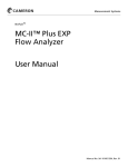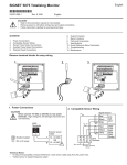
1
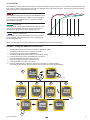
English
Signet 8150 Flow Totalizer
*3-8150.090-1*
Rev. E 2/06 English
3-8150.090-1
1.
2.
3.
4.
5.
6.
7.
8.
9.
Topic:
Description
Specifications
Installation
Wiring
Battery Installation and Replacement
Operation
Security Code
Totalizer operation
Automatic Calibration
Page
1
1
2
4
4
5
6
7
9
10.
11.
12.
13.
14.
15.
16.
17.
18.
19.
Topic:
Flow K-factor
Total K-factor
Time Base
Decimal point placement
Speed
Sensitivity
Troubleshooting
Flow and Totalizer K-factor selection
K-factor Charts
Ordering Information
Page
10
11
12
13
14
15
16
16
17
20
1. Description
The Signet 8150 Flow Totalizer is a battery-powered instrument capable of providing uninterrupted flow and total volume information for
4 years and beyond. The unique features of the 8150 include:
• Easy setup and display selection with 4-button keypad
• User selectable security access to prevent unwanted programming changes.
• Displays flow rate from 0.001 to 9999 engineering units with an auto-ranging decimal point.
• Three totalizers, one permanent and two that are independently resettable.
• Displays elapsed time between operating periods.
• Integral mount and panel mount options
• 3.6 V Lithium batteries last 4 years nominal in most applications.
• Non-volatile memory stores all programming and totalizer values even when batteries are removed.
Dimensions
Optional
Rear
Cover
41 mm
56 mm
92 mm
96 mm
(3.8 in.)
96 mm
42 mm
(1.7 in.)
96 mm
97 mm
106 mm
102 mm (4.0 in.)
SIDE VIEW
Panel Mount
60 mm
(2.3 in.)
82 mm
Front View
Integral Mount
Universal Mount
2. Specifications
General
Compatibility:
Input Frequency Range:
Accuracy:
Enclosure:
•
Rating:
•
Dimensions:
•
•
Case material:
Keypad material:
Signet 515, 525, 2517 Flow Sensors
1 to 400 Hz
±0.5% of reading
NEMA 4X/IP65 (front panel)
1/4 DIN
(96 x 96 x 50 mm)
(3.8 x 3.8 x 2.0 in.)
PBT resin
Sealed 4-key silicon rubber
Display: LCD type
• 4-digit upper line: flow rate
• 8-digit lower line: Three totalizer options:
Permanent Totalizer for life of instrument
Totalizer 1: resettable from keypad or remote 30 m (100 ft)
Totalizer 2: resettable with security code only
• Display Contrast: Automatic
Electrical:
•
Battery:
•
•
•
Two 3.6V Lithium thionyl chloride,
AA-size
Sensor power output: +3.6 VDC @ 20µA
Battery life:
4 years nominal @ 50°C (122°F)
Low Battery indication: Battery symbol on LCD display
Environmental:
•
Operating Temperature: -10°C to 65°C (14°F to 149°F)
•
Storage Temperature: -40 to 100°C (-40 to 212°F)
•
Relative Humidity:
0 to 95% Non-condensing
Shipping Weight:
0.5 kg (1.1 lbs.)
Quality Standards:
•
CE, CUL, UL
•
EN 61326: 2002 Class B
•
Manufactured under ISO 9001:2000 for Quality and ISO
14001:2004 for Environmental Management
3. Installation
3.1 Integral Installation with Field Mount Totalizer
3.2 Remote Field mount on wall
Flow
Totalizer
(3-8150-1)
The parts identified in Bold type are required for this installation.
Other parts are shown for reference only.
Use 2-conductor shielded cable no more than 30 m (100 ft.) long.
Integral
adapter Kit
(3-8051)
Integral Mount
3-8150-PO
3-8150-P1
3-8150-TO
3-8150-VO
Universal
Conduit Base
(3-8050)
Flow
Totalizer
(3-8150-1)
Integral
Flow Sensor
(3-8510-XX)
Terminal Cover
(4-3111)
Signet
Fittings
3.3 Plastic sensor installation tips
•
•
•
Lubricate the sensor O-rings with a suitable lubricant.
Do not use any petroleum based lubricant that will attack the
O-rings.
Using an alternating/twisting motion, lower the sensor into
the fitting, making sure the installation arrows on the black
cap are pointing in the direction of
flow.
sensor
black
bale
Engage one thread of the sensor
conduit
cap
cap then turn the sensor until the
tab
alignment tab is seated in the fitting
notch. Hand tighten the sensor cap.
notch
DO NOT use any tools on the sensor
cap or the cap threads and/or fitting
flange threads will be damaged.
Liquid-tight Connector
(3-9000.392-1)
Integral
Adapter kit
(3-8051)
Integral
Flow Sensor
(3-8510)
sensor
cap
Signet
Fittings
3.4 Conduit base Assembly Detail
1.
Insert the wires from the sensor through the yellow conduit
base and locking ring.
2.
Insert the locking ring into the conduit base, aligning it so that
the square tab is close to the conduit ports.
3.
Insert the mounting screw into the conduit base so the
head of the screw presses down on the locking ring when
tightened.
4.
Connect sensor wires to the terminal connections on the
integral totalizer or terminal cover.
5.
For remote assembly, connect output wires to terminal cover
output.
3-8150
Flow Totalizer
Mounting
Screw
Do not use this hole.
Square Tab
6.
Route the output wires through the conduit port in the conduit
base. Use a liquid-tight connector or conduit connector to
prevent moisture from entering the assembly.
7.
Place totalizer or cover onto conduit base and twist to lock in
place.
Locking
Ring
Conduit
Base
Kit
The Mounting Screw for the
Locking Ring goes into the Conduit
Base (not the Locking Ring) -- the
screw head rests on the lip of the
Locking Ring
5
Conduit
Base
Conduit
Ports
Sensor wires
2
8150 Flow Totalizer
3.5 Remote Field mount on pipe
3.6 Remote Installation with Panel mount totalizer
The parts identified in Bold type are required for this installation.
Other parts are shown for reference only.
The parts identified in Bold type are required for this installation.
Other parts are shown for reference only.
Use 2-conductor shielded cable no more than 30 m (100 ft.) long.
Totalizer
Panel Mount
(3-8150-1P)
Signet Total Flow
ENTER
Flow
Totalizer
(3-8150-1)
Standard Mount
Paddlewheel
(P51530)
Standard Mount
Paddlewheel
(P51530)
Signet
Fittings
Universal
Mounting Kit
(3-8050)
Signet
Fittings
3.7 Panel Mount Installation Detail
•
•
The 8150-1P Panel-mount Totalizer is a standard ¼ DIN package. Use a 92x92 mm punch tool to make the panel cutout.
Minimum spacing of 25 mm (1 in.) between panel units is recommended.
panel
gasket
terminals
latch
7
92 x 9
(3.62 2 mm
x 3.62
in.)
2
1
Pwr
System
Loop
Pwr
System
+
Loop
4
3
Outpu
t-
6
5
Outpu
mounting
bracket
d
sr Gn
SenIEL
D)
(SH
sr IN
SenD)
(RE
sr V+
SenAC
K)
(BL
t+
Panel Mount
Installation Detail
Panel cutout
8150 Flow Totalizer
quick-clips
3
4. Wiring
•
•
•
•
•
The wiring is identical for the panel mount and the field mount versions of the totalizer.
Only one wire should be inserted into a terminal. Splice double wires outside the terminal.
External Reset for Total #1: Use no more than 30 m (100 ft.) of 2-conductor twisted-pair cable connected to a dry contact (for
example, an ordinary door-bell button or relay contact).
Only Totalizer #1 can be be reset by the external connection.
Total #1 will not be displayed unless it is the standard totalizer selection.
10 mm
Instructions
1. Remove 10mm (3/8 in.) of insulation from sensor cable conductors.
2. Press down on orange lever to open terminal.
3. Insert wire into terminal until it hits bottom.
4. Release the lever to secure wire.
Splice BLK and SHLD
together outside of terminal
Sine wave Input Wiring
Use this wiring scheme for
Signet models 515, 525 and 2517.
+
#1
-
BLACK
+
#2
1
2
3
4
5
6
RED
Connect shield
to Ground wire
SH
IE
LD
525
2517
515
Totalizer 1
Remote reset
Terminal no.
1
2
3
4
5
6
Function
Signal Ground
Sensor signal
Open Collector Signal
DC Power to sensor
Ground
Ext. Reset
5. Battery Installation and Replacement
Two 3.6V Lithium thionyl chloride batteries, AA-size (7400-0011) are included with the totalizer.
NOTE: THE 8150 WILL NOT OPERATE WITH STANDARD 1.5 V ALKALINE BATTERIES. USE 3.6 V LITHIUM BATTERIES ONLY!
•
•
•
•
•
Observe polarity! Note that both batteries should face the
same direction.
When the “low battery” indicator appears on the display, both
batteries should be replaced within 90 days.
Remove and replace battery #1 first, then remove and
replace battery #2.
This ensures that all settings and totalizer values are saved.
If the low battery symbol reappears for more than 10
seconds after installing new batteries, one battery is
reversed, or battery #2 was installed before battery #1.
Secure the batteries by fastening the Velcro® straps.
CAUTION
When replacing batteries,
remove and replace
one battery at a time
Signet Total Flow
ENTER
Remove and replace
this battery first.
+
+
-
-
1
2
3
4
5
6
Note: Lithium Batteries
Dispose of properly!
Replace with 3.6 V Lithium battery
DISPOSE OF EXPENDED BATTERIES PROPERLY!
Lithium batteries contain hazardous chemicals. Dispose of
batteries according to local regulation.
4
8150 Flow Totalizer
6. Operation
The 8150-1 display shows the flow rate in large numerals and
a totalizer value in smaller numerals. Any one of three different
totalizers can be selected as the standard display (See section 8
for detailed information on the totalizers).
Signet Total Flow
Signet Total Flow
ENTER
ENTER
Press the UP or DOWN keys to scroll through all three totalizer
values during normal operation.
Signet Total Flow
Signet Total Flow
ENTER
ENTER
Signet Total Flow
ENTER
6.1 No Flow and ELAPSED TIME Display
If the flow stops, the Totalizer displays the number of hours since
flow was last detected. This display will alternate with the normal
FLOW RATE and standard TOTAL display every five seconds.
Any movement of the rotor in the pipe will reset the ELAPSED
TIME display.
Illustrated: No flow for 3 hours
Signet Total Flow
Signet Total Flow
5 sec.
ENTER
ENTER
6.2 Standard menu settings
Totalizers are shipped from the factory with these standard settings:
Function:
AUTO CALIBRATION
FLOW K-FACTOR
TOTAL K-FACTOR
TIMEBASE
DECIMAL
SPEED
SENSITIVITY
SECURITY CODE
DEFAULT TOTALIZER
TOTALIZER #2 RESET
8150 Flow Totalizer
Factory set:
60
1
Minutes
XXX.X
30 s
6
0-0-0-0
Permanent
Description:
No setting; See section 9 for detailed information.
Number of sensor pulses per volumetric unit; Refer to sensor manual.
Set the number of volumetric units per totalizer count; see section 11.
Select flow rate in seconds, minutes, hours or days. Section 12.
Set the maximum decimal resolution. Section 13.
Zero to 120 seconds averaging stabilizes readings in erratic flow conditions. Section 14.
Momentarily overrides SPEED when flow rate changes significantly. Section 15.
Set a private code to prevent tampering. Section 7.
Select from three totalizer options. Section 8.
Reset Totalizer #2 after entering the security code. Section 8.3.
5
7. Changing the Security Code
The security code prevents unauthorized tampering with calibration and operational settings in the 8150.
The factory standard code is 0-0-0-0. Change the code to any 4-digit number by following these steps:
Example:
Change the security code from the factory standard 0-0-0-0 to custom setting 1-0-0-1
8. Press the UP and DOWN keys together to exit the
1.Hold the ENTER key for 2 seconds, then enter the current
SECURITY CODE.
Calibrate menu, store the new settings and return to normal
operation.
If working with a new unit, press the ENTER key again. The
display shows the first menu item (Auto CAL)
NOTE:
2. Press the UP key three times to scroll to Sec Code.
Record and store your security code in a safe place!
3. Press RIGHT ARROW to edit the code.
The leading digit on the display will
flash.
4. Press the UP key one time to
Signet Total Flow
scroll the flashing digit to 1.
Signet Total Flow
5. Press the RIGHT key three
times to advance the
2s
flashing element to
Enter Security code
the last digit.
6. Press the UP key
one time to scroll
the flashing digit
RotoFlo
to 1.
7. Press the ENTER
Signet Total Flow
Signet Total Flow
Signet Total Flow
Signet Total Flow
key to complete
the edit process.
1
ENTER
ENTER
2
4
3
5
ENTER
ENTER
ENTER
ENTER
7
6
8
Signet Total Flow
Signet Total Flow
Signet Total Flow
Signet Total Flow
ENTER
ENTER
ENTER
Signet Total Flow
ENTER
ENTER
7.1 Using the Security Code
A numerical code (0-0-0-0 to 9-9-9-9) must be entered before any of the menu selections can be modified.
•
The code is set at 0000 from the factory. To change the code, see section 7.
Example: Enter security code of 1001:
1. Hold the ENTER key for 2
seconds. The display shows
factory standard access code of
0000, with the first zero
flashing.
2. Press the UP key one time to
scroll the flashing zero to 1.
3. Press the RIGHT key three times
to advance the flashing character
to the last place value.
4. Press the UP key one time to
scroll the flashing zero to 1.
5. Press the ENTER key. The
display now shows the first item
in the EDIT MENU.
1
2
3
Signet Total Flow
Signet Total Flow
Signet Total Flow
ENTER
ENTER
ENTER
2s
4
5
Signet Total Flow
Signet Total Flow
Signet Total Flow
ENTER
ENTER
ENTER
6
8150 Flow Totalizer
8. Totalizer Setup and Operation
During normal operation the 8150 displays the flow rate and one selected totalizer value. Any one of the three totalizers can be set
as the standard display: The other two totalizers can be viewed by pressing the keypad. The display will automatically return to the
standard selection after five minutes.
The PERMANENT Totalizer is identified directly on the LCD.
•
This totalizer records all input from the time of manufacture.
•
The permanent totalizer cannot be reset.
•
Application: The permanent totalizer should be selected as the
standard if the system is monitored and the total recorded regularly.
Signet Total Flow
Signet Total Flow
ENTER
ENTER
Total 1 (tot1) can be reset from the keypad or from the external RESET
(see wiring, section 4) without the security code.
•
Total 1 is identified by a flashing display every six seconds.
•
Application: Use Total 1 to measure water usage for a recurring
period, as for a daily discharge volume.
Total 2 (tot2) can be reset only by entering the security code in the
calibration menu.
•
Total 2 is identified by a flashing display every six seconds.
•
Application: Use Total 2 for extended measurement periods, as for a
monthly discharge volume.
Signet Total Flow
Signet Total Flow
ENTER
ENTER
Signet Total Flow
ENTER
8.1 Define the standard Totalizer
Any of the three totalizer functions can be set as the standard display, or select SCAN to display all three totalizers in sequence. The
PERMANENT totalizer is the factory standard selection.
Example: Change the standard Totalizer from PERMANENT to Totalizer #1
1.
2.
3.
4.
5.
6.
Press ENTER key for 2 seconds. (Display
shows security key symbol and 0-0-0-0. Set
security code and press ENTER key.)
Press UP key two times.
Display shows "def tot" and the
"PERMANENT" label.)
Press RIGHT ARROW key. (PERMANENT
label begins to flash
Press UP key one time. Display changes to
flashing tot 1".
Press ENTER key to complete the edit
process.
Press UP and DOWN keys together to store
new value in the memory.
The display will show "Storing" for a few
seconds, then return to normal operation.
NOTE: The new totalizer selection will
appear after a 5 minute delay.
1
Signet Total Flow
Signet Total Flow
ENTER
ENTER
2s
Enter Security code
2
4
3
Signet Total Flow
ENTER
5
Signet Total Flow
Signet Total Flow
Signet Total Flow
ENTER
ENTER
ENTER
6
Signet Total Flow
Signet Total Flow
ENTER
Signet Total Flow
Signet Total Flow
ENTER
ENTER
ENTER
5m
Signet Total Flow
ENTER
8150 Flow Totalizer
7
8.2 Resetting Totalizer 1
1. Press UP key to scroll to "total 1" display.
2. Press and hold the RIGHT arrow key until the display shows "rst tot1".
The totalizer will flash for 8 seconds and then it will automatically reset to 00000000.
•
Press the ENTER key while the display is flashing to reset immediately.
•
While the total value is flashing, you can cancel the reset by pressing UP and DOWN keys together.
•
Totalizer #1 will be displayed for 5 minutes after the reset, then the standard totalizer selection will return.
•
Press the UP or DOWN key to scroll back to the standard display immediately.
External Reset: See section 4: Wiring for information on resetting Totalizer #1 remotely from up to 30 meters distance. NOTE: When
Total #1 is reset from an external switch, the display will not show totalizer #1 unless it has been set as the standard totalizer.
1
2
ENTER
Signet Total Flow
Signet Total Flow
Signet Total Flow
Signet Total Flow
ENTER
ENTER
Signet Total Flow
ENTER
ENTER
2s
8s
5m
8.3 Resetting Totalizer 2
Totalizer #2 can be reset ONLY by entering the security code.
1. Press ENTER key for 2 seconds. (Display shows security key symbol and 0-0-0-0)
2. Set the security code in the flashing display and then press the ENTER key.
3. Press UP key one time. (Display shows "tot2 reset")
4. Press RIGHT ARROW key. The totalizer value will begin flashing.
The totalizer will automatically reset to 00000000 in 8 seconds.
While the display is flashing, you can cancel the reset by pressing UP and DOWN keys together.
5. Press UP and DOWN keys together to return to normal operation.
1
3
2
Signet Total Flow
Signet Total Flow
Signet Total Flow
ENTER
ENTER
ENTER
2s
Enter Security code
4
5
Signet Total Flow
ENTER
Signet Total Flow
ENTER
Signet Total Flow
ENTER
Signet Total Flow
ENTER
Signet Total Flow
ENTER
Signet Total Flow
ENTER
8s
8.4 Saving Totalizer Values
To conserve battery life, totalizer values are stored in the memory every 12 hours. If both batteries are removed from the unit, the
totalizers retain the last saved values, so the unit may lose several hours of data.
To prevent this loss, enter the security code, then enter any menu item and induce a "STORING" message.
Whenever the 8150 stores a setting, it also stores all current totalizer data:
1.
2.
3.
4.
5.
8
Enter the security code.
Press the UP key to scroll to the last item in the menu (DEFAULT TOTALIZER)
Press the RIGHT key to enter the edit mode (flashing display mode)
Press the ENTER key to retain the current settings.
Press the UP and DOWN keys simultaneously to initiate the "Storing" function.
The batteries can now be removed and replaced without losing any totals.
8150 Flow Totalizer
9. Auto CAL Calibration
The AutoCAL feature allows theTotalizer to be adjusted to match the flow rate to any external reference.
•
Flow in the pipe should be as stable as possible for best results.
•
If the flow rate display is erratic, set the SPEED (section 14) to 120 seconds during the Auto CAL procedure.
•
The timebase on the reference meter must be the same as the 8150 Totalizer.
Example:
The Totalizer flow rate shows 60 GPM, while an external reference indicates a true flow rate of 70 GPM.
Change the flow rate from 60 GPM to 70 GPM using AutoCAL.
1. Hold the ENTER key for 2 seconds, then enter the SECURITY CODE.
Auto CAL is the first item in the menu.
2. Press the RIGHT key to select the Auto CAL function.
The display will show Auto CAL and the current flow rate will be flashing.
3. Press the RIGHT key again to change the flow rate. The display shows "Set Flo" and the first digit of the flow rate will begin
flashing.
5. Press the RIGHT key to advance the flashing element to the "6".
5. Press the UP key one time to change the "6" to "7".
6. Press the ENTER key to complete the automatic calibration process.
The display shows a new K-factor with the first digit flashing. This K-factor is based on the change in flow rate.
7. Press the ENTER key again to accept the new value.
NOTE: If the display shows "ERR SetFlo" the procedure was unsuccessful because the calculated K-factor is less than 0.001 or
greater than 999999. Verify the flow rate and start the Auto CAL procedure from step 1.
8. Press UP and DOWN keys together to store the new value in the memory.
The display will show "storing" for a few seconds, then return to normal operation.
2
1
Signet Total Flow
Signet Total Flow
Signet Total Flow
ENTER
ENTER
ENTER
2s
Enter Security code
3
4
5
6
Signet Total Flow
Signet Total Flow
ENTER
7
Signet Total Flow
ENTER
Signet Total Flow
ENTER
Signet Total Flow
Signet Total Flow
ENTER
8
Signet Total Flow
Signet Total Flow
ENTER
ENTER
Signet Total Flow
ENTER
Signet Total Flow
ENTER
ENTER
8150 Flow Totalizer
9
10. Flow K-factor
The K-factor is the number of pulses generated by the flow sensor for each measure of water that moves past the sensor.
Your flow sensor manual contains k-factor data in terms of U.S. Gallons and Liters.
Locate the K-factor that matches your pipe size material.
If necessary, you can convert the K-factor into other units of measure. The minimum K-factor value is 0.001, maximum value is 999999.
Example: Change the Flow K-factor from 060.000 to 095.000
1. Hold the ENTER key for 2 seconds, then enter the SECURITY CODE. (factory default is 0-0-0-0)
The display shows the first item in the menu (AutoCAL).
2. Press the DOWN key to scroll to the Flow K-factor. (the display shows the current K-factor setting)
3. Press the RIGHT key to select the Flow K-factor for editing. (The first element of the K-factor will begin flashing.)
4. Press the RIGHT key 1 time to advance the flashing element to the "6".
5. Press the UP key three times to change the "6" to "9".
6. Press the RIGHT key to advance the flashing element to the "0."
7. Press the DOWN key five times to change the "0" to "5".
8. Press the ENTER key to return to the CALIBRATE menu.
9. Press UP and DOWN keys together to store the new value and return to normal operation.
1
2
Signet Total Flow
Signet Total Flow
Signet Total Flow
ENTER
ENTER
2s
Enter Security code
3
4
ENTER
5
Signet Total Flow
Signet Total Flow
*
Signet Total Flow
7
Signet Total Flow
Signet Total Flow
ENTER
ENTER
ENTER
ENTER
Signet Total Flow
Signet Total Flow
ENTER
**
Exit Without Changing?
As long as any element is flashing, you can
abort the change and return to the original value
by pressing UP and DOWN keys simultaneously.
10
6
9
8
*
*
**
ENTER
Signet Total Flow
ENTER
Signet Total Flow
ENTER
ENTER
**
Finished Editing?
Press the UP and DOWN keys
simultaneously from the main menu to
return to normal operation.
8150 Flow Totalizer
11. Total K-factor
The TOTAL K-factor is a multiple of the FLOW K-factor. Use it to program the incremental count size of the totalizer.
For example, if the flow RATE registers in Litres per minute, the totalizer may be set to 1 (factory standard), so it counts in 1-Litre
increments, or it may be set to 1000, so it counts in 1Kilolitre (1m3) increments.
By converting the Flow K-factor, the totalizer can also be set to count in other engineering units.
See sec. 17: "Flow and Total K-factor selection" for additional information about Total K-factor adjustments.
Example: Change the totalizer from 1 kiloLitre increments to count in 10-kiloLitre increments.
1. Hold the ENTER key for 2 seconds, then enter the SECURITY CODE.
The display shows the first item in
the menu, AutoCAL.
2. Press the DOWN key two times to
scroll to the Total K-factor.
Signet Total Flow
3. Press the RIGHT key to select the
Total K-factor for editing.
The first element of the Total Kfactor will begin flashing.
4. Press the RIGHT key six times to
advance the flashing element to the
decimal point.
5. Press the DOWN key one time to
move the decimal point one position
to the right.
6. Press the ENTER key to return to
Signet Total Flow
the menu.
7. Press UP and DOWN keys together
to exit the menu and return to
normal operation.
The display shows "Storing" for a
few seconds, then returns to the
normal operating display.
1
Signet Total Flow
ENTER
2
ENTER
2s
Enter Security code
4
3
Signet Total Flow
Signet Total Flow
ENTER
5
ENTER
ENTER
Signet Total Flow
Signet Total Flow
6
ENTER
ENTER
11.1 Adjusting the Flow K-factor
If the Totalizer yields a consistent
error, make corrections by either using
the AutoCal function (section 9) or by
manually adjusting the Flow K-factor by the
percentage of error.
A smaller K-factor increases the flowrate, while
larger K-factors reduce the flow rate.
7
Signet Total Flow
ENTER
Signet Total Flow
ENTER
Signet Total Flow
ENTER
Example:
•
The Flow K-factor is set at 480.19 pulses per Gallon.
•
The totalizer registers 10 Gallons when the actual volume is known to be 11 Gallons.
•
The error is 1 Gallon divided by 10 Gallons , or -10%. (The totalizer is counting 10% low, and the flow rate is reading 10% slow.)
•
Reduce the Flow K-factor by 10%: 480.19 - 10% = 432.17.
•
Change the Flow K-factor to 432 pulses per Gallon.
The result: The totalizer must count 10% fewer pulses from the flow sensor to register one Gallon, so both the totalizer and the flow
rate will increase by 10%.
8150 Flow Totalizer
11
12. Time Base
Select the timebase for the flow rate. The available selections are seconds, minutes, hours or days.
Example: Change the Timebase from MINUTES (factory standard) to DAYS
1. Hold the ENTER key for 2 seconds, then enter the SECURITY CODE.
The display shows the first item in the CALIBRATE menu, AutoCAL.
2. Press the DOWN key three times to scroll to the Timebase.
3. Press the RIGHT key to select the Timebase for editing.
4. Press the UP key two time to scroll from MIN to DAY.
5. Press the ENTER key to return to the menu.
6. Press UP and DOWN keys together to exit the menu and return to normal operation.
The display shows "Storing" for a few seconds, then returns to the normal operating display.
1
Signet Total Flow
2
Signet Total Flow
**
Signet Total Flow
ENTER
ENTER
2s
ENTER
Enter Security code
3
4
Signet Total Flow
Signet Total Flow
ENTER
*
5
*
Signet Total Flow
ENTER
ENTER
**
6
Signet Total Flow
ENTER
*
Exit Without Changing?
As long as any element is flashing, you can
abort the change and return to the original value
by pressing UP and DOWN keys simultaneously.
12
Signet Total Flow
Signet Total Flow
ENTER
ENTER
**
Finished Editing?
Press the UP and DOWN keys
simultaneously from the main menu to
return to normal operation.
8150 Flow Totalizer
13. Decimal point for Flow display
Select the maximum decimal resolution for the flow rate display. The
available selections are hundredths (xx.xx) tenths (xxx.x) or whole
numbers only (xxxx.) The decimal will auto-range down to this
setting.
•
If the decimal is set to whole numbers, the flow rate display will
not auto-range.
•
If the decimal is set to tenths, the flow rate display will show
tenths up to 999.9, then the auto-range will switch to whole
numbers (1000-to 9999.)
•
If the decimal is set to hundredths, the flow rate display will show
hundredths up to 99.99, then tenths from 100.1 to 999.9, then
whole numbers to 9999.
Available Display
Selections
Your
Flow rate
will read
on display as:
hundredths (XX.XX)
10.55
10.55
tenths (XXX.X)
10.55
10.6
whole numbers (XXXX.)
10.55
11
Example: Change the maximum decimal display from
from hundredths to tenths.
hundredths to tenths:
5. Press the ENTER key to return to the menu.
1. Hold the ENTER key for 2 seconds, then enter the SECURITY
The decimal will stop flashing.
CODE.
6. Press UP and DOWN keys together to exit the menu and
The display shows the first item in the menu, AutoCAL.
return to normal operation.
2. Press the DOWN key four times to scroll to the Decimal setting.
The display shows "Storing" for a few seconds, then returns
The display shows four dashes and the current decimal setting.
to the normal operating display.
3. Press the RIGHT key to select the decimal for editing.
The decimal point will begin to flash.
4. Press the DOWN key one time to move the flashing decimal
1
Signet Total Flow
Signet Total Flow
ENTER
ENTER
2s
Enter Security code
2
3
Signet Total Flow
4
Signet Total Flow
ENTER
*
5
Signet Total Flow
Signet Total Flow
ENTER
ENTER
ENTER
**
6
Signet Total Flow
Signet Total Flow
Signet Total Flow
ENTER
ENTER
*
Exit Without Changing?
As long as any element is flashing, you can
abort the change and return to the original value
by pressing UP and DOWN keys simultaneously.
8150 Flow Totalizer
ENTER
**
Finished Editing?
Press the UP and DOWN keys
simultaneously from the main menu to
return to normal operation.
13
14. Speed
SPEED averaging serves to smooth out fluctuations in the flow rate that may be caused by inadequate straight pipe runs after pumps,
valves, and elbows in the pipe. The selections are 0, 7, 15, 30, 60 and 120 seconds. The factory standard setting is 30 seconds.
•
Use faster (0-30 s) averaging for well-established, stable flow conditions.
•
Use slower (60-120 s) averaging if the flow conditions are unstable.
Note: While the SPEED setting helps to smooth out the fluctuations caused by piping conditions, it also causes a delay in showing
actual changes in flow rate. The SENSITIVITY function (section 15) is designed to help offset this effect.
Example: Change the SPEED setting from 60 seconds to 30 seconds.
1. Hold the ENTER key for 2 seconds, then enter the SECURITY CODE.
The display shows the first item in the CALIBRATE menu, AutoCAL.
2. Press the DOWN key five times to scroll to DISP SPEED.
The display shows DISP SPEED, the "sec" annunciator, and the current speed setting.
3. Press the RIGHT key to select the Display speed for editing.
The current speed selection begins flashing.
4. Press the DOWN key one time to scroll from 60 seconds to 30 seconds.
5. Press the ENTER key to return to the menu.
6. Press UP and DOWN keys together to exit the menu and return to normal operation.
The display shows "Storing" for a few seconds, then returns to the normal operating display.
1
Signet Total Flow
Signet Total Flow
ENTER
ENTER
2s
2
Enter security code
3
Signet Total Flow
Signet Total Flow
ENTER
*
4
5
Signet Total Flow
Signet Total Flow
ENTER
ENTER
ENTER
**6
Signet Total Flow
ENTER
*
Exit Without Changing?
As long as any element is flashing, you can
abort the change and return to the original value
by pressing UP and DOWN keys simultaneously.
14
Signet Total Flow
Signet Total Flow
ENTER
**
ENTER
Finished Editing?
Press the UP and DOWN keys
simultaneously from the main menu to
return to normal operation.
8150 Flow Totalizer
15. Sensitivity
The SENSITIVITY setting determines how the 8150 responds to sudden surges in the flow rate. It "overrides" the SPEED function just
long enough to allow an actual change in flow rate to be displayed, then resumes the averaging. The result is a smooth flow display
and a quick response to large shifts in the flow rate.
No SPEED, no SENSITIVITY
With SPEED averaging set to 0 (zero) and with SENSITIVITY set
to zero, the flow rate may be very unstable. This line represents
the actual output of the flow sensor as it responds to unstable
flow conditions in the pipe.
SPEED only
With SPEED set to 60 seconds and SENSITIVITY still set to zero
the flow rate is stabilized, but a sharp change in flow rate is not
represented for 60 seconds or longer. (dotted green line).
SPEED and SENSITIVITY
With SPEED at 60 seconds and SENSITIVITY set to 6, the flow
rate is stabilized, while the sudden shift in flow is reflected very
quickly. (dotted blue line)
2s
10 s
20 s
30 s
40 s
50 s
60 s
70 s
NOTE: The SENSITIVITY function is ineffective if the SPEED function is set to zero (seconds).
Example: Change the SENSITIVITY from 5 to 8
1. Hold the ENTER key for 2 seconds, then enter the SECURITY CODE.
The display shows the first item in the menu, AutoCAL.
2. Press the UP key once to scroll to SENSITIVITY.
The display shows DISP SENS and the current sensitivity setting.
3. Press the RIGHT key to select the SENSITIVITY for editing.
The current SENSITIVITY setting begins flashing.
4. Press the UP key three times to scroll from 5 to 8.
5. Press the ENTER key to return to the menu.
6. Press UP and DOWN keys together to exit the menu and return to normal operation.
The display shows "Storing" for a few seconds, then returns to the normal operating display.
1
Signet Total Flow
Signet Total Flow
ENTER
ENTER
2s
2
Enter Security code
3
Signet Total Flow
Signet Total Flow
ENTER
5
4
Signet Total Flow
Signet Total Flow
ENTER
ENTER
ENTER
6
Signet Total Flow
ENTER
8150 Flow Totalizer
Signet Total Flow
Signet Total Flow
ENTER
ENTER
15
16. Troubleshooting
Display Condition
Probable Cause
Suggested Solutions
Batteries are dead or missing
Replace both batteries.
The flow rate is greater than “9999”
The flow rate display
is erratic and non-linear
8150 is not receiving a signal from the
flow sensor.
1. There is no flow in the pipe.
2. Flow sensor is not turning due to blockage or damage.
3. Sensor wiring is loose or incorrect.
In AutoCal, the calculated K-factor is
outside the range of the8150.
(less than 0.001 or
greater than 99999)
Press RIGHT key to start Auto CAL procedure again.
Make sure that the flow rate entered is accurate.
1. Correct piping layout to provide more straight pipe upstream
of sensor.
2. Set the SPEED to higher setting to average out the
fluctuations caused by piping conditions. (see Speed,
section 14)
Usually caused by inadequate
straight pipe run upstream of
sensor.
Both batteries are too depleted to
safely store settings.
17. Flow and Total K-factor selection
Pages 17-19 provide K-factors for the Signet
515, 525, and 2517 flow sensors. Use this table
to convert the K-factor to other units of measure,
and to set the Total K-factor.
NOTE:
•
The maximum K-factor is 999999.
•
The minimum K-factor is 0.001.
16
1. Reduce the flow rate.
2. Change the Timebase to a smaller value.
(Example: Change from “Day” to “Hr”.)
3. Change the flow units to a larger measure.
(Example: Change from “Liters” to “Gallons”.).
NOTE: If the Flow K-factor is changed, be sure to make a
corresponding change to the TOTAL K-factor.
Replace battery #1, then replace battery #2.
If you want the
FLOW RATE to read in:
and you want the TOTALIZER to count in:
Set the Flow
K-factor to:
and set the Total
K-factor to:
Liters
Liters
K(Liter)
1
Liters
Kiloliters
K(Liter)
1000
Liters
cubic meters
K(Liter)
1000
cubic meters
cubic meters
K(Liter) x 1000
1
cubic meters
MegaLiters
K(Liter) x 1000
1000
Kiloliters
Kiloliters
K(Liter) x 1000
1
KiloLiters
MegaLiters
K(Liter) x 1000
1000
MegaLiters
MegaLiters
K(Liter) x 1 000 000
1
U.S. gallons
U.S. gallons
K(gal)
1
U.S. gallons
U.S. gallons x 1000
K(gal)
1000
U.S. gallons
cubic feet
K(gal)
7.4805
U.S. gallons
acre inches
K(gal)
27154
U.S. gallons
Acre feet
K(gal)
325848
U.S. gallons
Kiloliters
K(gal)
264.2
Acre-Inches
Acre-Inches
K(gal) x 27154
1
Acre-Inches
Acre feet
K(gal) x 27154
12
Acre feet
Acre feet
K(gal) x 325848
1
Acre feet
Acre-Inches
K(gal) x 325848
0.083
cubic feet
cubic feet
K(gal) x 7.4805
1
8150 Flow Totalizer
18. K-factor Charts
18.1
515 Paddlewheel Flow Sensor
The following calibration data is reprinted from the instruction manual for the Signet 515 Flow sensor for your convenience.
PIPE
SIZE
(IN.)
PIPE
SIZE
(IN.)
515/8510-XX
FITTING
U.S. GAL
LITERS
PIPE
SIZE
(IN.)
515/8510-XX
FITTING
U.S. GAL
LITERS
515/8510-XX
FITTING
U.S. GAL
LITERS
SCH 80 PVC TEES FOR SCH 80 PVC PIPE
CARBON STEEL TEES ON SCH 40 PIPE
1/2
PV8T005
480.19
126.87
1/2
CS4T005
370.20
97.808
STAINLESS STEEL WELDOLETS ON SCH 40
PIPE
3/4
PV8T007
257.72
68.090
3/4
CS4T007
212.06
56.027
2-1/2
CR4W025
18.800
CR4W030
12.170
3.2153
6.9600
1.8388
4.9670
1
PV8T010
174.67
46.148
1
CS4T010
141.14
37.289
3
1-1/4
PV8T012
83.390
22.032
1-1/4
CS4T012
60.655
16.025
4
CR4W040
1-1/2
PV8T015
58.580
15.477
1-1/2
CS4T015
45.350
11.982
5
CR4W050
5.2600
1.3897
2
PV8T020
32.480
8.5812
2
CS4T020
26.767
7.0717
6
CR4W060
3.6900
0.9749
2-1/2
PV8T025
21.833
5.7683
STAINLESS STEEL TEES ON SCH 40 PIPE
8
CR4W080
2.1300
0.5627
10
CR4W100
1.3500
0.3567
12
CR4W120
0.9600
0.2536
3
PV8T030
13.541
3.5775
1/2
CR4T005
358.96
94.838
4
PV8T040
7.6258
2.0147
3/4
CR4T007
202.61
53.530
SCH 80 CPVC TEES FOR SCH 80 CPVC PIPE
1
CR4T010
127.14
33.590
1/2
CPV8T005
480.19
126.87
1-1/4
CR4T012
61.910
16.357
3/4
CPV8T007
257.72
68.090
1-1/2
CR4T015
40.410
10.676
1
CPV8T010
174.67
46.148
2
CR4T020
22.300
5.8917
CARBON STEEL WELDOLETS ON SCH 40
PIPE
2-1/2
CS4W025
18.800
3
CS4W030
12.170
4.9670
3.2153
4
CS4W040
6.9600
1.8388
5
CS4W050
5.2600
1.3897
6
CS4W060
3.6900
0.9749
8
CS4W080
2.1300
0.5627
10
CS4W100
1.3500
0.3567
12
CS4W120
0.9600
0.2536
1-1/4
CPV8T012
83.390
22.032
GALVANIZED IRON TEES ON SCH 40 PIPE
1-1/2
CPV8T015
58.580
15.477
1
IR4T010
104.54
27.619
SCH 80 PVC SADDLES FOR SCH 80 PVC PIPE
1-1/4
IR4T012
62.979
16.639
2
PV8S020
32.480
8.5812
1 1/2
IR4T015
46.688
12.335
2-1/2
PV8S025
21.833
5.7683
2
IR4T020
29.459
7.7832
3
PV8S030
13.541
3.5775
BRONZE TEES ON SCH 40 PIPE
4
PV8S040
7.6258
2.0147
1
BR4T010
104.54
27.619
COPPER/BRONZE BRAZOLETS ON SCH 40
PIPE
6
PV8S060
4.1623
1.0997
1-1/4
BR4T012
62.979
16.639
2-1/2
BR4B025
18.800
8
PV8S080
2.3705
0.6263
1-1/2
BR4T015
46.688
12.335
3
BR4B030
12.170
3.2153
10
PV8S100
1.5300
0.4042
2
BR4T020
29.459
7.7832
4
BR4B040
6.9600
1.8388
12
PV8S120
1.0600
0.2801
SCH 80 PVC SADDLE ON SCH 40 PVC PIPE
COPPER TEE FITTINGS ON COPPER PIPE
SCH K
2
PV8S020
27.350
7.2259
1/2
CUKT005
443.21
117.10
2-1/2
PV8S025
18.874
4.9866
3/4
CUKT007
212.16
56.052
3
PV8S030
12.638
3.3389
1
CUKT010
127.18
33.600
4
PV8S040
6.7282
1.7776
1-1/4
CUKT012
88.218
23.307
6
PV8S060
3.7297
0.9854
1-1/2
CUKT015
56.962
15.049
CUKT020
29.370
7.7595
8
PV8S080
2.1527
0.5688
2
10
PV8S100
1.3500
0.3567
12
PV8S120
0.9600
0.2536
COPPER TEE FITTINGS ON COPPER PIPE
SCH L
PP CLAMP-ON SADDLE ON SCH 80 PP PIPE
10
PPS100
1.5300
0.4042
12
PPS120
1.0600
0.2801
PP CLAMP-ON SADDLE ON SCH 40 PP PIPE
10
PPS100
1.3500
0.3567
12
PPS120
0.9600
0.2536
8150 Flow Totalizer
1/2
CUKT005
414.41
109.49
3/4
CUKT007
191.09
50.485
1
1-1/4
CUKT010
CUKT012
119.84
85.451
31.662
22.576
1-1/2
CUKT015
55.160
14.573
2
CUKT020
28.605
7.5575
4.9670
5
BR4B050
5.2600
1.3897
6
BR4B060
3.6900
0.9749
8
BR4B080
2.1300
0.5627
10
BR4B100
1.3500
0.3567
12
BR4B120
0.9600
0.2536
SCH 80 IRON SADDLES ON SCH 80 PIPE
2
IR8S020
32.360
8.5495
2-1/2
IR8S025
22.220
5.8705
3
IR8S030
13.420
3.5456
4
IR8S040
7.6600
2.0238
5
IR8S050
5.8600
1.5482
6
IR8S060
4.0900
1.0806
8
IR8S080
2.3300
0.6156
10
IR8S100
1.5300
0.4042
12
IR8S120
1.0600
0.2801
SCH 80 IRON SADDLE ON SCH 40 PIPE
2
IR8S020
26.820
7.0859
2-1/2
IR8S025
18.800
4.9670
3
IR8S030
11.990
3.1678
4
IR8S040
6.8500
1.8098
5
IR8S050
5.3300
1.4082
6
IR8S060
3.7600
0.9934
8
IR8S080
2.1300
0.5627
10
IR8S100
1.3500
0.3567
12
IR8S120
0.9600
0.2536
17
18.1
515 Paddlewheel Flow Sensor (continued)
18.2 525 Metalex Flow Sensor
The following data is reprinted from the Signet 525 Metalex Flow
sensor manual for your convenience.
PIPE
SIZE
515/8510-XX
FITTING
U.S.
GAL
LITERS
POLYPROPYLENE FITTINGS (DIN/ISO AND
BS AND ANSI)
DN 15
DN 20
DN 25
PPMT005
PPMT007
PPMT010
481.55
277.09
141.18
127.23
73.207
37.300
SCH 40S STAINLESS STEEL PIPE
PER ANSI B36.19
K-FACTOR
K-FACTOR
PULSES/
U.S. GAL
PULSES/
LITER
1/2 IN.
873.03
230.66
3/4 IN.
515.41
136.17
266.17
70.322
PIPE
SIZE
DN 32
PPMT012
83.540
22.071
1 IN.
DN 40
PPMT015
51.265
13.544
1 1/4 IN.
148.84
39.324
DN 50
PPMT020
29.596
7.8193
1 1/2 IN.
107.98
28.528
DN 65
PPMT025
20.658
5.4579
2 IN.
64.808
17.122
DN 80
PPMT030
13.330
3.5218
2 1/2 IN.
44.685
11.806
DN 100
PPMT040
8.7077
2.3006
3 IN.
28.579
7.5506
DN 125
PPMT050
5.0667
1.3386
4 IN.
16.302
4.3070
DN 150
PPMT060
3.6892
0.9747
5 IN.
10.237
2.7046
DN 200
PPMT080
2.0398
0.5389
6 IN.
7.0057
1.8509
PVDF FITTINGS (DIN/ISO AND BS AND ANSI)
DN 15
SFMT005
420.87
111.19
DN 20
SFMT007
228.15
60.277
DN 25
SFMT010
136.70
36.116
DN 32
SFMT012
79.294
20.950
DN 40
SFMT015
43.490
11.490
DN 50
SFMT020
25.908
6.8450
DN 65
SFMT025
18.067
4.7732
DN 80
SFMT030
12.357
3.2648
DN 100
SFMT040
8.0599
2.1294
DN 125
SFMT050
4.4312
1.1707
DN 150
SFMT060
3.2271
0.8526
DN 200
SFMT080
2.0360
0.5379
8 IN.
3.9641
1.0473
10 IN.
2.4690
0.6523
12 IN.
1.6894
0.4463
PVC FITTINGS (DIN/ISO) - EUROPE ONLY
18
DN 15
PVMT005
486.18
128.45
DN 20
PVMT007
242.85
64.160
DN 25
PVMT010
148.64
39.270
DN 32
PVMT012
85.125
22.490
DN 40
PVMT015
51.855
13.700
DN 50
PVMT020
29.750
7.8600
DN 65
PVMT025
17.487
4.6200
DN 80
PVMT030
12.491
3.3000
DN 100
PVMT040
8.1377
2.1500
DN 150
PVMT060
4.0878
1.0800
DN 200
PVMT080
2.0439
0.5400
8150 Flow Totalizer
18.3 2517 High Performance Flow Sensor
The following data is reprinted from the Signet 2517 High Performance Flow sensor manual for for your convenience.
SCH 40 WROUGHT STEEL PIPE
PER ANSI B36.10
SCH 5S STAINLESS STEEL PIPE
PER ANSI B36.19
1 1/2
122.000
32.2325
2
78.690
20.7900
14.6975
122.000
2
78.690
104.200
2
67.160
78.690
32.2325
1 1/2
17.7437
1 1/2
20.790
122.000
2
20.7900
27.5297
32.232
1 1/2
PULSES/
LITER
PULSES/
LITER
PULSES/
LITER
PULSES/
LITER
PULSES/
U.S. GAL
PULSES/
U.S. GAL
PULSES/
U.S. GAL
PULSES/
U.S. GAL
PIPE
SIZE
PIPE
SIZE
PIPE
SIZE
PIPE
SIZE
K-FACTOR
K-FACTOR
K-FACTOR
K-FACTOR
SCH 40S STAINLESS STEEL
PIPE PER ANSI B36.19
K-FACTOR
K-FACTOR
K-FACTOR
K-FACTOR
“STD WROUGHT STEEL PIPE
PER ANSI B36.10”
2 1/2
55.630
14.697
2 1/2
46.060
12.1691
2 1/2
55.630
14.6975
2 1/2
55.630
3
35.530
9.3871
3
29.790
7.8705
3
35.530
9.3871
3
35.530
9.3871
3 1/2
26.070
6.8877
3 1/2
22.060
5.8283
3 1/2
26.070
6.8877
3 1/2
26.070
6.8877
4
19.840
5.2417
4
16.890
4.4624
4
19.840
5.2417
4
19.840
5.2417
5
12.090
3.1942
5
10.6500
2.8137
5
12.090
3.1942
5
12.090
3.1942
6
8.0410
2.1244
6
7.1160
1.8801
6
8.0410
2.1244
6
8.0410
2.1244
8
4.3500
1.1493
8
3.8700
1.0225
8
4.3500
1.1493
8
4.3500
1.1493
10
2.6080
0.6890
10
2.3570
0.6227
10
2.6080
0.6890
10
2.6080
0.6890
12
1.7610
0.4653
12
1.6060
0.4243
12
1.7400
0.4597
12
1.7400
0.4597
14
1.4250
0.3765
14
1.2980
0.3429
14
1.3950
0.3686
14
*
*
16
1.0590
0.2798
16
0.9620
0.2542
16
1.0220
0.2700
16
*
*
18
0.8180
0.2161
18
0.7400
0.1955
18
0.7800
0.2061
18
*
*
20
0.6460
0.1707
20
0.5900
0.1559
20
0.6150
0.1625
20
*
*
22
*
*
22
0.4790
0.1266
22
0.4970
0.1313
22
*
*
24
0.4350
0.1149
24
0.3990
0.1054
24
0.4110
0.1086
24
*
*
SCH 80 WROUGHT STEEL PIPE
PER ANSI B36.10
K-FACTOR
K-FACTOR
PIPE
SIZE
PULSES/
U.S. GAL
PULSES/
LITER
35.9577
1 1/2
113.600
30.0132
23.4055
2
72.560
19.1704
K-FACTOR
K-FACTOR
PIPE
SIZE
PULSES/
U.S. GAL
PULSES/
LITER
1 1/2
136.100
2
88.590
“XS WROUGHT STEEL
PIPE PER ANSI B36.10”
SCH 10S STAINLESS STEEL
PIPE PER ANSI B36.19
2 1/2
62.810
16.5945
2 1/2
48.750
12.8798
3
39.990
10.5654
3
31.250
8.2563
3 1/2
29.220
7.7199
3 1/2
23.010
6.0793
4
22.160
5.8547
4
17.540
4.6341
5
13.420
3.5456
5
10.8700
2.8719
6
9.0160
2.3820
6
7.2410
1.9131
SCH 80S STAINLESS STEEL
PIPE PER ANSI B36.19
K-FACTOR
K-FACTOR
PIPE
SIZE
PULSES/
U.S. GAL
PULSES/
LITER
35.9577
1 1/2
136.100
35.9577
23.4055
2
88.590
23.4055
16.5945
2 1/2
62.810
16.5945
10.5654
3
39.990
10.5654
7.7199
3 1/2
29.220
7.7199
5.8547
4
22.160
5.8547
13.420
3.5456
5
13.420
3.5456
9.0160
2.3820
6
9.0160
2.3820
1.2732
K-FACTOR
K-FACTOR
PIPE
SIZE
PULSES/
U.S. GAL
PULSES/
LITER
1 1/2
136.100
2
88.590
2 1/2
62.810
3
39.990
3 1/2
29.220
4
22.160
5
6
8
4.8190
1.2732
8
3.9520
1.0441
10
2.8970
0.7654
10
2.3880
0.6309
8
4.8190
1.2732
8
4.8190
1.6200
0.4280
10
2.7730
0.7326
10
2.7730
0.7326
1.8240
0.4819
12
1.8240
0.4819
12
1.9620
0.5184
12
14
1.5890
0.4198
14
1.3110
0.3464
12
16
1.1750
0.3104
16
0.9680
0.2557
14
1.4550
0.3844
14
*
*
18
0.9040
0.2388
18
0.7440
0.1966
16
1.0590
0.2798
16
*
*
20
0.7160
0.1892
20
0.5930
0.1567
18
0.8050
0.2127
18
*
*
22
0.5820
0.1538
22
0.4820
0.1273
20
0.6320
0.1670
20
*
*
24
0.4820
0.1273
24
0.4020
0.1062
22
0.5100
0.1347
22
*
*
24
0.4200
0.1110
24
*
*
Schedule 40 Plastic pipe per
ASTM-D-1785
“Schedule 80 Plastic pipe per
ASTM-D-1785”
K-FACTOR
K-FACTOR
PIPE
SIZE
PULSES/
U.S. GAL
PULSES/
LITER
32.8666
1 1/2
139.400
36.8296
21.1731
2
90.790
23.9868
14.9881
2 1/2
64.610
17.0700
41.050
10.8454
K-FACTOR
K-FACTOR
PIPE
SIZE
PULSES/
U.S. GAL
PULSES/
LITER
1 1/2
124.400
2
80.140
2 1/2
56.730
3
36.180
9.5588
3
3 1/2
26.500
7.0013
3 1/2
29.940
7.9102
4
20.140
5.3210
4
22.660
5.9868
5
12.250
3.2365
5
13.700
3.6196
9.1990
2.4304
1.2962
6
8.1430
2.1514
6
8
4.3980
1.1620
8
4.9060
10
2.6340
0.6959
10
2.9450
0.7781
12
1.7770
0.4695
12
1.9930
0.5266
8150 Flow Totalizer
19
19. Ordering Information
Mfr. Part No.
3-8150-1
3-8150-1P
3-8150-P0
3-8150-P1
3-8150-T0
3-8150-V0
Code
159 000 929
159 000 930
159 000 931
159 000 932
159 001 011
159 001 012
Description
Flow Totalizer
Flow Totalizer, Panel Mount
Flow Totalizer system, Integral, for 0.5 to 4 in. pipes, PP housing, Blk PVDF rotor, Titanium pin
Flow Totalizer system, Integral, for 0.5 to 8 in. pipes, PP housing, Blk PVDF rotor, Titanium pin
Flow Totalizer system, Integral, for 0.5 to 4 in. pipes, natural PVDF housing, rotor and pin
Flow Totalizer system, Integral, for 0.5 to 4 in. pipes, natural PVDF housing and rotor, Hastelloy pin
Parts and Accessories
Mounting
3-8050
159 000 184
3-0000.596
159 000 641
3-5000.598
198 840 225
3-8050.395
159 000 186
3-9000.392
159 000 368
3-9000.392-1
159 000 839
3-9000.392-2
159 000 841
Universal mounting kit
Heavy duty wall mount bracket (for panel mount only)
Surface mount bracket
Splashproof rear cover for panel mount totalizer
Liquid tight connector kit (includes 3 connectors)
Liquid tight connector, NPT (1 connector)
Liquid tight connector, PG 13.5 (1 connector)
3-8050.392
7400-0011
5523-0222
Model 200 retrofit adaptor
Lithium battery, 3.6V, AA size
Cable, two conductor shielded, 22 AWG
159 000 640
159 000 935
159 000 392
Replacement parts for integral mount units
3-8051
159 000 187
Flow integral mounting kit, NPT replacement)
3-8510-P0
198 864 504
Sensor for 0.5 to 4 in. pipes, Polypropylene housing, titanium pin, Blk PVDF rotor
3-8510-PI
198 864 505
Sensor for 5 to 8 in. pipes, Polypropylene body
3-8510-T0
159 000 622
Sensor for 0.5 to 4 in. pipes, natural PVDF housing, rotor and pin
3-8510-V0
198 864 506
Sensor for 0.5 to 4 in. pipes, natural PVDF housing and rotor, Hastelloy pin
Signet Total Flow
ENTER
Flow Totalizer
Panel Mount
3-8150-1P
Terminal Cover
4-3111
Flow
Totalizer
(3-8150-1)
3-8050
Universal mounting kit
Integral System
3-8150-PO
3-8150-P1
3-8150-TO
3-8150-VO
Integral
adapter Kit
(3-8051)
Integral
Flow Sensor
(3-8510-XX)
George Fischer Signet, Inc. 3401 Aerojet Avenue, El Monte, CA 91731-2882 U.S.A. • Tel. (626) 571-2770 • Fax (626) 573-2057
For Worldwide Sales and Service, visit our website: www.gfsignet.com • Or call (in the U.S.): (800) 854-4090
3-8150.090-1 Rev. E 2/06 English
© George Fischer Signet, Inc. 2001
Printed in U.S.A. on recycled paper