1
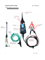
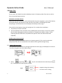
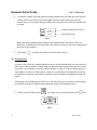
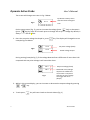
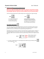
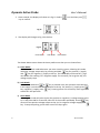
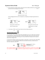
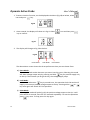
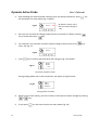
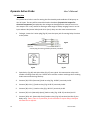
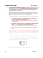
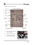
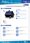
Dynamic Active Probe User’s Manual 1.0 Introduction: This probe is designed to provide an additional help to automotive technicians in trouble shooting of electrical circuits’ problems in the car. Apart from using the normal multi tester, this probe can be used in conjunction with to provide additional functions to assist in diagnosing electrical or components faults or failures in the vehicle. The function of this Dynamic Active Probe has divided into three preferences on the screen main Menus: 1. VOLTS measurement While in this mode, it can test and measure the voltage present in the wire while being tested and can see the voltage condition when compared with the actual battery volts as both the voltages are displayed simultaneous on the screen. This will help us to determine whether are there any resistances in the wire that contribute to the difference in the voltages. 2. ECU wire tests In this mode, the probe will output an adjustable voltage of 0.5V to 5.0V with increments or decrements of 0.5V each step with a fixed constant amperage output of 20 milliamps maximum. This is very useful for simulation of a variety of sensors voltages to fool the ECM/ECU when trouble shooting of sensing problems with an OBD Scanner. 3. Dynamic DC Output for electrical component tests Selecting this mode will provide DC voltage output into two preferences. 3a. Full battery voltage output This first preference will provide battery output to power any electrical components using whatever available voltage in the battery up to maximum 10 Amps output for testing dynamically. Depending on the connections required, it will show positive voltages output or negative (-) output during power out activation. 3b. Adjustable voltage output This second preference will allow the DC power output to be adjustable from 1.0V to 12.0V with increments or decrements of 1.0V each step with a constant amperage output of 5.0 Amps maximum. This feature will allow dynamic testing of a variety of electrical components that operate within these power limits. The displays for both preferences will also show actual Volts, Amps draw and resistance in the circuit during power activation run. 1 Version 1502 Dynamic Active Probe User’s Manual 4. Relay Test This probe also provides testing of the functionality and conditions of Relays with voltage input ranging from 1.0V to 12V DC. With pin markings on the leads, it provide quick and easy hook up before the test. 2.0 Specifications: Operating Voltage: …………………………………..……………… 10.0V ~ 15.0 VDC (Max.) Maximum performance Voltage: ………………………………12.0V ~ 15.0VDC (Max.) Max. Continuous Load: ………….……………………………...….12 Amps (Max.) Full Battery Voltage output: Depends on Battery available Voltage [Max. 10 Amps output] Simulation Voltage output: .…………..…………………..……...0.5V ~ 5.0 VDC [Max. 20mA output] Adjustable Voltage output: …….…………………………… ……1.0V ~ 12.0 VDC [Max. 5A output] Reverse Polarity Protection: ……………….……………..…..…. Built-in (Power supply turn OFF) DC Voltage measuring range: ………………………………..……0.0 V ~ 15.0 V DC Volts Accuracy: …………………………………………….………± 2% Reading Amps measuring range: ………………………….………….……..>100mA ~ 12 A (Max) Amps Accuracy: …………………………………………………….…..± 5% Reading Overload Protections: Power Input at Probe (Built-in): …..….…………………………. 15 Amps (Self recovery) Positive (+) supply at clamp: ………..……..……...……...…….. 20 Amps [Mini ATM Fuse] Power out Activation (Auxiliary ground): …………….….. ...15 Amps [Mini ATM Fuse] Working Temperature: ………………………………………….…..0°C (32°F) ~ 50°C (122°F) Working Humidity: ………………………………………….….……..10% ~ 80% 2 Version 1502 Dynamic Active Probe User’s Manual 3.0 The Dynamic Active Probe: Output or Positive Probe LED indicating lights To 12V Battery terminals LCD Display 5 Wires Relay Cable Activation of power output 15A Mini ATM fuse Power LED indicating lights Auxiliary green lead Common ground (-) 3 Version 1502 Dynamic Active Probe User’s Manual 4.0 Safety precautions: 4 This product is designed to operate on 12V DC battery power source and will be damaged if connected other source of power. Do not test on electrical systems with higher than the rated voltages as specified in this manual. Never attempt to use the instrument if its surface or your hands are wet. Stop using if the instrument operates abnormally. Its safety features may be disabled. Use only shrouded leads and accessories to minimize exposed conductive electrical connections to prevent shock hazard. When use on high current input components, be careful when energizing the component that have moving parts, motors or high power solenoids. Work in well ventilated areas. Do not operate near flammable materials, vapor or dust. Do not open the instrument; there is no serviceable part inside. Warranty will void once opened. Do leave the instrument unattended while connected to a running circuit. Technicians who are not trained or unfamiliar with electrical circuits’ trouble shooting should not use this instrument. The Manufacturer or its Agent will not be liable for any damage to the vehicles or components caused by misuse of this instrument. The Manufacturer or its Agent will not be held liable for any harm caused by unintentional or intentional misuse of this instrument. Version 1502 Dynamic Active Probe User’s Manual 5.0 Begin Test To start with, the Probe has to be hooked up onto a 12V battery either from the car side or from an external battery source. Connection to Power Source Clamp the red clip to positive (+) post and the black clip to the negative (-) post of the battery. Once powered up, pay attention to the red LED at the cable, it should light up when everything is normal and the LCD will display the wakeup screen (Fig.1). The red LED at the battery clamp will not light up if it is under these conditions: 1. The polarity has been reversed. 2. The overload Mini fuse has blown most probably due internal short circuit of the cables that has been damaged severely by pinched or clamped action before. (Note: If after replacing the Mini ATM fuse, the problem still persists then the cable needs to be replaced.) Auxiliary Green Ground Lead This auxiliary green ground lead serves as a Common ground (-) for circuits or electrical components that are not connected to the vehicle chassis ground during testing. 5.1 Voltage Measurement: Once powered up the probe LCD will light up and the screen (Fig.1) will display for a second and then changed to the main Menu (Fig.2). Fig.1 Fig.2 1. Select by pressing or key for volt measurement and then press key. The display will show (Fig.3) as below: Fig.3 12.6 V 0.0 V 5 Supplied Voltage (from Battery) No measurement reading. Version 1502 Dynamic Active Probe User’s Manual 2. To measure voltage, the green cable (common ground) from the probe has to be come in contact with the running circuit at the negative terminal when measuring with the pointed end (+) of the probe. During measurement the display will show an example Fig.3 as below: 12.6 V Supplied Voltage (from Battery) 12.3 V Measured Voltage Fig.3 With both of the voltages shown (Supplied and Measured) we will notice if there is a difference. A difference of more than 0.5V will warrant a check on the circuit to determine the cause of the problem. 3. To exit press key will return back to the main Menu (Fig. 2) 5.2 ECU Wire Test: This test is very useful for troubleshooting of sensor wiring problem after you have checked the sensor’s Volts and Ohms reading using the Multimeter and the problem still exist. Using this probe it can simulate the sensors output voltages in order to verify the wiring going to the ECM/ECU. To do so, an OBD scanner needs to be connected to the diagnostic link (DLC) of ECM/ECU to read the results while connected to the simulation voltage generated by the probe. The voltages can be adjusted from 0.5 Volt to 5.0 Volt (max) with increments or decrements of 0.5V each step with a fixed constant amperage output of 20 milliamps (max). 1. To enter into this mode, select as shown in Fig. 4 below and then press Fig.4 6 Version 1502 key. Dynamic Active Probe User’s Manual The screen will change to as seen in Fig. 5 below. Fig.5 0.5 V By default it always starts with the lowest voltage of 0.5V On the same screen (Fig. 5), you can increase the voltage (press key) or decrease it (press key) by steps of 0.5V each press to change the set point voltage. By default, it always starts with 0.5 Volts. 2. Once the set point voltage has keyed in, press example Fig.6 as below: Fig.6 key. The display will changed to as an 2.0 V Set point Voltage (fixed) 2.0 V Actual Voltage output During testing (example Fig.7), if the voltage detected has a difference of more than 0.2V compared with set point Voltage it will sound the alarm. 2.0 V Set point Voltage (fixed) 1.8 V Measured actual voltage output with a difference of more 0.2 V compared with the set point voltage will trigger the alarm (beeps) Fig.7 3. While in this screen display, you can increase or decrease the output voltage by pressing or key. 4. To exit press 7 key will return back to the main Menu (Fig. 2) Version 1502 Dynamic Active Probe User’s Manual 5.3 Dynamic DC Output for electrical component tests: Extra Precautions: When use on high current (Amps) input components, always be careful when energizing the component that have moving parts, motors or high power solenoids. Do not operate near flammable materials, vapor, gas or dust to avoid any risk of an untoward accident. This test will provide dynamic DC power output with two preferences: (Fig.8 and Fig.9) Fig.8 Fig.9 Full voltage output depends on the voltage available in the battery during testing. Voltage output can be adjusted from 1.0V to 12.0V maximum with increments of 1.0V each step but it also depends on the availability of volts in the battery during testing. Fully Voltage output mode: This mode will provide full DC voltage output to any electrical component under testing using the available voltage derived from the battery that is being connected. It will also provide current up to 10.0 Amps (max) output during the dynamic test. Depending on the connections required, it will show positive voltages output or negative (-) output during power out activation. At the same time it will display (example: Fig. 10) the amperage drawn and the calculated resistance produced by the electrical component under test. Fig.10 12.8 V 8.3 A 1.54 Output Voltage to device Amps Drawn by device Calculated Resistance 1. To access into this function, on the displayed main Menu (Fig.11) as below, select icon and press key. Fig.11 8 Version 1502 Dynamic Active Probe User’s Manual 2. Once entered, the display will show as in Fig.12. Select key to confirm. icon and then press Fig.12 3. The display will change to Fig. 13 as below: Fig.13 Press Mode Lock Mode Pulse Mode The above Menu screen shows the three preferences that you can choose from: a) Press Mode: This is the default mode whenever you enter into this screen. Selecting this mode will allow voltage output only by pressing and hold key for positive (+) supply and key for negative (-) supply to the tip. The LCD display will show the [-] sign next to the volt reading if it is negative supply. The moment you let go the key, the voltage supply stops. b) Lock Mode: In this mode whenever or key is pressed once, the operation locks ON and it will supply a continuous voltage output to the tip. For positive (+) supply press key, negative (-) supply press key. Pressing either one of the keys once again will switch OFF the operation. c) Pulse Mode Selecting this mode will pulse (cycle) the positive or negative (-) voltage output to the tip. It will pulse ON for 3 seconds, then OFF for 3seconds repeatedly. Pressing key once will start positive voltage output to the tip. For negative voltage supply press key. To stop the pulsing, press either one of the keys again. 9 Version 1502 Dynamic Active Probe User’s Manual 4. After deciding the mode of power switching from the above preferences, press proceed to the next display Fig. 14 below. will 12.8 V 0.0 A -.-- Fig.14 No power activation screen During voltage power out to the component, the display as example Fig.15 and 16 as below: 12.8 V 8.3 A 1.54 Fig.15 Fig.16 During power activation with positive voltage output 5. To exit press -12.8 V - 8.3 A 1.54 During power activation with negative ground (-) voltage output key will return back to the main Menu (Fig. 11) Adjustable voltage output: This mode allow the DC power output to be adjustable from 1.0V to 12.0V with increments or decrements of 1.0V each step with a constant amperage output of 5.0 Amps maximum. This feature will allow dynamic testing of a variety of electrical components that operate within these voltage limits. It will show the voltages output during power out activation. At the same time it will display (example: Fig. 17) the amperage drawn and the calculated resistance produced by the electrical component under test. Fig.17 5.0 V 1.6 A 3.13 Set point voltage to device Amps Drawn Calculated Resistance Note: Under this mode, the set voltage will always be a positive (+) output to the tip when key is pressed. Pressing key will have no effect thereby no negative (-) or ground output. 10 Version 1502 Dynamic Active Probe User’s Manual 1. To access into this function, on the displayed main Menu (Fig.18) as below, select icon and press key. Fig.18 2. Once entered, the display will show as in Fig.19. Select key to confirm. icon and then press Fig.19 3. The display will change to Fig. 20 as below: Fig.20 Press Mode Lock Mode Pulse Mode The above Menu screen shows the three preferences that you can choose from: a) Press Mode: This is the default mode whenever you enter into this screen. Selecting this mode will allow voltage output only by pressing and hold key for positive supply only to the tip. The moment you let go the key, the voltage supply stops. b) Lock Mode: In this mode whenever key is pressed once, the operation locks ON and it will supply a continuous positive voltage output to the tip. Pressing either or key once again will switch OFF the operation. c) Pulse Mode Selecting this mode will pulse (cycle) the positive voltage output to the tip. It will pulse ON for 3 seconds, then OFF for 3seconds repeatedly. To start the operation press key once. To stop press this key again. 11 Version 1502 Dynamic Active Probe 4. User’s Manual After deciding the mode of power switching from the above preferences, press will proceed to the next display Fig. 21 below. Fig.21 1.0 V key By default it always starts with the lowest voltage of 1.0V 5. Here you can increase the voltage output by each increment of 1.0V by pressing key or to decrease press key. 6. For example if you need the activation output voltage to be 5.0V just press times. See Fig. 22. key 4 5.0 V Fig.22 7. Press key to confirm and the display will change to Fig. 23 as below. Fig.23 5.0 V 0.0 A -.-- No power activation screen During voltage power out to the component, the display as Fig.24 below: Fig.24 5.0 V 1.6 A 3.13 During power activation 8. While in this screen display, you can increase or decrease the output voltage by pressing or key. 9. To exit press 12 key will return back to the main Menu (Fig. 18) Version 1502 Dynamic Active Probe User’s Manual 5.4 Relay Test This probe has a built-in test for testing the functionality and condition of Relays up to 12V DC input. The test will be controlled under the above [Dynamic DC output for electrical component] test whereby the voltage can be adjusted to control from 1V to 12V output. This is very useful for testing a wide range of Relays ranging from 1V to 12V input where 6.0V (motor bikes) and 12.0V (cars) relays are the most common ones. 1. To begin, insert the 5 wires plug (Fig.25) into the input jack for testing Relay Function at the probe. Fig.25 5 wires plug for testing of Relay function provided. 5 pins Relay Fig.26 13 4 pins Relay Fig.27 2. 5pins Relay (Fig.26) and 4pins Relay (Fig.27) are typical 12V automotive relays with number markings near the pins. Please refer to these number markings when making leads connections during hook up. 3. Connect [30, FEED (Common)] lead to relay (Fig. 26 &27) terminal pin 30. 4. Connect [86, COIL (-)] lead to relay (Fig. 26 & 27) terminal pin 86. 5. Connect [85, COIL (+) lead to relay (Fig. 26 & 27) terminal pin 85. 6. Connect [87, N.O. (Normally Open)] lead to relay (Fig. 26 & 27) terminal pin 87. 7. Connect [87A, N.C. (Normally Close)] lead to relay (Fig. 26) terminal pin 87A (5 pins Relay only). Note: There is no provision for this terminal on 4 pins relays, therefore this lead can be left idle. Version 1502 Dynamic Active Probe User’s Manual 8. You will notice that pin 87A LED1 will be lighted up. (Note: LED 1 will be OFF for 4 pins Relay as there is no connection.) Then adjust the voltage output on the probe using the same procedures as described in pages 11 and 12 earlier to set the voltage according to the relay’s input voltage. 9. Once the output voltage has been set and confirmed with pressing key, press key will activate the Relay and you hear the ‘click’ sound indicating the relay is energised. At this instant, LED 1 will turn OFF and LED2 will turn ON. From the above, we can conclude that the Relay is GOOD under the follow conditions: A. For 5 pins Relays: [Pin 87A, N.C. (Normally Close)] LED 1 lighted up when all the leads are connected to the relay terminals – OK. Note: All 4 pins Relays do not have this terminal. Therefore, LED 1 is OFF since it is not connected. B. During power activation, when the relay energises (‘click’ sound will be heard) and [Pin 87, N.O. (Normally Open)] LED 2 will be lighted up - OK. Note: On 5 pins Relays, [87A, N.C. (Normally Close)] LED 1 will be OFF – OK. C. If one of the above conditions is not met, then the relay can be considered faulty. Note: For those relays that do not have numbers markings, you can still test them as long as you know where the coil input (+) and (-) terminals, the feed voltage (common) terminal, the N.C (Normally Contact) terminal and N.O (Normally Closed) terminal are located. 10. During testing, you may notice the LCD display (example Fig. 27 below) that its’ amp reading is 0.0A and the resistance value is blank. This is because the probe can only read more that 100mA (> 0.1A) reading and if the Relay coil consumes very little current which is less 0.1A, then it will unable to show it and the same goes to the resistance readings. Moreover the main purpose of the test is to test the Relay’s functionality and condition rather that to measuring it. Fig.27 11. To exit press 14 key will return back to the main Menu (Fig. 18). Version 1502 Dynamic Active Probe User’s Manual Disclaimer All information, illustrations, and specifications contained in this user manual are based on the latest information available at the time of printing. The right is reserved to make any changes at any time without obligation to notify any person or organization of such revisions or changes. Furthermore, the manufacturer or its sales agents are not liable for errors contained herein or for incidental or consequential damages (including lost profits) in connection with the furnishing, performance or use of this material. This user manual tells how to use and perform the required procedures on vehicles. Safe and effective use of this tester is very much dependant on the user following the normal practices and procedures outline in this manual. Warranty Information Limited Warranty This limited warranty cover defects in materials and workmanship for a period of twelve (12) months which begins from the date the product is purchased by the end user and is subjected to the following terms and conditions: 1. Within the warranty period, the manufacturer will repair or replace, at their options, any defective parts and return to the owner in good working condition. 2. Any repaired or replaced parts will be warranted for the balance of the original warranty or three months (3) months from the date of repair, whichever is longer. 3. This warranty only extends to the first owner and not assignable or transferable to any subsequent owner. 4. Cost of delivery charges incurred for the repair of the product to and from the manufacturer will be borne by the owner. 5. This limited warranty covers only those defects that arises as a result of normal use and does not cover those that arises as a result of: Unauthorized modifications and repair. Improper operation or misuse. Accident or neglect such as dropping the unit onto hard surfaces. Contact with water, rain or extreme humidity. Contact with extreme heat. 15 Version 1502 Dynamic Active Probe User’s Manual Cables that have broken, bent contact pins or subject to extreme stress or wear. Physical damage to the product surface including scratches, cracks or other damage to the display screen or other externally exposed parts. Limitations of Warranty Other than the foregoing limited warranty, the manufacturer does not make any other warranty or condition of any kind, whether express or implied. Any implied warranty of merchantability, or fitness for use shall be limited to the duration of the foregoing limited warranty. Otherwise, the foregoing limited warranty is the owner’s sole and exclusive remedy and is in lieu of all other warranties whether express or implied. The manufacturer or any of its exclusive sales agents shall not be liable for any consequential or incidental damages or losses arising of the loss of uses of this product. All warranty information, product features and specifications are subjected to change without prior notice. 16 Version 1502