1
MIPSpro™ Assembly Language
Programmer’s Guide
Document Number 007-2418-002
CONTRIBUTORS
Written by Larry Huffman, David Graves
Edited by Larry Huffman, Cindy Kleinfeld
Production by Chris Glazek and David Clarke
Engineering contributions by Bean Anderson, Jim Dehnert, Suneel Jain, Michael
Murphy
© Copyright 1996 Silicon Graphics, Inc.— All Rights Reserved
The contents of this document may not be copied or duplicated in any form, in whole
or in part, without the prior written permission of Silicon Graphics, Inc.
RESTRICTED RIGHTS LEGEND
Use, duplication, or disclosure of the technical data contained in this document by
the Government is subject to restrictions as set forth in subdivision (c) (1) (ii) of the
Rights in Technical Data and Computer Software clause at DFARS 52.227-7013
and/or in similar or successor clauses in the FAR, or in the DOD or NASA FAR
Supplement. Unpublished rights reserved under the Copyright Laws of the United
States. Contractor/manufacturer is Silicon Graphics, Inc., 2011 N. Shoreline Blvd.,
Mountain View, CA 94039-7311.
Silicon Graphics and IRIS are registered trademarks and IRIX, CASEVision, IRIS IM,
IRIS Showcase, Impressario, Indigo Magic, Inventor, IRIS-4D, POWER Series,
RealityEngine, CHALLENGE, Onyx, and WorkShop are trademarks of Silicon
Graphics, Inc. UNIX is a registered trademark of UNIX System Laboratories.
OSF/Motif is a trademark of Open Software Foundation, Inc. The X Window System
is a trademark of the Massachusetts Institute of Technology. PostScript is a registered
trademark and Display PostScript is a trademark of Adobe Systems, Inc.
MIPSpro™ Assembly Language Programmer’s Guide
Document Number 007-2418-002
Contents
List of Figures
List of Tables
vii
ix
About This Guide xi
Audience xi
Topics Covered xii
1.
2.
Registers 1
Register Format 1
General Registers 1
Special Registers 4
Floating Point Registers
Addressing 7
Address Formats 8
Address Descriptions
5
9
3.
Exceptions 11
Main Processor Exceptions 11
Floating Point Exceptions 12
4.
Lexical Conventions 13
Tokens 14
Comments 14
Identifiers 14
Constants 15
Scalar Constants 15
Floating Point Constants
String Constants 17
16
iii
Contents
Multiple Lines Per Physical Line 18
Section and Location Counters 18
Statements 19
Label Definitions 20
Null Statements 20
Keyword Statements 20
Expressions 21
Precedence 21
Expression Operators 22
Data Types 23
Type Propagation in Expressions
5.
iv
25
The Instruction Set 27
Instruction Classes 27
Reorganization Constraints and Rules 27
Instruction Notation 28
Instruction Set 29
Load and Store Instructions 29
Load Instruction Descriptions 31
Store Instruction Descriptions 35
Computational Instructions 38
Computational Instructions 39
Computational Instruction Descriptions 42
Jump and Branch Instructions 54
Jump and Branch Instructions 54
Jump and Branch Instruction Descriptions 56
Special Instructions 59
Special Instruction Descriptions 60
Coprocessor Interface Instructions 60
Coprocessor Interface Summary 61
Coprocessor Interface Instruction Descriptions 62
Contents
6.
Coprocessor Instruction Set 65
Instruction Notation 65
Floating-Point Instructions 66
Floating-Point Formats 67
Floating-Point Load and Store Formats 68
Floating-Point Load and Store Descriptions 69
Floating-Point Computational Formats 70
Floating-Point Computational Instruction Descriptions 73
Floating-Point Relational Operations 74
Floating-Point Relational Instruction Formats 77
Floating-Point Relational Instruction Descriptions 79
Floating-Point Move Formats 81
Floating-Point Move Instruction Descriptions 82
System Control Coprocessor Instructions 82
System Control Coprocessor Instruction Formats 82
System Control Coprocessor Instruction Descriptions 83
Control and Status Register 84
Exception Trap Processing 86
Invalid Operation Exception 87
Division-by-zero Exception 87
Overflow Exception 88
Underflow Exception 89
Inexact Exception 89
Unimplemented Operation Exception 90
Floating-Point Rounding 90
7.
Linkage Conventions 93
Introduction 93
Program Design 94
Register Use and Linkage
The Stack Frame 94
The Shape of Data 101
Examples 101
Learning by Doing 105
94
v
Contents
8.
Pseudo Op-Codes 107
Index
vi
123
List of Figures
Figure 4-1
Figure 6-1
Figure 6-2
Figure 7-1
Figure 7-2
Section and Location Counters 18
Floating Point Formats 67
Floating Control and Status Register 31
Stack Organization 96
Stack Example 98
85
vii
List of Figures
viii
List of Tables
Table 1-1
Table 1-2
Table 1-3
Table 1-4
Table 1-5
Table 2-1
Table 2-2
Table 4-1
Table 4-2
Table 4-3
Table 5-1
Table 5-2
Table 5-3
Table 5-4
Table 5-5
Table 5-6
Table 5-7
Table 5-8
Table 5-9
Table 5-10
Table 5-11
Table 5-12
Table 5-13
Table 6-1
Table 6-2
Table 6-3
Table 6-4
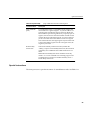
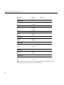
General (Integer) Registers (32-Bit) 2
General (Integer) Registers (64-Bit) 3
Special Registers 4
Floating-Point Registers (32-bit) 5
Floating-Point Registers (64-bit) 6
Address Formats 8
Assembler Addresses 9
Backslash Conventions 17
Expression Operators 22
Data Types 23
Load and Store Format Summary 29
Load Instruction Descriptions 31
Load Instruction Descriptions for MIPS3/4 Architecture Only 34
Store Instruction Descriptions 36
Store Instruction Descriptions for MIPS3/4 Architecture Only 38
Computational Format Summaries 39
Computational Instruction Descriptions 42
Computational Instruction Descriptions for MIPS3/4 Architecture 50
Jump and Branch Format Summary 54
Jump and Branch Instruction Descriptions 56
Special Instruction Descriptions 60
Coprocessor Interface Formats 61
Coprocessor Interface Instruction Descriptions 62
Floating-Point Load and Store Descriptions 69
Floating-Point Computational Instruction Descriptions 73
Floating-Point Relational Operators 75
Floating-Point Relational Instruction Descriptions 79
ix
List of Tables
Table 6-5
Table 6-6
Table 7-1
Table 7-2
Table 8-1
x
Floating-Point Move Instruction Descriptions 82
System Control Coprocessor Instruction Descriptions
Parameter Passing (32-Bit) 99
Parameter Passing (64-Bit) 99
Pseudo Op-Codes 107
83
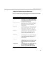
About This Guide
This book describes the assembly language supported by the RISCompiler system, its
syntax rules, and how to write assembly programs. For information on assembling and
linking an assembly language program, see the MIPSpro Compiling, Debugging and
Performance Tuning Guide.
The assembler converts assembly language statements into machine code. In most
assembly languages, each instruction corresponds to a single machine instruction;
however, some assembly language instructions can generate several machine
instructions. This feature results in assembly programs that can run without modification
on future machines, which might have different machine instructions.
In this release of O/S and compiler software, the assembler supports compilations in
both 32-bit and 64-bit mode. Some of the implications of these different data sizes are
explained in this book. For more information, please refer to the MIPSpro 64-Bit Porting
and Transition Guide.
Many assembly language instructions have direct equivalents to machine instructions.
For more information about the operations of a specific arhcitecture, see book that is
appropriate for your machine, for instance, the MIPS R4000 Microprocessor User’s Manual
or the MIPS R8000 Microprocessor User’s Manual.
Audience
This book assumes that you are an experienced assembly language programmer. The
assembler produces object modules from the assembly instructions that the C, and
Fortran 77 compilers generate. It therefore lacks many functions normally present in
assemblers. You should use the assembler only when you need to:
•
Maximize the efficiency of a routine, which might not be possible in C, Fortran 77,,
or another high-level language; for example, to write low-level I/O drivers.
•
Access machine functions unavailable in high-level languages or satisfy special
constraints such as restricted register usage.
xi
About This Guide
•
Change the operating system.
•
Change the compiler system.
Further system information can be obtained from the manuals listed at the end of this
section.
Topics Covered
This book has these chapters:
xii
•
Chapter 1: Registers describes the format for the general registers, the special
registers, and the floating point registers.
•
Chapter 2: Addressing describes how addressing works.
•
Chapter 3: Exceptions describes exceptions you might encounter with assembly
programs.
•
Chapter 4: Lexical Conventions describes the lexical conventions that the
assembler follows.
•
Chapter 5: Instruction Set describes the main processor’s instruction set, including
notation, load and store instructions, computational instructions, and jump and
branch instructions.
•
Chapter 6: Coprocessor Instruction Set describes the coprocessor instruction sets.
•
Chapter 7: Linkage Conventions describes linkage conventions for all supported
high-level languages. It also discusses memory allocation and register use.
•
Chapter 8: Pseudo-Op-Codes describes the assembler’s pseudo-operations
(directives).
•
Index. Contains index entries for this publication.
Chapter 1
1. Registers
This chapter describes the organization of data in memory, and the naming and usage
conventions that the assembler applies to the CPU and FPU registers. See Chapter 7 for
information regarding register use and linkage.
Register Format
The CPU uses four data formats: a 64-bit doubleword, a 32-bit word, a 16-bit halfword
and an 8-bit byte. Byte ordering within each of the larger data formats – doubleword,
word or halfword – the CPU’s byte ordering scheme (or endian issues), affects memory
organization and defines the relationship between address and byte position of data in
memory.
For R4000 and earlier systems, byte ordering is configurable into either big-endian or
little-endian byte ordering (configuration occurs during hardware reset). When
configured as a big-endian system, byte 0 is always the most-significant (leftmost) byte.
When configured as a little-endian system, byte 0 is always the least-significant
(rightmost byte).
The R8000 CPU, at present, supports big-endian only.
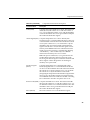
General Registers
For the MIPS1 and MIPS2 architectures, the CPU has thirty-two 32-bit registers. In the
MIPS3 architecture and above, the size of each of the thirty-two integer registers is 64-bit.
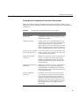
Table 1-1and Table 1-2 summarize the assembler’s usage, conventions and restrictions
for these registers. The assembler reserves all register names; you must use lowercase for
the names. All register names start with a dollar sign($).
The general registers have the names $0..$31. By including the file regdef.h (use #include
<regdef.h>) in your program, you can use software names for some general registers.
1
Chapter 1: Registers
The operating system and the assembler use the general registers $1, $26, $27, $28, and
$29 for specific purposes. Attempts to use these general registers in other ways can
produce unexpected results.
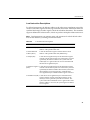
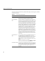
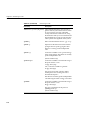
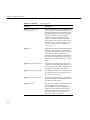
Table 1-1
Register Name
2
General (Integer) Registers (32-Bit)
Software Name
(from regdef.h)
Use and Linkage
$0
Always has the value 0.
$1 or $at
Reserved for the assembler.
$2..$3
v0-v1
Used for expression evaluations and to hold the
integer type function results. Also used to pass
the static link when calling nested procedures.
$4..$7
a0-a3
Pass the first 4 words of actual integer type
arguments; their values are not preserved across
procedure calls.
$8..$11
$11..$15
t0-t7
t4-t7 or
ta0-ta3
Temporary registers used for expression
evaluations; their values aren’t preserved across
procedure calls.
$16..$23
s0-s7
Saved registers. Their values must be preserved
across procedure calls.
$24..$25
t8-t9
Temporary registers used for expression
evaluations; their values aren’t preserved across
procedure calls.
$26..27 or
$kt0..$kt1
k0-k1
Reserved for the operating system kernel.
$28 or $gp
gp
Contains the global pointer.
$29 or $sp
sp
Contains the stack pointer.
$30 or $fp
fp or s8
Contains the frame pointer (if needed);
otherwise a saved register (like s0-s7).
$31
ra
Contains the return address and is used for
expression evaluation.
Register Format
Note: General register $0 always contains the value 0. All other general registers are
equivalent, except that general register $31 also serves as the implicit link register for
jump and link instructions. See Chapter 7 for a description of register assignments.
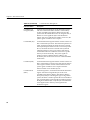
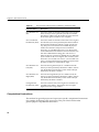
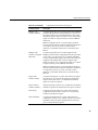
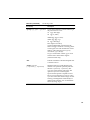
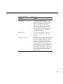
Table 1-2
Register Name
General (Integer) Registers (64-Bit)
Software Name
(from regdef.h)
Use and Linkage
$0
Always has the value 0.
$1 or $at
Reserved for the assembler.
$2..$3
v0-v1
Used for expression evaluations and to hold the
integer type function results. Also used to pass
the static link when calling nested procedures.
$4..$7
$8..$11
a0-a3
a4-a7 or
ta0-ta3
Pass up to 8 words of actual integer type
arguments; their values are not preserved across
procedure calls.
$12..$15
t0-t3
Temporary registers used for expression
evaluations; their values aren’t preserved across
procedure calls.
$16..$23
s0-s7
Saved registers. Their values must be preserved
across procedure calls.
$24..$25
t8-t9
Temporary registers used for expression
evaluations; their values aren’t preserved across
procedure calls.
$26..27 or
$kt0..$kt1
k0-k1
Reserved for the operating system kernel.
$28 or $gp
gp
Contains the global pointer.
$29 or $sp
sp
Contains the stack pointer.
$30 or $fp
fp or s8
Contains the frame pointer (if needed);
otherwise a saved register (such as s0-s7).
$31
ra
Contains the return address and is used for
expression evaluation.
3
Chapter 1: Registers
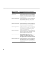
Special Registers
The CPU defines three special registers: PC (program counter), HI and LO, as shown in
Table 1-3. The HI and LO special registers hold the results of the multiplication (mult and
multu) and division (div and divu) instructions.
You usually do not need to refer explicitly to these special registers; instructions that use
the special registers refer to them automatically.
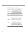
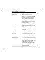
Table 1-3
Special Registers
Name
Description
PC
Program Counter
HI
Multiply/Divide special register holds the most-significant 32
bits of multiply, remainder of divide
LO
Multiply/Divide special register holds the least-significant 32
bits of multiply, quotient of divide
Note: In MIPS3 architecture and later, the HI and Lo registers hold 64-bits.
4
Special Registers
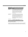
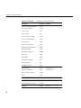
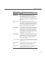
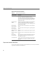
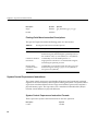
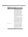
Floating Point Registers
The FPU has sixteen floating-point registers. Each register can hold either a
single-precision (32-bit) or double-precision (64-bit) value. In case of a double-precision
value, $f0 holds the least-significant half, and $f1 holds the most-significant half. For
32-bit systems, all references to these registers use an even register number (for example,
$f4). 64-bit systems can reference all 32 registers directly. Table 1-4 and Table 1-5
summarize the assembler’s usage conventions and restrictions for these registers
.
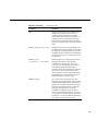
Table 1-4
Floating-Point Registers (32-bit)
Register
Name
Software Name
(from fgregdef.h)
Use and Linkage
$f0..$f2
fv0-fv1
Hold results of floating-point type function ($f0)
and complex type function ($f0 has the real part,
$f2 has the imaginary part.
$f4..$f10
ft0-ft3
Temporary registers, used for expression
evaluation whose values are not preserved across
procedure calls.
$f12..$f14
fa0-fa1
Pass the first two single or double precision
actual arguments; their values are not preserved
across procedure calls.
$f16..$f18
ft4-ft5
Temporary registers, used for expression
evaluation, whose values are not preserved
across procedure calls.
$f20..$f30
fs0-fs5
Saved registers, whose values must be preserved
across procedure calls.
5
Chapter 1: Registers
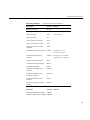
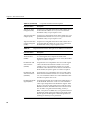
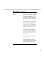
Table 1-5
6
Floating-Point Registers (64-bit)
Register
Name
Software Name
(from fgregdef.h)
Use and Linkage
$f0, $f2
fv0,fv1
Hold results of floating-point type function ($f0)
and complex type function ($f0 has the real part,
$f2 has the imaginary part.
$f1, $f3
$f4..$f11
ft1,ft3
ft0-ft7
Temporary registers, used for expression
evaluation; their values are not preserved across
procedure calls.
$f12..$f19
fa0-fa7
Pass single or double precision actual
arguments, whose values are not preserved
across procedure calls.
$f20..$f23
ft8-ft11
Temporary registers, used for expression
evaluation; their values are not preserved across
proceadure calls.
$f24..$f31
fs0-fs7
Saved registers, whose values must be preserved
across procedure calls.
Chapter 2
2. Addressing
This chapter describes the formats that you can use to specify addresses. SGI CPUs use
a byte addressing scheme. Access to halfwords requires alignment on even byte
boundaries, and access to words requires alignment on byte boundaries that are divisible
by four. Access to doublewords (for 64-bit systems) requires alignment on byte
boundaries that are divisible by eight. Any attempt to address a data item that does not
have the proper alignment causes an alignment exception.
The unaligned assembler load and store instructions may generate multiple machine
language instructions. They do not raise alignment exceptions.
These instructions load and store unaligned data:
•
Load doubleword left (LDL)
•
Load word left (LWL)
•
Load doubleword right (LDR)
•
Load word right (LWR)
•
Store doubleword left (SDL)
•
Store word left (SWL)
•
Store doubleword right (SDR)
•
Store word right (SWR)
•
Unaligned load doubleword (ULD)
•
Unaligned load word (ULW)
•
Unaligned load halfword (ULH)
•
Unaligned load halfword unsigned (ULHU)
•
Unaligned store doubleword (USD)
•
Unaligned store word (USW)
•
Unaligned store halfword (USH)
7
Chapter 2: Addressing
These instructions load and store aligned data
•
Load doubleword (LD)
•
Load word (LW)
•
Load halfword (LH)
•
Load halfword unsigned (LHU)
•
Load byte (LB)
•
Load byte unsigned (LBU)
•
Store doubleword (SD)
•
Store word (SW)
•
Store halfword (SH)
•
Store byte (SB)
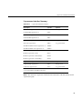
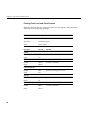
Address Formats
The assembler accepts these formats shown in Table 2-1 for addresses. Table 2-2 explains
these formats in more detail.
Table 2-1
Address Formats
Format
Address
(base register)
Base address (zero offset assumed)
expression
Absolute address
expression (base register)
Based address
index-register (base register)
Based address
relocatable-symbol
Relocatable address
relocatable-symbol + expression
Relocatable address
relocatable-symbol + expression (index Indexed relocatable address
register)
8
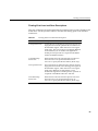
Address Descriptions
Address Descriptions
The assembler accepts any combination of the constants and operations described in this
chapter for expressions in address descriptions.
Table 2-2
Assembler Addresses
Expression
Address Description
( base-register )
Specifies an indexed address, which
assumes a zero offset. The base-register
contents specify the address.
expression
Specifies an absolute address. The
assembler generates the most locally
efficient code for referencing a value at the
specified address.
expression (base-register)
Specifies a based address. To get the
address, the CPU adds the value of the
expression to the contents of the
base-register.
index-register(base-register)
Same as expression(base-register), except that
the index register is used as the offset.
relocatable-symbol
Specifies a relocatable address. The
assembler generates the necessary
instruction(s) to address the item and
generates relocatable information for the
link editor.
relocatable-symbol + expression
Specifies a relocatable address. To get the
address, the assembler adds or subtracts the
value of the expression, which has an
absolute value, from the relocatable symbol.
The assembler generates the necessary
instruction(s) to address the item and
generates relocatable information for the
link editor. If the symbol name does not
appear as a label anywhere in the assembly,
the assembler assumes that the symbol is
external.
9
Chapter 2: Addressing
Table 2-2 (continued)
10
Assembler Addresses
Expression
Address Description
relocatable-symbol (index register)
Specifies an indexed relocatable address. To
get the address, the CPU adds the index
register to the relocatable symbol’s address.
The assembler generates the necessary
instruction(s) to address the item and
generates relocatable information for the
link editor. If the symbol name does not
appear as a label anywhere in the assembly,
the assembler assumes that the symbol is
external.
relocatable + expression
Specifies an indexed relocatable address. To
get the address, the assembler adds or
subtracts the relocatable symbol, the
expression, and the contents of the index
register. The assembler generates the
necessary instruction(s) to address the item
and generates relocation information for the
link editor. If the symbol does not appear as
a label anywhere in the assembly, the
assembler assumes that the symbol is
external.
Chapter 3
3. Exceptions
This chapter describes the exceptions that you can encounter while running assembly
programs. The system detects some exceptions directly, and the assembler inserts specific
tests that signal other exceptions. This chapter lists only those exceptions that occur
frequently.
Main Processor Exceptions
The following exceptions are the most common to the main processor:
•
Address error exceptions, which occur when a data item is referenced that is not on
its proper memory alignment or when an address is invalid for the executing
process.
•
Overflow exceptions, which occur when arithmetic operations compute signed
values and the destination lacks the precision to store the result.
•
Bus exceptions, which occur when an address is invalid for the executing process.
•
Divide-by-zero exceptions, which occur when a divisor is zero.
11
Chapter 3: Exceptions
Floating Point Exceptions
The following are the most common floating point exceptions:
•
12
Invalid operation exceptions which include:
–
Magnitude subtraction of infinities, for example: -1.
–
Multiplication of 0 by 1 with any signs.
–
Division of 0/0 or 1/1 with any signs.
–
Conversion of a binary floating point number to an integer format when an
overflow or the operand value for the infinity or NaN precludes a faithful
representation in the format (see Chapter 4).
–
Comparison of predicates that have unordered operands, and that involve
Greater Than or Less Than without Unordered.
–
Any operation on a signaling NaN.
•
Divide-by-zero exceptions.
•
Overflow exceptions occur when a rounded floating-point result exceeds the
destination format’s largest finite number.
•
Underflow exceptions these occur when a result has lost accuracy and also when a
nonzero result is between 2Emin (2 to the minimum expressible exponent).
•
Inexact exceptions.
Chapter 4
4. Lexical Conventions
This chapter discusses lexical conventions for these topics:
•
Tokens
•
Comments
•
Identifiers
•
Constants
•
Multiple lines per physical line
•
Sections and location counters
•
Statements
•
Expressions
This chapter uses the following notation to describe syntax:
•
| (vertical bar) means “or”
•
[ ] (square brackets) enclose options
•
+ indicates both addition and subtraction operations
13
Chapter 4: Lexical Conventions
Tokens
The assembler has these tokens:
•
Identifiers
•
Constants
•
Operators
The assembler lets you put blank characters and tab characters anywhere between
tokens; however, it does not allow these characters within tokens (except for character
constants). A blank or tab must separate adjacent identifiers or constants that are not
otherwise separated.
Comments
The pound sign character (#) introduces a comment. Comments that start with a # extend
through the end of the line on which they appear. You can also use C-language notation
/*...*/ to delimit comments.
The assembler uses cpp (the C language preprocessor) to preprocess assembler code.
Because cpp interprets #s in the first column as pragmas (compiler directives), do not start
a # comment in the first column.
Identifiers
An identifier consists of a case-sensitive sequence of alphanumeric characters, including
these:
•
. (period)
•
_ (underscore)
•
$ (dollar sign)
The first character of an identifier cannot be numeric.
14
Constants
If an identifier is not defined to the assembler (only referenced), the assembler assumes
that the identifier is an external symbol. The assembler treats the identifier like a .globl
pseudo-operation (see Chapter 8). If the identifier is defined to the assembler and the
identifier has not been specified as global, the assembler assumes that the identifier is a
local symbol.
Constants
The assembler has these constants:
•
Scalar constants
•
Floating point constants
•
String constants
Scalar Constants
The assembler interprets all scalar constants as twos-complement numbers. In 32-bit
mode, a scalar constant is 32 bits. 64 bits is the size of a scalar constant in 64-bit mode.
Scalar constants can be any of the alphanumeric characters 0123456789abcdefABCDEF.
Scalar constants can be one of these constants:
•
Decimal constants, which consist of a sequence of decimal digits without a leading
zero.
•
Hexadecimal constants, which consist of the characters 0x (or 0X) followed by a
sequence of digits.
•
Octal constants, which consist of a leading zero followed by a sequence of digits in
the range 0..7.
15
Chapter 4: Lexical Conventions
Floating Point Constants
Floating point constants can appear only in .float and .double pseudo-operations
(directives), see Chapter 8, and in the floating point Load Immediate instructions, see
Chapter 6. Floating point constants have this format:
+d1[.d2][e|E+d3]
where:
•
d1 is written as a decimal integer and denotes the integral part of the floating point
value.
•
d2 is written as a decimal integer and denotes the fractional part of the floating
point value.
•
d3 is written as a decimal integer and denotes a power of 10.
•
The “+” symbol is optional.
For example:
21.73E–3
represents the number .02173.
Optionally, .float and .double directives may use hexadecimal floating point constants
instead of decimal ones. A hexadecimal floating point constant consists of:
<+ or –> 0x <1 or 0 or nothing> . <hex digits> H 0x <hex digits>
The assembler places the first set of hex digits (excluding the 0 or 1 preceding the decimal
point) in the mantissa field of the floating point format without attempting to normalize
it. It stores the second set of hex digits into the exponent field without biasing them. It
checks that the exponent is appropriate if the mantissa appears to be denormalized.
Hexadecimal floating point constants are useful for generating IEEE special symbols,
and for writing hardware diagnostics.
For example, either of the following generates a single-precision “1.0”:
.float 1.0e+0
.float 0x1.0h0x7f
16
Constants
String Constants
String constants begin and end with double quotation marks (”).
The assembler observes C language backslash conventions. For octal notation, the
backslash conventions require three characters when the next character can be confused
with the octal number. For hexadecimal notation, the backslash conventions require two
characters when the next character can be confused with the hexadecimal number (that
is,, use a 0 for the first character of a single character hex number).
The assembler follows the backslash conventions shown in Table 4-1.
Table 4-1
Backslash Conventions
Convention
Meaning
\a
Alert (0x07)
\b
Backspace (0x08)
\f
Form feed (0x0c)
\n
Newline (0x0a)
\r
Carriage return (0x0d)
\t
horizontal tab (0x09)
\v
Vertical feed (0x0b)
\\
Backslash (0x5c)
\"
Double quotation mark (0x22)
\’
Single quotation mark (0x27)
\000
Character whose octal value is 000
\Xnn
Character whose hexadecimal value is nn
17
Chapter 4: Lexical Conventions
Multiple Lines Per Physical Line
You can include multiple statements on the same line by separating the statements with
semicolons. The assembler does not recognize semicolons as separators when they
follow comment symbols (# or /*).
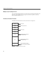
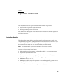
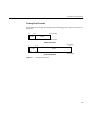
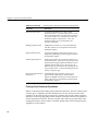
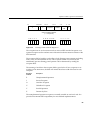
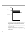
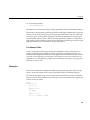
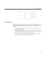
Section and Location Counters
Assembled code and data fall in one of the sections shown in Figure 4-1.
.text
.rdata
Text section
Read-only data section
.data
.lit8
Data sections
.lit4
.sdata
Small data section, addressed
through register $gp
.sbss
Small bss section, addressed
through register $gp
.bss
bss (block started by storage)
section, which loads zero-initialized
data
Figure 4-1
18
Section and Location Counters
Statements
The assembler always generates the text section before other sections. Additions to the
text section happen in four-byte units. Each section has an implicit location counter,
which begins at zero and increments by one for each byte assembled in the section.
The bss section holds zero-initialized data. If a .lcomm pseudo-op defines a variable (see
Chapter 8), the assembler assigns that variable to the bss (block started by storage) section
or to the sbss (short block started by storage) section depending on the variable’s size.
The default variable size for sbss is 8 or fewer bytes.
The command line option –G for each compiler (C, Pascal, Fortran 77, or the assembler),
can increase the size of sbss to cover all but extremely large data items. The link editor
issues an error message when the –G value gets too large. If a –G value is not specified
to the compiler, 8 is the default. Items smaller than, or equal to, the specified size go in
sbss. Items greater than the specified size go in bss.
Because you can address items much more quickly through $gp than through a more
general method, put as many items as possible in sdata or sbss. The size of sdata and sbss
combined must not exceed 64K bytes.
Statements
Each statement consists of an optional label, an operation code, and the operand(s). The
system allows these statements:
•
Null statements
•
Keyword statements
19
Chapter 4: Lexical Conventions
Label Definitions
A label definition consists of an identifier followed by a colon. Label definitions assign
the current value and type of the location counter to the name. An error results when the
name is already defined, the assigned value changes the label definition, or both
conditions exist.
Label definitions always end with a colon. You can put a label definition on a line by
itself.
A generated label is a single numeric value (1...255). To reference a generated label, put
an f (forward) or a b (backward) immediately after the digit. The reference tells the
assembler to look for the nearest generated label that corresponds to the number in the
lexically forward or backward direction.
Null Statements
A null statement is an empty statement that the assembler ignores. Null statements can
have label definitions. For example, this line has three null statements in it:
label: ; ;
Keyword Statements
A keyword statement begins with a predefined keyword. The syntax for the rest of the
statement depends on the keyword. All instruction opcodes are keywords. All other
keywords are assembler pseudo-operations (directives).
20
Expressions
Expressions
An expression is a sequence of symbols that represent a value. Each expression and its
result have data types. The assembler does arithmetic in twos-complemet integers (32
bits of precision in 32-bit mode; 64 bits of precision in 64-bit mode). Expressions follow
precedence rules and consist of:
•
Operators
•
Identifiers
•
Constants
Also, you may use a single character string in place of an integer within an expression.
Thus:
.byte “a” ; .word “a”+0x19
is equivalent to:
.byte 0x61 ; .word 0x7a
Precedence
Unless parentheses enforce precedence, the assembler evaluates all operators of the same
precedence strictly from left to right. Because parentheses also designate index-registers,
ambiguity can arise from parentheses in expressions. To resolve this ambiguity, put a
unary + in front of parentheses in expressions.
The assembler has three precedence levels, which are listed here from lowest to highest
precedence
least binding,
binary
+,-
binary
*,/,5,<<,>>,^,&, |
unary
-,+,~
lowest precedence
.
.
.
most binding,
highest precedence
Note: The assembler’s precedence scheme differs from that of the C language.
21
Chapter 4: Lexical Conventions
Expression Operators
For expressions, you can rely on the precedence rules, or you can group expressions with
parentheses. The assembler recognizes the operators listed in Table 4-2.
22
Table 4-2
Expression Operators
Operator
Meaning
+
Addition
-
Subtraction
*
Multiplication
/
Division
%
Remainder
<<
Shift Left
>>
Shift Right (sign NOT extended)
^
Bitwise Exclusive-OR
&
Bitwise AND
|
Bitwise OR
-
Minus (unary)
+
Identity (unary)
~
Complement
Expressions
Data Types
The assembler manipulates several types of expressions. Each symbol you reference or
define belongs to one of the categories shown in Table 4-3.
Table 4-3
Data Types
Type
Description
undefined
Any symbol that is referenced but not defined becomes global
undefined, and this module will attempt to import it. The
assembler uses 32-bit addressing to access these symbols.
(Declaring such a symbol in a. globl pseudo-op merely makes its
status clearer).
sundefined
A symbol defined by a .extern pseudo-op becomes global small
undefined if its size is greater than zero but less than the number
of bytes specified by the –G option on the command line (which
defaults to 8). The linker places these symbols within a 64KB
region pointed to by the $gp register, so that the assembler can
use economical 16-bit addressing to access them.
absolute
A constant defined in an “=” expression.
text
The text section contains the program’s instructions, which are
not modifiable during execution. Any symbol defined while the
.text pseudo-op is in effect belongs to the text section.
data
The data section contains memory that the linker can initialize to
nonzero values before your program begins to execute. Any
symbol defined while the .data pseudo-op is in effect belongs to
the data section. The assembler uses 32-bit or 64-bit addressing to
access these symbols (depending on whether you are in 32-bit or
64-bit mode).
sdata
This category is similar to data, except that defining a symbol
while the .sdata (“small data”) pseudo-op is in effect causes the
linker to place it within a 64KB region pointed to by the $gp
register, so that the assembler can use economical 16-bit
addressing to access it.
23
Chapter 4: Lexical Conventions
Table 4-3
Data Types
Type
Description
rdata
Any symbol defined while the .rdata pseudo-op is in effect
belongs to this category, which is similar to data, but may not be
modified during execution.
bss and sbss
The bss and sbss sections consist of memory which the kernel
loader initializes to zero before your program begins to execute.
Any symbol defined in a .comm or .lcomm pseudo-op belongs to
these sections (except that a .data, .sdata, or .rdata pseudo-op can
override a .comm directive). If its size is less than the number of
bytes specified by the –G option on the command line (which
defaults to 8), it belongs to sbss (“small bss”), and the linker
places it within a 64k byte region pointed to by the $gp register so
that the assembler can use economical 16-bit addressing to access
it. Otherwise, it belongs to bss and the assembler uses 32-bit or
64-bit addressing (depending on whether you are in 32-bit or
64-bit mode). Local symbols in bss or sbss defined by .lcomm are
allocated memory by the assembler; global symbols are allocated
memory by the link editor; and symbols defined by .comm are
overlaid upon like-named symbols (in the fashion of Fortran
“COMMON” blocks) by the link editor.
Symbols in the undefined and small undefined categories are always global (that is, they
are visible to the link editor and can be shared with other modules of your program).
Symbols in the absolute, text, data, sdata, rdata, bss, and sbss categories are local unless
declared in a .globl pseudo-op.
24
Expressions
Type Propagation in Expressions
When expression operators combine expression operands, the result’s type depends on
the types of the operands and on the operator. Expressions follow these type propagation
rules:
•
If an operand is undefined, the result is undefined.
•
If both operands are absolute, the result is absolute.
•
If the operator is + and the first operand refers to a relocatable text-section,
data-section, bss-section, or an undefined external, the result has the postulated type
and the other operand must be absolute.
•
If the operator is – and the first operand refers to a relocatable text-section,
data-section, or bss-section symbol, the second operand can be absolute (if it
previously defined) and the result has the first operand’s type; or the second
operand can have the same type as the first operand and the result is absolute. If the
first operand is external undefined, the second operand must be absolute.
•
The operators * , /, % , << , >> , ~, ^ , & , and | apply only to absolute symbols.
25
Chapter 5
5. The Instruction Set
This chapter describes instruction notation and discusses assembler instructions for the
main processor. Chapter 6 describes coprocessor notation and instructions.
Instruction Classes
The assembler has these classes of instructions for the main processor:
•
Load and Store Instructions. These instructions load immediate values and move
data between memory and general registers.
•
Computational Instructions. These instructions do arithmetic and logical
operations for values in registers.
•
Jump and Branch Instructions. These instructions change program control flow.
In addition, there are two other classes of instruction:
•
Coprocessor Interface. These instructions provide standard interfaces to the
coprocessors.
•
Special Instructions. These instructions do miscellaneous tasks.
Reorganization Constraints and Rules
To maximize performance, the goal of RISC designs is to achieve an execution rate of one
machine cycle per instruction. When writing assembly language instructions, you must
be aware of the rules to achieve this goal. This information is given in the MIPS R4000
Microprocessor User’s Manual (published by Prentice Hall) or the MIPS R8000
Microprocessor User’s Manual, depending on which architecture you are using.
27
Chapter 5: The Instruction Set
Instruction Notation
The tables in this chapter list the assembler format for each load, store, computational,
jump, branch, coprocessor, and special instruction. The format consists of an op-code and
a list of operand formats. The tables list groups of closely related instructions; for those
instructions, you can use any op-code with any specified operand.
Operands can take any of these formats:
•
Memory references. For example, a relocatable symbol +/– an expression(register).
•
Expressions (for immediate values).
•
Two or three operands. For example, ADD $3,$4 is the same as ADD $3,$3,$4.
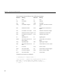
The operands in the table in this chapter have the following meanings
28
Operand
Description
address
Symbolic expression (see Chapter2)
breakcode
Value that determines the break
destination
Destination register
destination/src1
Destination register is also source register 1
dest-copr
Destination coprocessor register
dest-gpr
Destination general register
expression
Absolute value
immediate
Expression with an immediate value
label
Symbolic label
operation
Coprocessor-specific operation
return
Register containing the return address
source
Source register
src1, src2
Source registers
src-copr
Coprocessor register from which values are assigned
src-gpr
General register from which values are assigned
target
Register containing the target
z
Coprocessor number in the range 0..2
Instruction Set
Instruction Set
The tables in this section summarize the assembly language instruction set. Most of the
assembly language instructions have direct machine equivalents.
Load and Store Instructions
Load and store are immediate type intructions that move data between memory and the
general registers. Table 5-1 summarizes the load and store instruction format, and
Table 5-2 and Table 5-3 provide more detailed descriptions for each load instruction.
Table 5-4 and Table 5-5 provide details of each store instruction.
Table 5-1
Load and Store Format Summary
Description
Op-code
Operands
Load Address
LA
destination, address
Load Doubleword Address
DLA
Load Byte
LB
Load Byte Unsigned
LBU
Load Halfword
LH
Load Halfword Unsigned
LHU
Load Linked*
LL
Load Word
LW
Load Word Left
LWL
Load Word Right
LWR
Load Doubleword
LD
Unaligned Load Halfword
ULH
Unaligned Load Halfword
Unsigned
ULHU
Unaligned Load Word
ULW
Load Immediate
LI
destination, expression
29
Chapter 5: The Instruction Set
Table 5-1 (continued)
Load and Store Format Summary
Description
Op-code
Load Doublewod Immediate
DLI
Store Double Right
SDR
Operands
Unaligned Store Doubleword USD
Load Upper Immediate
LUI
Store Byte
SB
Store Conditional *
SC
Store Double
SD
Store Halfword
SH
Store Word Left
SWL
Store Word Right
SWR
Store Word
SW
Unaligned Store Halfword
USH
Unaligned Store Word
USW
Load Doubleword
LD
Load Linked Doubleword
LLD
Load Word Unsigned
LWU
Load Doubleword Left
LDL
Load Doubleword Right
LDR
Unaligned Load Double
ULD
Store Doubleword
SD
Store Conditional
Doubleword
SCD
Store Double Left
SDL
* Not valid in MIPS1 architectures
30
source, address
destination, address
source, address
Instruction Set
Load Instruction Descriptions
For all load instructions, the effective address is the 32-bit twos-complement sum of the
contents of the index-register and the (sign-extended) 16-bit offset. Instructions that have
symbolic labels imply an index register, which the assembler determines. The assembler
supports additional load instructions, which can produce multiple machine instructions.
Note: Load instructions can generate many code sequences for which the link editor
must fix the address by resolving external data items.
Table 5-2
Load Instruction Descriptions
Instruction Name
Description
Load Address (LA)
Loads the destination register with the effective 32-bit
address of the specified data item.
Load Doubleword
Address (DLA)
Loads the destination register with the effective 64-bit
address of the specified data item (MIPS4 only).
Load Byte (LB)
Loads the least-significant byte of the destination register
with the contents of the byte that is at the memory location
specified by the effective address. The system treats the
loaded byte as a signed value: bit seven is extended to fill
the three most-significant bytes.
Load Byte Unsigned Loads the least-significant byte of the destination register
(LBU)
with the contents of the byte that is at the memory location
specified by the effective address. Because the system treats
the loaded byte as an unsigned value, it fills the three
most-significant bytes of the destination register with zeros.
Load Halfword (LH) Loads the two least-significant bytes of the destination
register with the contents of the halfword that is at the
memory location specified by the effective address. The
system treats the loaded halfword as a signed value. If the
effective address is not even, the system signals an address
error exception.
31
Chapter 5: The Instruction Set
Table 5-2 (continued)
32
Load Instruction Descriptions
Instruction Name
Description
Load Halfword
Unsigned (LHU)
Loads the least-significant bits of the destination register
with the contents of the halfword that is at the memory
location specified by the effective address. Because the
system treats the loaded halfword as an unsigned value, it
fills the two most-significant bytes of the destination
register with zeros. If the effective address is not even, the
system signals an address error exception.
Load Linked (LL) *
Loads the destination register with the contents of the word
that is at the memory location. This instruction performs an
SYNC operation implicitly; all loads and stores to shared
memory fetched prior to the LL must access memory before
the LL, and loads and stores to shared memory fetched
subsequent to the LL must access memory after the LL.
Load Linked and Store Conditional can be use to update
memory locations atomically. The system signals an
address exception when the effective address is not
divisible by four. *This instruction is not valid in the MIPS1
architectures.
Load Word (LW)
Loads the destination register with the contents of the word
that is at the memory location. The system replaces all bytes
of the register with the contents of the loaded word. The
system signals an address error exception when the
effective address is not divisible by four.
Load Word Left
(LWL)
Loads the sign; that is, Load Word Left loads the destination
register with the most-significant bytes of the word
specified by the effective address. The effective address
must specify the byte containing the sign. In a big-endian
system, the effective address specifies the lowest numbered
byte; in a little-endian system, the effective address specifies
the highest numbered byte. Only the bytes which share the
same aligned word in memory are merged into the
destination register.
Instruction Set
Table 5-2 (continued)
Load Instruction Descriptions
Instruction Name
Description
Load Word Right
(LWR)
Loads the lowest precision bytes; that is, Load Word Right
loads the destination register with the least-significant bytes
of the word specified by the effective address. The effective
address must specify the byte containing the
least-significant bits. In a big-endian configuration, the
effective address specifies the highest numbered byte; in a
little-endian configuration, the effective address specifies
the lowest numbered byte. Only the bytes which share the
same aligned word in memory are merged into the
destination register.
Load Doubleword
(LD)
LD is a machine instruction in the MIPS3 architecture. For
the -mips1 [default] and -mips2 option: Loads the register
pair (destination and destination +1) with the two successive
words specified by the address. The destination register
must be the even register of the pair. When the address is
not on a word boundary, the system signals an address error
exception.
Note: This is retained for use with the -mips1 and -mips2
options to provide backward compatibility only.
Unaligned Load
Halfword (ULH)
Loads a halfword into the destination register from the
specified address and extends the sign of the halfword.
Unaligned Load Halfword loads a halfword regardless of
the halfword’s alignment in memory.
Unaligned Load
Halfword Unsigned
(ULHU)
Loads a halfword into the destination register from the
specified address and zero extends the halfword. Unaligned
Load Halfword Unsigned loads a halfword regardless of
the halfword’s alignment in memory.
Unaligned Load
Word (ULW)
Loads a word into the destination register from the
specified address. Unaligned Load Word loads a word
regardless of the word’s alignment in memory.
Load Immediate (LI) Loads the destination register with the 32-bit value of an
expression that can be computed at assembly time.
Note: Load Immediate can generate any efficient code
sequence to put a desired value in the register.
33
Chapter 5: The Instruction Set
Table 5-2 (continued)
Load Instruction Descriptions
Instruction Name
Description
Load Doubleword
Immediate (DLI)
Loads the destination register with the 64-bit value of an
expression that can be computed at assembly time.
Note: Load Immediate can generate any efficient code
sequence to put a desired value in the register (MIPS4 only).
Load Upper
Immediate (LUI)
Table 5-3
34
Loads the most-significant half of a register with the
expression’s value. The system fills the least-significant half
of the register with zeros. The expression’s value must be in
the range –32768...65535.
Load Instruction Descriptions for MIPS3/4 Architecture Only
Instruction Name
Description
Load Doubleword
(LD)
Loads the destination register with the contents of the
doubleword that is at the memory location. The system
replaces all bytes of the register with the contents of the
loaded doubleword. The system signals an address error
exception when the effective address is not divisible by
eight.
Load Linked
Doubleword (LLD)
Loads the destination register with the contents of the
doubleword that is currently in the memory location. This
instruction performs a SYNC operation implicitly. Load
Linked Doubleword and Store Conditional Doubleword can
be used to update memory locations atomically.
Load Word
Unsigned (LWU)
Loads the least-significant bits of the destination register
with the contents of the word (32 bits) that is at the memory
location specified by the effective address. Because the
system treats the loaded word as an unsigned value, it fills
the four most-significant bytes of the destination register
with zeros. If the effective address is not divisible by four,
the system signals an address error exception.
Instruction Set
Table 5-3 (continued)
Load Instruction Descriptions for MIPS3/4 Architecture Only
Instruction Name
Description
Load Doubleword
Left (LDL)
Loads the destination register with the most-significant
bytes of the doubleword specified by the effective address.
The effective address must specify the byte containing the
sign. In a big-endian configuration, the effective address
specifies the lowest numbered byte; in a little-endian
machine, the effective address specifies the highest
numbered byte. Only the bytes which share the same
aligned doubleword in memory are merged into the
destination register.
Load Doubleword
Right (LDR)
Loads the destination register with the least-significant
bytes of the doubleword specified by the effective address.
The effective address must specify the byte containing the
least-significant bits. In a bid-endian machine, the effective
address specifies the highest numbered byte. In a
little-endian machine, the effective address specifies the
lowest numbered byte. Only the bytes which share the same
aligned doubleword in memory are merged into the
destination register.
Unaligned Load
Doubleword (ULD)
Loads a doubleword into the destination register from the
specified address. ULD loads a doubleword regardless of
the doubleword’s alignment in memory.
Store Instruction Descriptions
For all machine store instructions, the effective address is the 32-bit twos-complement
sum of the contents of the index-register and the (sign-extended) 16-bit offset. The
assembler supports additional store instructions, which can produce multiple machine
35
Chapter 5: The Instruction Set
instructions. Instructions that have symbolic labels imply an index-register, which the
assembler determines.
Table 5-4
Store Instruction Descriptions
Instruction Name
Description
Store Byte (SB)
Stores the contents of the source register’s least-significant
byte in the byte specified by the effective address.
Store Conditional*
(SC)
Stores the contents of a word from the source register into
the memory location specified by the effective address. This
instruction implicitly performs a SYNC operation; all loads
and stores to shared memory fetched prior to the sc must
access memory before the sc, and loads and stores to shared
memory fetched subsequent to the sc must access memory
after the sc. If any other processor or device has modified
the physical address since the time of the previous Load
Linked instruction, or if an RFE or ERET instruction occurs
between the Load Linked and this store instruction, the
store fails. The success or failure of the store operation (as
defined above) is indicated by the contents of the source
register after execution of the instruction. A successful store
sets it to 1; and a failed store sets it to 0. The machine signals
an address exception when the effective address is not
divisible by four. *This instruction is not valid in the MIPS1
architectures.
Store Doubleword
(SD)
SD is a machine instruction in the MIPS3 architecture. For
the -mips1 [default] and -mips2 options: Stores the
contents of the register pair in successive words, which the
address specifies. The source register must be the even
register of the pair, and the storage address must be word
aligned.
Note: This is retained for use with the -mips1 and -mips2
options to provide backward compatibility only.
Store Halfword (SH) Stores the two least-significant bytes of the source register in
the halfword that is at the memory location specified by the
effective address. The effective address must be divisible by
two; otherwise the machine signals an address error
exception.
36
Instruction Set
Table 5-4 (continued)
Store Instruction Descriptions
Instruction Name
Description
Store Word Left
(SWL)
Stores the most-significant bytes of a word in the memory
location specified by the effective address. The contents of
the word at the memory location, specified by the effective
address, are shifted right so that the leftmost byte of the
unaligned word is in the addressed byte position. The
stored bytes replace the corresponding bytes of the effective
address. The effective address’s last two bits determine how
many bytes are involved.
Store Word Right
(SWR)
Stores the least-significant bytes of a word in the memory
location specified by the effective address. The contents of
the word at the memory location, specified by the effective
address, are shifted left so that the right byte of the
unaligned word is in the addressed byte position. The
stored bytes replace the corresponding bytes of the effective
address. The effective address’s last two bits determine how
many bytes are involved.
Store Word (SW)
Stores the contents of a word from the source register in the
memory location specified by the effective address. The
effective address must be divisible by four; otherwise the
machine signals an address error exception.
Unaligned Store
Halfword (USH)
Stores the contents of the two least-significant bytes of the
source register in a halfword that the address specifies. The
machine does not require alignment for the storage address.
Unaligned Store
Word (USW)
Stores the contents of the source register in a word specified
by the address. The machine does not require alignment for
the storage address.
37
Chapter 5: The Instruction Set
Table 5-5
Store Instruction Descriptions for MIPS3/4 Architecture Only
Instruction Name
Description
Store Doubleword
(SD)
Stores the contents of a doubleword from the source register
in the memory location specified by the effective address.
The effective address must be divisible by eight, otherwise
the machine signals an address error exception.
Store Conditional
Doubleword (SCD)
Stores the contents of a doubleword from the source register
into the memory locations specified by the effective address.
This instruction implicitly performs a SYNC operation. If
any other processor or device has modified the physical
address since the time of the previous Load Linked
instruction, or if an ERET instruction occurs between the
Load Linked instruction and this store instruction, the store
fails and is inhibited from taking place. The success or
failure of the store operation (as defined above) is indicated
by the contents of the source register after execution of this
instruction. A successful store sets it to 1; and a failed store
sets it to 0. The machine signals an address exception when
the effective address is not divisible by eight.
Store Doubleword
Left (SDL)
Stores the most-significant bytes of a doubleword in the
memory location specified by the effective address. It alters
only the doubleword in memory which contains the byte
indicated by the effective address.
Store Doubleword
Right (SDR)
Stores the least-significant bytes of a doubleword in the
memory location specified by the effective address. It alters
only the doubleword in memory which contains the byte
indicated by the effective address.
Unaligned Store
Doubleword (USD)
Stores the contents of the source register in a doubleword
specified by the address. The machine does not require
alignment for the storage address.
Computational Instructions
The machine has general-purpose and coprocessor-specific computational instructions
(for example, the floating-point coprocessor). This part of the book describes
general-purpose computational instructions.
38
Computational Instructions
Computational Instructions
Computational instructions perform the following operations on register values;
•
arithmetic
•
logical
•
shift
•
multiply
•
divide
Table 5-6 summarizes the computational format summaries, and Table 5-7 and Table 5-8
describe these instructions in more detail.
Table 5-6
Computational Format Summaries
Description
Op-code
Operand
Add with Overflow
ADD
destination, src1, src2
Add without Overflow
ADDU
destination, src1, src2
AND
AND
destination, src1, immediate
Divide Signed
DIV
destination/src1, immediate
Divide Unsigned
DIVU
Exclusive-OR
XOR
Multiply
MUL
Multiply with Overflow
MULO
Multiply with Overflow
Unsigned
MULOU
NOT OR
NOR
OR
OR
Set Equal
SEQ
Set Greater Than
SGT
Set Greater/Equal
SGE
39
Chapter 5: The Instruction Set
Table 5-6 (continued)
40
Computational Format Summaries
Description
Op-code
Operand
Set Greater/Equal Unsigned
SGEU
Set Greater Unsigned
SGTU
Set Less Than
SLT
Set Less/Equal
SLE
Set Less/Equal Unsigned
SLEU
Set Less Than Unsigned
SLTU
Set Not Equal
SNE
Subtract with Overflow
SUB
Subtract without Overflow
SUBU
Remainder Signed
REM
Remainder Unsigned
REMU
Rotate Left
ROL
Rotate Right
ROR
Shift Right Arithmetic
SRA
Shift Left Logical
SLL
Shift Right Logical
SRL
Absolute Value
ABS
destination, src1
Negate with Overflow
NEG
destination/src1
Negate without Overflow
NEGU
NOT
NOT
Move
MOVE
destination, src1
Move Conditional on Not Zero
MOVN
destination, src1, src2
Move Conditional on Zero
MOVZ
Multiply
MULT
src1,src2
Computational Instructions
Table 5-6 (continued)
Computational Format Summaries
Description
Op-code
Operand
Multiply Unsigned
MULTU
Trap if Equal
TEQ
src1, src2
Trap if not Equal
TNE
src1, immediate
Trap if Less Than
TLT
Trap if Less than, Unsigned
TLTU
Trap if Greater Than or Equal
TGE
Trap if Greater than or Equal,
Unsigned
TGEU
Doubleword Add with Overflow DADD
destination,src1, src2
destination/src1,src2
Doubleword Add without
Overflow
DADDU
destination, src1, immediate
Doubleword Divide Signed
DDIV
Doubleword Divide Unsigned
DDIVU
Doubleword Multiply
DMUL
Doubleword Multiply with
Overflow
DMULO
Doubleword Multiply with
Overflow Unsigned
DMULO
U
Doubleword Subtract with
Overflow
DSUB
Doubleword Subtract without
Overflow
DSUBU
destination/src1, immediate
Description
Op-code
Doubleword Remainder Signed
DREM
Operand
Doubleword Remainder Unsigned DREMU
41
Chapter 5: The Instruction Set
Description
Op-code
Operand
Doubleword Rotate Left
DROL
Doubleword Rotate Right
DROR
Doubleword Shift Right
Arithmetic
DSRA
Doubleword Shift Left Logical
DSLL
Doubleword Shift Right Logical
DSRL
Doubleword Absolute Value
DABS
destination, src1
Doubleword Negate with
Overflow
DNEG
destination/src1
Doubleword Negate without
Overflow
DNEGU
Doubleword Multiply
DMULT
src1, src2
Doubleword Multiply Unsigned
DMULT
U
src1, immediate
Computational Instruction Descriptions
Table 5-7
42
Computational Instruction Descriptions
Instruction Name
Description
Absolute Value
(ABS)
Computes the absolute value of the contents of src1 and puts
the result in the destination register. If the value in src1 is
–2147483648, the machine signals an overflow exception.
Add with Overflow
(ADD)
Computes the twos-complement sum of two signed values.
This instruction adds the contents of src1 to the contents of
src2, or it can add the contents of src1 to the immediate value.
Add (with Overflow) puts the result in the destination
register. When the result cannot be extended as a 32-bit
number, the machine signals an overflow exception.
Add without
Overflow (ADDU)
Computes the twos-complement sum of two 32-bit values.
This instruction adds the contents of src1 to the contents of
src2, or it can add the contents of src1 to the immediate value.
Add (without Overflow) puts the result in the destination
register. Overflow exceptions never occur.
Computational Instructions
Table 5-7 (continued)
Computational Instruction Descriptions
Instruction Name
Description
AND (AND)
Computes the Logical AND of two values. This instruction
ANDs (bit-wise) the contents of src1 with the contents of
src2, or it can AND the contents of src1 with the immediate
value. The immediate value is not sign extended. AND puts
the result in the destination register.
Divide Signed (DIV) Computes the quotient of two values. Divide (with
Overflow) treats src1 as the dividend. The divisor can be src2
or the immediate value. The instruction divides the contents
of src1 by the contents of src2, or it can divide src1 by the
immediate value. It puts the quotient in the destination
register. If the divisor is zero, the machine signals an error
and may issue a BREAK instruction. The DIV instruction
rounds toward zero. Overflow is signaled when dividing
–2147483648 by –1. The machine may issue a BREAK
instruction for divide-by-zero or for overflow.
Note: The special case DIV $0,src1,src2 generates the real
machine divide instruction and leaves the result in the
HI/LO register. The HI register contains the remainder and
the LO register contains the quotient. No checking for
divide-by-zero is performed.
Divide Unsigned
(DIVU)
Computes the quotient of two unsigned 32-bit values.
Divide (unsigned) treats src1 as the dividend. The divisor
can be src2 or the immediate value. This instruction divides
the contents of src1 by the contents of src2, or it can divide
the contents of src1 by the immediate value. Divide
(unsigned) puts the quotient in the destination register. If the
divisor is zero, the machine signals an exception and may
issue a BREAK instruction. See the note for DIV concerning
$0 as a destination. Overflow exceptions never occur.
Exclusive-OR (XOR) Computes the XOR of two values. This instruction XORs
(bit-wise) the contents of src1 with the contents of src2, or it
can XOR the contents of src1 with the immediate value. The
immediate value is not sign extended. Exclusive-OR puts
the result in the destination register.
Move (MOVE)
Moves the contents of src1 to the destination register.
43
Chapter 5: The Instruction Set
Table 5-7 (continued)
Instruction Name
Computational Instruction Descriptions
Description
Move Conditional on Conditionally moves the contents of src1 to the destination
Not Zero (MOVN)
register after testing that src2 is not equal to zero (MIPS4
only.)
Move Conditional on Conditionally moves the contents of src1 to the destination
Zero (MOVZ)
register after testing that src2 is equal to zero (MIPS4 only).
Multiply (MUL)
Computes the product of two values. This instruction puts
the 32-bit product of src1 and src2, or the 32-bit product of
src1 and the immediate value, in the destination register. The
machine does not report overflow.
Note: Use MUL when you do not need overflow protection:
it’s often faster than MULO and MULOU. For multiplication
by a constant, the MUL instruction produces faster machine
instruction sequences than MULT or MULTU instructions
can produce.
Multiply (MULT)
Computes the 64-bit product of two 32-bit signed values.
This instruction multiplies the contents of src1 by the
contents of src2 and puts the result in the HI and LO registers
(see Chapter 1). No overflow is possible.
Note: The MULT instruction is a real machine language
instruction.
Multiply Unsigned
(MULTU)
Computes the product of two unsigned 32-bit values. It
multiplies the contents of src1 and the contents of src2 and
puts the result in the HI and LO registers (see Chapter 1). No
overflow is possible.
Note: The MULTU instruction is a real machine language
instruction.
44
Computational Instructions
Table 5-7 (continued)
Computational Instruction Descriptions
Instruction Name
Description
Multiply with
Overflow (MULO)
Computes the product of two 32-bit signed values. Multiply
(with Overflow) puts the 32-bit product of src1 and src2, or
the 32-bit product of src1 and the immediate value, in the
destination register. When an overflow occurs, the machine
signals an overflow exception and may execute a BREAK
instruction.
Note: For multiplication by a constant, MULO produces
faster machine instruction sequences than MULT or MULTU
can produce; however, if you do not need overflow
detection, use the MUL instruction. It’s often faster than
MULO.
Multiply with
Overflow Unsigned
(MULOU)
Computes the product of two 32-bit unsigned values.
Multiply (with Overflow Unsigned) puts the 32-bit product
of src1 and src2, or the product of src1 and the immediate
value, in the destination register. This instruction treats the
multiplier and multiplicand as 32-bit unsigned values.
When an overflow occurs, the machine signals an overflow
exception and may issue an BREAK instruction.
Note: For multiplication by a constant, MULOU produces
faster machine instruction sequences than MULT or MULTU
can reproduce; however, if you do not need overflow
detection, use the MUL instruction. It’s often faster than
MULOU.
Negate with
Overflow (NEG)
Computes the negative of a value. This instruction negates
the contents of src1 and puts the result in the destination
register. If the value in src1 is –2147483648, the machine
signals an overflow exception.
Negate without
Overflow (NEGU)
Negates the integer contents of src1 and puts the result in the
destination register. The machine does not report overflows.
NOT (NOT)
Computes the Logical NOT of a value. This instruction
complements (bit-wise) the contents of src1 and puts the
result in the destination register.
NOT OR (NOR)
Computes the NOT OR of two values. This instruction
combines the contents of src1 with the contents of src2 (or the
immediate value). NOT OR complements the result and
puts it in the destination register.
45
Chapter 5: The Instruction Set
Table 5-7 (continued)
46
Computational Instruction Descriptions
Instruction Name
Description
OR (OR)
Computes the Logical OR of two values. This instruction
ORs (bit-wise) the contents of src1 with the contents of src2,
or it can OR the contents of src1 with the immediate value.
The immediate value is not sign-extended. OR puts the
result in the destination register.
Remainder Signed
(REM)
Computes the remainder of the division of two unsigned
32-bit values. The machine defines the remainder REM(i,j) as
i–(j*div(i,j)) where j · 0. Remainder (with Overflow) treats
src1 as the dividend. The divisor can be src2 or the
immediate value. This instruction divides the contents of
src1 by the contents of src2, or it can divide the contents of
src1 by the immediate value. It puts the remainder in the
destination register. The REM instruction rounds toward
zero, rather than toward negative infinity. For example,
div(5,–3)=–1, and rem(5,–3)=2. For divide-by-zero, the
machine signals an error and may issue a BREAK
instruction.
Remainder
Unsigned (REMU)
Computes the remainder of the division of two unsigned
32-bit values. The machine defines the remainder REM(i,j) as
i–(j*div(i,j)) where j · 0. Remainder (unsigned) treats src1 as
the dividend. The divisor can be src2 or the immediate value.
This instruction divides the contents of src1 by the contents
of src2, or it can divide the contents of src1 by the immediate
value. Remainder (unsigned) puts the remainder in the
destination register. For divide-by-zero, the machine signals
an error and may issue a BREAK instruction.
Rotate Left (ROL)
Rotates the contents of a register left (toward the sign bit).
This instruction inserts in the least-significant bit any bits
that were shifted out of the sign bit. The contents of src1
specify the value to shift, and the contents of src2 (or the
immediate value) specify the amount to shift. Rotate Left
puts the result in the destination register. If src2 (or the
immediate value) is greater than 31, src1 shifts by (src2 MOD
32).
Computational Instructions
Table 5-7 (continued)
Computational Instruction Descriptions
Instruction Name
Description
Rotate Right (ROR)
Rotates the contents of a register right (toward the
least-significant bit). This instruction inserts in the sign bit
any bits that were shifted out of the least-significant bit. The
contents of src1 specify the value to shift, and the contents of
src2 (or the immediate value) specify the amount to shift.
Rotate Right puts the result in the destination register. If src2
(or the immediate value) is greater than 32, src1 shifts by src2
MOD 32.
Set Equal (SEQ)
Compares two 32-bit values. If the contents of src1 equal the
contents of src2 (or src1 equals the immediate value) this
instruction sets the destination register to one; otherwise, it
sets the destination register to zero.
Set Greater Than
(SGT)
Compares two signed 32-bit values. If the contents of src1 are
greater than the contents of src2 (or src1 is greater than the
immediate value), this instruction sets the destination
register to one; otherwise, it sets the destination register to
zero.
Set Greater/Equal
(SGE)
Compares two signed 32-bit values. If the contents of src1 are
greater than or equal to the contents of src2 (or src1 is greater
than or equal to the immediate value), this instruction sets
the destination register to one; otherwise, it sets the
destination register to zero.
Set Greater/Equal
Unsigned (SGEU)
Compares two unsigned 32-bit values. If the contents of src1
are greater than or equal to the contents of src2 (or src1 is
greater than or equal to the immediate value), this
instruction sets the destination register to one; otherwise, it
sets the destination register to zero.
Set Greater Than
Unsigned (SGTU)
Compares two unsigned 32-bit values. If the contents of src1
are greater than the contents of src2 (or src1 is greater than
the immediate value), this instruction sets the destination
register to one; otherwise, it sets the destination register to
zero.
47
Chapter 5: The Instruction Set
Table 5-7 (continued)
Computational Instruction Descriptions
Instruction Name
Description
Set Less Than (SLT)
Compares two signed 32-bit values. If the contents of src1 are
less than the contents of src2 (or src1 is less than the
immediate value), this instruction sets the destination
register to one; otherwise, it sets the destination register to
zero.
Set Less/Equal (SLE) Compares two signed 32-bit values. If the contents of src1 are
less than or equal to the contents of src2 (or src1 is less than
or equal to the immediate value), this instruction sets the
destination register to one; otherwise, it sets the destination
register to zero.
48
Set Less/Equal
Unsigned (SLEU)
Compares two unsigned 32-bit values. If the contents of src1
are less than or equal to the contents of src2 (or src1 is less
than or equal to the immediate value) this instruction sets
the destination register to one; otherwise, it sets the
destination register to zero.
Set Less Than
Unsigned (SLTU)
Compares two unsigned 32-bit values. If the contents of src1
are less than the contents of src2 (or src1 is less than the
immediate value), this instruction sets the destination
register to one; otherwise, it sets the destination register to
zero.
Set Not Equal (SNE)
Compares two 32-bit values. If the contents of scr1 do not
equal the contents of src2 (or src1 does not equal the
immediate value), this instruction sets the destination
register to one; otherwise, it sets the destination register to
zero.
Shift Left Logical
(SLL)
Shifts the contents of a register left (toward the sign bit) and
inserts zeros at the least-significant bit. The contents of src1
specify the value to shift, and the contents of src2 or the
immediate value specify the amount to shift. If src2 (or the
immediate value) is greater than 31 or less than 0, src1 shifts
by src2 MOD 32.
Computational Instructions
Table 5-7 (continued)
Computational Instruction Descriptions
Instruction Name
Description
Shift Right
Arithmetic (SRA)
Shifts the contents of a register right (toward the
least-significant bit) and inserts the sign bit at the
most-significant bit. The contents of src1 specify the value to
shift, and the contents of src2 (or the immediate value)
specify the amount to shift. If src2 (or the immediate value)
is greater than 31 or less than 0, src1 shifts by the result of src2
MOD 32.
Shift Right Logical
(SRL)
Shifts the contents of a register right (toward the
least-significant bit) and inserts zeros at the most-significant
bit. The contents of src1 specify the value to shift, and the
contents of src2 (or the immediate value) specify the amount
to shift. If src2 (or the immediate value) is greater than 31 or
less than 0, src1 shifts by the result of src2 MOD 32.
Subtract with
Overflow (SUB)
Computes the twos-complement difference for two signed
values. This instruction subtracts the contents of src2 from
the contents of src1, or it can subtract the contents of the
immediate from the src1 value. Subtract (with Overflow)
puts the result in the destination register. When the true
result’s sign differs from the destination register’s sign, the
machine signals an overflow exception.
Subtract without
Overflow (SUBU)
Computes the twos-complement difference for two 32-bit
values. This instruction subtracts the contents of src2 from
the contents of src1, or it can subtract the contents of the
immediate from the src1 value. Subtract (without Overflow)
puts the result in the destination register. Overflow
exceptions never happen.
Trap if Equal (TEQ)
Compares two 32-bit values. If the contents of src1 equal the
contents of src2 (or src1 equals the immediate value), a trap
exception occurs.
Trap if Not Equal
(TNE)
Compares two 32-bit values. If the contents of src1 do not
equal the contents of src2 (or src1 does not equal the
immediate value), a trap exception occurs.
Trap if Less Than
(TLT)
Compares two signed 32-bit values. If the contents of src1 are
less than the contents of src2 (or src1 is less than the
immediate value), a trap exception occurs.
49
Chapter 5: The Instruction Set
Table 5-7 (continued)
Computational Instruction Descriptions
Instruction Name
Description
Trap if Less Than
Unsigned (TLTU)
Compares two unsigned 32-bit values. If the contents of src1
are less than the contents of src2 (or src1 is less than the
immediate value), a trap exception occurs.
Trap if Greater than
or Equal (TGE)
Compares two signed 32-bit values. If the contents of src1 are
greater than the contents of src2 (or src1 is greater than the
immediate value), a trap exception occurs.
Trap if Greater than
or Equal Unsigned
(TGEU)
Compares two unsigned 32-bit values. If the contents of src1
are greater than the contents of src2 (or src1 is greater than
the immediate value), a trap exception occurs.
Table 5-8
Computational Instruction Descriptions for MIPS3/4 Architecture
Instruction Name
Description
Doubleword
Absolute Value
(DABS)
Computes the absolute value of the contents of src1, treated
as a 64-bit signed value, and puts the result in the
destination register. If the value in src1 is -2**63, the machine
signals an overflow exception.
Doubleword Add
with Overflow
(DADD)
Computes the twos-complement sum of two 64-bit signed
values. The instruction adds the contents of src1 to the
contents of src2, or it can add the contents of src1 to the
immediate value. When the result cannot be extended as a
64-bit number, the system signals an overflow exception.
Doubleword Add
without Overflow
(DADDU)
Computes the twos-complement sum of two 64-bit values.
The instruction adds the contents of src1 to the contents of
src2, or it can add the contents of src1 to the immediate value.
Overflow exceptions never occur.
Doubleword Divide
Signed (DDIV)
Computes the quotient of two 64-bit values. DDIV treats src1
as the dividend. The divisor can be src2 or the immediate
value. It puts the quotient in the destination register. If the
divisor is zero, the system signals an error and may issue a
BREAK instruction. The DDIV instruction rounds towards
zero. Overflow is signaled when dividing -2**63 by -1.
Note: The special case DDIV $0,src1,src2 generates the real
doubleword divide instruction and leaves the result in the
HI/LO register. The HI register contains the quotient. No
checking for divide-by-zero is performed.
50
Computational Instructions
Table 5-8 (continued)
Computational Instruction Descriptions for MIPS3/4 Architecture
Instruction Name
Description
Doubleword Divide
Unsigned (DDIVU)
Computes the quotient of two unsigned 64-bit values.
DDIVU treats src1 as the dividend. The divisor can be src2 or
the immediate value. It puts the quotient in the destination
register. If the divisor is zero, the system signals an exception
and may issue a BREAK instruction. See note for DDIV
concerning $0 as a destination. Overflow exceptions never
occur.
Doubleword
Multiply (DMUL)
Computes the product of two values. This instruction puts
the 64-bit product of src1 and src2, or the 64-bit product of
src1 and the immediate value, in the destination
register.Overflow is not reported.
Note: Use DMUL when you do not need overflow
protection. It is often faster than DMULO and DMULOU.
For multiplication by a constant, the DMUL instruction
produces faster machine instruction sequences than DMULT
or DMULTU can produce.
Doubleword
Multiply (DMULT)
Computes the 128-bit product of two 64-bit signed values.
This instruction multiplies the contents of src1 by the
contents of src2 and puts the result in the HI and LO
registers. No overflow is possible. Note: The DMULT
instruction is a real machine language instruction.
Doubleword
Multiply Unsigned
(DMULTU)
Computes the product of two unsigned 64-bit values. It
multiplies the contents of src1 and the contents of src2,
putting the result in the HI and LO registers. No overflow is
possible.
Note: The DMULTU instruction is a real machine language
instruction.
Doubleword
Computes the product of two 64-bit signed values. It puts
Multiply with
the 64-bit product of src1 and src2, or the 64-bit product of
Overflow (DMULO) src1 and the immediate value, in the destination register.
When an overflow occurs, the system signals an overflow
exception and may execute a BREAK instruction.
Note: For multiplication by a constant, DMULO produces
faster machine instruction sequences than DMULT or
DMULTU can produce; however, if you do not need
overflow detection, use the DMUL instruction. It is often
faster than DMULO.
51
Chapter 5: The Instruction Set
Table 5-8 (continued)
Computational Instruction Descriptions for MIPS3/4 Architecture
Instruction Name
Description
Doubleword
Multiply with
Overflow Unsigned
(DMULOU)
Computes the product of two 64-bit unsigned values. It puts
the 64-bit product of src1 and src2, or the 64-bit product of
src1 and the immediate value, into the destination register.
When an overflow occurs, the system signals an overflow
exception and may issue a BREAK instruction.
Note: For multiplication by a constant, DMULOU produces
faster machine instruction sequences than DMULT or
DMULTU produces; however, if you do not need overflow
detection, use the DMUL instruction. It is often faster than
DMULOU.
Doubleword Negate Computes the negative of a 64-bit value. The instruction
with Overflow
negates the contents of src1 and puts the result in the
(DNEG)
destination register. If the value of src1 is -2**63, the system
signals an overflow exception.
Doubleword Negate Negates the 64-bit contents of src1 and puts the result in the
without Overflow
destination register. Overflow is not reported.
(DNEGU)
52
Doubleword
Remainder Signed
(DREM)
Computes the remainder of the division of two signed 64-bit
values. It treats src1 as the dividend. The divisor can be src2
or the immediate value. The DREMU instruction puts the
remainder in the destination register. If the divisor is zero,
the system signals an error and may issue a BREAK
instruction.
Doubleword
Remainder
Unsigned (DREMU)
Computes the remainder of the division of two unsigned
64-bit values. It treats src1 as the dividend. The divisor can
be src2 or the immediate value. The DREMU instruction puts
the remainder in the destination register. If the divisor is
zero, the system signals an error and may issue a BREAK
instruction.
Doubleword Rotate
Left (DROL)
Rotates the contents of a 64-bit register left (towards the sign
bit). This instruction inserts in the least-significant bit any
bits that were shifted out of the sign bit. The contents of src1
specify the value to shift, and contents of src2 (or the
immediate value) specify the amount to shift. If src2 (or the
immediate value) is greater than 63, src1 shifts by src2 MOD
64.
Computational Instructions
Table 5-8 (continued)
Computational Instruction Descriptions for MIPS3/4 Architecture
Instruction Name
Description
Doubleword Rotate
Right (DROR)
Rotates the contents of a 63-bit register right (towards the
least-significant bit). This instruction inserts in the sign bit
any bits that were shifted out of the least-significant bit. The
contents of src1 specify the value to shift, and the contents of
src2 (or the immediate value) specify the amount to shift. If
src2 (or the immediate value is greater than 63, src1 shifts by
src2 MOD 64.
Doubleword Shift
Left Logical (DSLL)
Shifts the contents of a 64-bit register left (towards the sign
bit) and inserts zeros at the least-significant bit. The contents
of src1 specify the value to shift, and the contents of src2 (or
the immediate value) specify the amount to shift. If src2 (or
the immediate value) is greater than 63, src1 shifts by src2
MOD 64.
Doubleword Shift
Right Arithmetic
(DSRA)
Shifts the contents of a 64-bit register right (towards the
least-significant bit) and inserts the sign bit at the
most-significant bit. The contents of src2 (or the immediate
value) specify the amount to shift. If src2 (or the immediate
value) is greater than 63, src1 shifts by src2 MOD 64.
Doubleword Shift
Shifts the contents of a 64-bit register right (towards the
Right Logical (DSRL) least-significant bit) and inserts zeros at the most-significant
bit. The contents of src1 specify the value to shift, and the
contents of src2 (or the immediate value) specify the amount
to shift. If src2 (or the immediate value) is greater than 63,
src1 shifts by src2 MOD 64.
Doubleword
Subtract with
Overflow (DSUB)
Computes the twos-complement difference for two signed
64-bit values. This instruction subtracts the contents of src2
from the contents of src1, or it can subtract the immediate
value from the contents of src1. It puts the result in the
destination register. When the true result’s sign differs from
the destination register’s sign, the system signals an
overflow exception.
Doubleword
Subtract without
Overflow (DSUBU)
Computes the twos complement difference for two
unsigned 64-bit values. This instruction subtracts the
contents of src2 from the contents of src1, or it can subtract
the immediate value from the contents of src1. It puts the
result in the destination register. Overflow exceptions never
happen.
53
Chapter 5: The Instruction Set
Jump and Branch Instructions
The jump and branch instructions let you change an assembly program’s control flow.
This section of the book describes jump and branch instructions.
Jump and Branch Instructions
Jump and branch instructions change the flow of a program. Table 5-9 summarizes the
formats of jump and branch instructions.
Table 5-9
54
Jump and Branch Format Summary
Description
Op-code
Operand
Jump
J
address
Jump and Link
JAL
address
target
return,target
Branch on Equal
BEQ
src1,src2,label
Branch on Greater
BGT
src1,immediate,label
Branch on Greater/Equal
BGE
Branch on Greater/Equal Unsigned
BGEU
Branch on Greater Than Unsigned
BGTU
Branch on Less Than
BLT
Branch on Less/Equal
BLE
Branch on Less/Equal Unsigned
BLEU
Branch on Less Than Unsigned
BLTU
Branch on Not Equal
BNE
Branch
B
Branch and Link
BAL
Branch on Equal Likely*
BEQL
label
src1,src2,label
Jump and Branch Instructions
Table 5-9 (continued)
Jump and Branch Format Summary
Description
Op-code
Operand
Branch on Greater Than Likely*
BGTL
src1, immediate,label
Branch on Greater/Equal Likely *
BGEL
Branch on Greater/Equal Unsigned Likely* BGEUL
Branch on Greater Than Unsigned Likely*
BGTUL
Branch on Less Than Likely*
BLTL
Branch on Less/Equal Likely *
BLEL
Branch on Less/Equal Unsigned Likely*
BLEUL
Branch on Less Than Unsigned Likely*
BLTUL
Branch on Not Equal Likely*
BNEL
Branch on Equal to Zero
BEQZ
Branch on Greater/Equal Zero
BGEZ
Branch on Greater Than Zero
BGTZ
src1,label
Branch on Greater or Equal to Zero and Link BGEZAL
Branch on Less Than Zero and Link
BLTZAL
Branch on Less/Equal Zero
BLEZ
Branch on Less Than Zero
BLTZ
Branch on Not Equal to Zero
BNEZ
Branch on Equal to Zero Likely*
BEQZL
Branch on Greater/Equal Zero Likely*
BGEZL
Branch on Greater Than Zero Likely*
BGTZL
src1,label
Branch on Greater or Equal to Zero and Link BGEZALL
Likely*
Branch on Less Than Zero and Link Likely* BLTZALL
Branch on Less/Equal Zero Likely*
BLEZL
55
Chapter 5: The Instruction Set
Table 5-9 (continued)
Jump and Branch Format Summary
Description
Op-code
Branch on Less Than Zero Likely*
BLTZL
Branch on Not Equal to Zero Likely*
BNEZL
Operand
* Not valid inMIPS1 architecture.
Jump and Branch Instruction Descriptions
In Table 5-10 branch instructions, branch destinations must be defined in the source
being assembled.
Table 5-10
Jump and Branch Instruction Descriptions
Instruction Name
Description
Branch (B)
Branches unconditionally to the specified label.
Branch and Link
(BAL)
Branches unconditionally to the specified label and puts the
return address in general register $31.
Branch on Equal
(BEQ)
Branches to the specified label when the contents of src1 equal
the contents of src2, or when the contents of src1 equal the
immediate value.
Branch on Equal to Branches to the specified label when the contents of src1 equal
Zero (BEQZ)
zero.
56
Branch on Greater
Than (BGT)
Branches to the specified label when the contents of src1 are
greater than the contents of src2, or it can branch when the
contents of src1 are greater than the immediate value. The
comparison treats the comparands as signed 32-bit values.
Branch on
Greater/Equal
Unsigned (BGEU)
Branches to the specified label when the contents of src1 are
greater than or equal to the contents of src2, or it can branch
when the contents of src1 are greater than or equal to the
immediate value. The comparison treats the comparands as
unsigned 32-bit values.
Branch on
Greater/Equal
Zero (BGEZ)
Branches to the specified label when the contents of src1 are
greater than or equal to zero.
Jump and Branch Instructions
Table 5-10 (continued)
Jump and Branch Instruction Descriptions
Instruction Name
Description
Branch on
Greater/Equal
Zero and Link
(BGEZAL)
Branches to the specified label when the contents of src1 are
greater than or equal to zero and puts the return address in
general register $31. When this write is done, it destroys the
contents of the register. See the MIPS Microprocessor User’s
Manual appropriate to your architecture for more information.
Do not use BGEZAL $31.
Branch on Greater
or Equal (BGE)
Branches to the specified label when the contents of src1 are
greater than or equal to the contents of src2, or it can branch
when the contents of src1 are greater than or equal to the
immediate value. The comparison treats the comparands as
signed 32-bit values.
Branch on Greater
Than Unsigned
(BGTU)
Branches to the specified label when the contents of src1 are
greater than the contents of src2, or it can branch when the
contents of src1 are greater than the immediate value. The
comparison treats the comparands as unsigned 32-bit values.
Branch on Greater
Than Zero (BGTZ)
Branches to the specified label when the contents of src1 are
greater than zero.
Branch on Less
Than Zero (BLTZ)
Branches to the specified label when the contents of src1 are
less than zero. The program must define the destination.
Branch on Less
Than (BLT)
Branches to the specified label when the contents of src1 are
less than the contents of src2, or it can branch when the
contents of src1 are less than the immediate value. The
comparison treats the comparands as signed 32-bit values.
Branch on
Less/Equal
Unsigned (BLEU)
Branches to the specified label when the contents of src1 are
less than or equal to the contents of src2, or it can branch when
the contents of src1 are less than or equal to the immediate
value. The comparison treats the comparands as unsigned
32-bit values.
Branch on
Less/Equal Zero
(BLEZ)
Branches to the specified label when the contents of src1 are
less than or equal to zero. The program must define the
destination.
57
Chapter 5: The Instruction Set
Table 5-10 (continued)
58
Jump and Branch Instruction Descriptions
Instruction Name
Description
Branch on Less or
Equal (BLE)
Branches to the specified label when the contents of src1 are
less than or equal to the contents of src2, or it can branch when
the contents of src1 are less than or equal to the immediate
value. The comparison treats the comparands as signed 32-bit
values.
Branch on Less
Than Unsigned
(BLTU)
Branches to the specified label when the contents of src1 are
less than the contents of src2, or it can branch when the
contents of src1 are less than the immediate value. The
comparison treats the comparands as unsigned 32-bit values.
Branch on Less
Than Zero and
Link (BLTZAL)
Branches to the specified label when the contents of src1 are
less than zero and puts the return address in general register
$31. Because the value is always stored in register 31, there is
a chance of a stored value being overwritten before it is used.
See the MIPS microprocessor user’s manual appropriate to
your architecture for more information. Do not use BGEZAL
$31
Branch on Not
Equal (BNE)
Branches to the specified label when the contents of src1 do
not equal the contents of src2, or it can branch when the
contents of src1 do not equal the immediate value.
Branch on Not
Equal to Zero
(BNEZ)
Branches to the specified label when the contents of src1 do
not equal zero.
Jump (J)
Unconditionally jumps to a specified location. A symbolic
address or a general register specifies the destination. The
instruction J $31 returns from a JAL call instruction.
Special Instructions
Table 5-10 (continued)
Jump and Branch Instruction Descriptions
Instruction Name
Description
Jump And Link
(JAL)
Unconditionally jumps to a specified location and puts the
return address in a general register. A symbolic address or a
general register specifies the target location. By default, the
return address is placed in register $31. If you specify a pair of
registers, the first receives the return address and the second
specifies the target. The instruction JAL procname transfers to
procname and saves the return address. For the two-register
form of the instruction, the target register may not be the same
as the return-address register. For the one-register form, the
target may not be $31.
Branch Likely
Instructions
Same an the ordinary branch instruction (without the
"Likely"), except in a branch likely instruction, the instruction
in the delay slot is nullified if the conditional branch is not
taken.
Note: The branch likely instructions should be used only
inside a .set noreorder schedule in an assembly program. The
assembler does not attempt to schedule the delay slot of a
branch likely instruction.
Special Instructions
The main processor’s special instructions do miscellaneous tasks. See Table 5-11.
59
Chapter 5: The Instruction Set
Special Instruction Descriptions
Table 5-11
Special Instruction Descriptions
Instruction Name
Description
Break (BREAK)
Unconditionally transfers control to the exception handler.
The breakcode operand is interpreted by software
conventions. The breakcode1 operand is used to fill the
low-order 10 bits of the 20-bit immediate field in the BREAK
instruction. The optional second operand, breakcode2, fills
the high-order 10 bits.
Exception Return
(ERET)
Returns from an interrupt, exception or error trap. Similar to
a branch or jump instruction, ERET executes the next
instruction before taking effect. Use this on R4000 processor
machines in place of RFE.
Move From HI
Register (MFHI)
Moves the contents of the HI register to a general-purpose
register.
Move From LO
Register (MFLO)
Moves the contents of the LO register to a general-purpose
register.
Move To HI Register Moves the contents of a general-purpose register to the HI
(MTHI)
register.
Move To LO Register Moves the contents of a general-purpose register to the LO
(MTLO)
register.
Restore From
Exception (RFE)
Restores the previous interrupt called and user/kernel state.
This instruction can execute only in kernel state and is
unavailable in user mode.
Syscall (SYSCALL)
Causes a system call trap. The operating system interprets
the information set in registers to determine what system
call to do.
Coprocessor Interface Instructions
The coprocessor interface instructions provide standard ways to access your machine’s
coprocessors. See Table 5-12 and Table 5-13.
60
Coprocessor Interface Instructions
Coprocessor Interface Summary
Table 5-12
Coprocessor Interface Formats
Description
Op-code
Operand
Load Word Coprocessor z
LWCz
dest-copr,address
Load Double Coprocessor z*
LDCz
Store Word Coprocessor z
SWCz
Store Double Coprocessor z*
SDCz
Move From Coprocessor z
MFCz
dest-gpr, source
Move To Coprocessor z
MTCz
src-gpr, destination
Doubleword Move From Coprocessor z **
DMFCz
Doubleword Move To Coprocessor z **
DMTCz
Branch Coprocessor z False
BCzF
Branch Coprocessor z True
BCzT
Branch Coprocessor z False Likely*
BCzFL
Branch Coprocessor z True Likely*
BCzTL
Coprocessor z Operation
Cz
expression
Control From Coprocessor z
CFCz
dest-gpr, source
Control To Coprocessor z
CTCz
src-gpr, destination
src-copr, address
label
* Not valid in MIPS1 architectures.
** Not valid in MIPS1 and MIPS2 architectures.
Note: You cannot use coprocessor load and store instructions with the system control
coprocessor (cp0).
61
Chapter 5: The Instruction Set
Coprocessor Interface Instruction Descriptions
Table 5-13
Coprocessor Interface Instruction Descriptions
Instruction Name
Description
Branch Coprocessor
z True (BCzT)
Branches to the specified label when the specified
coprocessor asserts a true condition. The z selects one of the
coprocessors. A previous coprocessor operation sets the
condition.
Branch Coprocessor
z False (BCzF)
Branches to the specified label when the specified
coprocessor asserts a false condition. The z selects one of the
coprocessors. A previous coprocessor operation sets the
condition.
Branch Coprocessor
z True Likely
(BCzTL)
Branches to the specified label when the specified
coprocessor asserts a true condition. If the conditional
branch is not taken, the instruction in the branch delay slot
is nullified.
Note: The branch likely instructions should be used only
within a .set noreorder block. The assembler does not attempt
to schedule the delay slot of a branch likely instruction.
Branch Coprocessor
z False Likely
(BCzFL)
Branches to the specified label when the specified
coprocessor asserts a false condition. If the conditional
branch is not taken, the instruction in the branch delay slot
is nullified.
Note: The branch likely instructions should be used only
within a .set noreorder block. The assembler does not attempt
to schedule the delay slot of a branch likely instruction.
62
Control From
Coprocessor z
(CFCz)
Stores the contents of the coprocessor control register
specified by the source in the general register specified by
dest-gpr.
Control To
Coprocessor (CTCz)
Stores the contents of the general register specified by
src-gpr in the coprocessor control register specified by the
destination.
Coprocessor z
Operation (Cz)
Executes a coprocessor-specific operation on the specified
coprocessor. The z selects one of four distinct coprocessors.
Coprocessor Interface Instructions
Table 5-13 (continued)
Coprocessor Interface Instruction Descriptions
Instruction Name
Description
Load Word
Coprocessor z
(LWCz)
Loads the destination with the contents of a word that is at
the memory location specified by the effective address. The
z selects one of four distinct coprocessors. Load Word
Coprocessor replaces all register bytes with the contents of
the loaded word. If bits 0 and 1 of the effective address are
not zero, the machine signals an address exception.
Load Double
Coprocessor z
(LDCz)
Loads a doubleword from the memory location specified by
the effective address and makes the data available to
coprocessor unit z. The manner in which each coprocessor
uses the data is defined by the individual coprocessor
specifications. This instruction is not valid in MIPS1
architectures. If any of the three least-significant bits of the
effective address are non-zero, the machine signals an
address error exception.
Move From
Coprocessor z
(MFCz)
Stores the contents of the coprocessor register specified by
the source in the general register specified by dest-gpr.
Move To
Coprocessor z
(MTCz)
Stores the contents of the general register specified by src-gpr
in the coprocessor register specified by the destination.
Doubleword Move
From Coprocessor z
(DMFCz)
Stores the 64-bit contents of the coprocessor register
specified by the source into the general register specified by
dest-gpr.
Doubleword Move
To Coprocessor z
(DMTCz)
Stores the 64-bit contents of the general register src-gpr into
the coprocessor register specified by the destination.
63
Chapter 5: The Instruction Set
Table 5-13 (continued)
64
Coprocessor Interface Instruction Descriptions
Instruction Name
Description
Store Word
Coprocessor z
(SWCz)
Stores the contents of the coprocessor register in the memory
location specified by the effective address. The z selects one
of four distinct coprocessors. If bits 0 and 1 of the effective
address are not zero, the machine signals an address error
exception.
Store Double
Coprocessor z
(SDCz)
Coprocessor z sources a doubleword, which the processor
writes the memory location specified by the effective
address. The data to be stored is defined by the individual
coprocessor specifications. This instruction is not valid in
MIPS1 architecture. If any of the three least-significant bits of
the effective address are non-zero, the machine signals an
address error exception.
Chapter 6
6. Coprocessor Instruction Set
This chapter describes the coprocessor instructions for these coprocessors:
•
System control coprocessor (cp0) instructions
•
Floating-point coprocessor instructions
See Chapter 5 for a description of the main processor’s instructions and the coprocessor
interface instructions.
Instruction Notation
The tables in this chapter list the assembler format for each coprocessor’s load, store,
computational, jump, branch, and special instructions. The format consists of an op-code
and a list of operand formats. The tables list groups of closely related instructions; for
those instructions, you can use any op-code with any specified operand.
Note: The system control coprocessor instructions do not have operands.
Operands can have any of these formats:
•
Memory references: for example, a relocatable symbol +/– an expression(register)
•
Expressions (for immediate values)
•
Two or three operands: for example, ADD $3,$4 is the same as ADD $3,$3,$4
•
The following terms are used to discuss floating-point operations:
•
infinite: A value of +1 or –1.
•
infinity: A symbolic entity that represents values with magnitudes greater than the
largest value in that format.
•
ordered: The usual result from a comparison, namely: <,=, or >.
65
Chapter 6: Coprocessor Instruction Set
•
NaN: Symbolic entities that represent values not otherwise available in
floating-point formats. There are two kinds of NaNs. Quiet NaNs represent
unknown or uninitialized values. Signaling NaNs represent symbolic values and
values that are too big or too precise for the format. Signaling NaNs raise an invalid
operation exception whenever an operation is attempted on them.
•
unordered: The condition that results from a floating-point comparison when one
or both operands are NaNs.
Floating-Point Instructions
The floating-point coprocessor has these classes of instructions:
•
Load and Store Instructions: Load values and move data between memory and
coprocessor registers.
•
Move Instructions: Move data between registers.
•
Computational Instructions: Do arithmetic and logical operations on values in
coprocessor registers.
•
Relational Instructions: Compare two floating-point values.
A particular floating-point instruction may be implemented in hardware, software, or a
combination of hardware and software.
66
Floating-Point Instructions
Floating-Point Formats
The formats for the single- and double-precision floating-point constants are shown in
Figure 6-1:
0 1
1
8 9
8 bits
31 30
31 (big−endian)
23 bits
23 22
0 (little−endian)
SINGLE−PRECISION
0
1
1
(big−endian)
63
11 12
11 bits
63 62
52 bits
52 51
0
(little−endian)
DOUBLE−PRECISION
Figure 6-1
Floating Point Formats
67
Chapter 6: Coprocessor Instruction Set
Floating-Point Load and Store Formats
Floating-point load and store instructions must use even registers. The operands in
Table 6-1 have the following meanings:
Operand
Meaning
address
Offset (base)
destination
Destination register
source
Source register
Description
Op-code
Operand
Double
L.D
destination, address
Single
L.S
Load Fp
Load Indexed Fp
Double
LDXC1
Single
LWXC1
destination, index(base)
Load Immediate Fp
Double
LI.D
Single
LI.S
destination, floating-point constant
Store Fp
Double
S.D
Single
S.S
source, address
Store Indexed Fp
68
Double
SDXC1
Single
SWXC1
destination, index(base)
Floating-Point Instructions
Floating-Point Load and Store Descriptions
This part of Chapter 6 groups the instructions by function. Please consult “Floating-Point
Instructions” for the op-codes. Table 6-1 describes the floating-point Load and Store
instructions.
Table 6-1
Floating-Point Load and Store Descriptions
Instruction
Description
Load Fp Instructions
Load eight bytes for double-precision and four bytes for
single-precision from the specified effective address into
the destination register, which must be an even register
(32-bit only) . The bytes must be word aligned. Note: We
recommend that you use doubleword alignment for
double-precision operands. It is required in the MIPS2
architecture (R4000 and later).
Load Indexed Fp
Instructions
Indexed loads follow the same description as the load
instructions above except that indexed loads use
index+base to specify the effective address (64-bit only).
Store Fp Instructions
Stores eight bytes for double-precision and four bytes for
single-precision from the source floating-point register in
the destination register, which must be an even register
(32-bit only). Note: We recommend that you use
doubleword alignment for double-precision operands. It
is required in the MIPS2 architecture and later.
Store Indexed Fp
Instructions
Indexed stores follow the same description as the store
instructions above except that indexed stores use
index+base to specify the effective address (64-bit only).
69
Chapter 6: Coprocessor Instruction Set
Floating-Point Computational Formats
This part of Chapter 6 describes floating-point computational instructions. The operands
in Table 6-3 and Table 6-4 have the following meaning:
Operand
Meaning
destination
Destination register
gpr
General-purpose register
source
Source register
Description
Op-code
Operand
Double
ABS.D
destination, src1
Single
ABS.S
Absolute Value Fp
Negate Fp
Double
NEG.D
Single
NEG.S
Add Fp
Double
ADD.D
Single
ADD.S
destination, src1, src2
Divide Fp
Double
DIV.D
Single
DIV.S
Multiply Fp
Double
MUL.D
Single
MUL.S
Subtract Fp
Double
SUB.D
Single
SUB.S
Multiply Add FP
Double
70
MADD.D
destination, src1, src2, src3
Floating-Point Instructions
Description
Op-code
Single
MADD.S
Operand
Negative Multiply Add FP
Double
NMADD.D
Single
NMADD.S
Multiply Subtract FP
Double
MSUB.D
Single
MSUB.S
Negative Multiply Subtract FP
Double
NMSUB.D
Single
NMSUB.S
Convert Source to Specified Fp Precision
Double to Single Fp
CVT.S.D
Fixed Point to Single Fp
CVT.S.W
Single to Double Fp
CVT.D.S
Fixed Point to Double Fp
CVT.D.W
Single to Fixed Point Fp
CVT.W.S
Double to Fixed Point Fp
CVT.W.D
destination, src1
Truncate and Round Operations
Truncate to Single Fp
TRUNC.W.S
Truncate to Double Fp
TRUNC.W.D
Round to Single Fp
ROUND.W.S
Round to Double Fp
ROUND.W.D
Ceiling to Double Fp
CEIL.W.D
Ceiling to Single Fp
CEIL.W.S
Ceiling to Double Fp, Unsigned
CEILU.W.D
Ceiling to Single Fp, Unsigned
CEILU.W.S
Floor to Double Fp
FLOOR.W.D
destination, src, gpr
71
Chapter 6: Coprocessor Instruction Set
Description
Op-code
Floor to Single Fp
FLOOR.W.S
Floor to Double F, Unsigned
FLOORU.W.D
Floor to Single Fp Unsigned
FLOORU.W.S
Round to Double Fp Unsigned
ROUNDU.W.D
Round to Single Fp Unsigned
ROUNDU.W.S
Truncate to Double Fp Unsigned
TRUNCU.W.D
Truncate to Single Fp Unsigned
TRUNCU.W.S
Description
Operand
Op-code
Operand
Long Fixed Point to Single Fp
CVT.S.L
destination, src1
Long Fixed Point to Double FP
CVT.D.L
Single to Long Fixed Point FP
CVT.L.S
Double to Long Fixed Point FP
CVT.L.D
Convert Source to Specified Fp Precision
Truncate and Round Operations
Truncate Single to Long Fixed Point
TRUNC.L.S
Truncate Double to Long Fixed Point
TRUNC.L.D
Round Single to Long Fixed Point
ROUND.L.S
Round Double to Long Fixed Point
ROUND.L.D
Ceiling Single to Long Fixed Point
CEIL.L.S
Ceiling Double to Long Fixed Point
CEIL.L.D
Floor Single to Long Fixed Point
FLOOR.L.S
Floor Double to Long Fixed Point
FLOOR.L.D
destination, src, gpr
Reciprocal Approximation Operations
72
Reciprocal Approximation Single Fp
RECIP.S
Reciprocal Approximation Double Fp
RECIP.D
Reciprocal Square Root Single Fp
RSQRT.S
Reciprocal Square Root Double Fp
RSQRT.D
destination, src1
Floating-Point Instructions
Floating-Point Computational Instruction Descriptions
This part of Chapter 6 groups the instructions by function. Refer to Table 6-3 and
Table 6-4 for the op-code names. Table 6-2 describes the floating-point Computational
instructions.
Table 6-2
Floating-Point Computational Instruction Descriptions
Instruction
Description
Absolute Value Fp
Instructions
Compute the absolute value of the contents of src1
and put the specified precision floating-point result in
the destination register.
Add Fp Instructions
Add the contents of src1 (or the destination) to the
contents of src2 and put the result in the destination
register. When the sum of two operands with
opposite signs is exactly zero, the sum has a positive
sign for all rounding modes except round toward –1.
For that rounding mode, the sum has a negative sign.
Convert Source to Another
Precision Fp Instructions
Convert the contents of src1 to the specified precision,
round according to the rounding mode, and put the
result in the destination register.
Mutiply-Then-Add Fp
Instructions
Multiply the contents of src2 and src3, then add the
result to src1 and store in the destination register
(MADD). The NMADD instruction does the same
mutiply then add, but then negates the sign of the
result (64-bit only)..
Mutiply-Then-Subtract Fp
Instructions
Multiply the contents of src2 and src3, then subtract
the result from src1 and store in the destination
register (MSUB). The NMSUB instruction does the
same mutiply then subtract, but then negates the sign
of the result (64-bit only)..
Truncate and Round
instructions
The TRUNC instructions truncate the value in the
source floating-point register and put the resulting
integer in the destination floating-point register,
using the third (general-purpose) register to hold a
temporary value. (This is a macro-instruction.) The
ROUND instructions work like TRUNC, but round
the floating-point value to an integer instead of
truncating it.
73
Chapter 6: Coprocessor Instruction Set
Table 6-2 (continued)
Floating-Point Computational Instruction Descriptions
Instruction
Description
Divide Fp Instructions
Compute the quotient of two values. These
instructions treat src1 as the dividend and src2 as the
divisor. Divide Fp instructions divide the contents of
src1 by the contents of src2 and put the result in the
destination register. If the divisor is a zero, the
machine signals a error if the divide-by-zero
exception is enabled.
Multiply Fp Instructions
Multiplies the contents of src1 (or the destination)
with the contents of src2 and puts the result in the
destination register.
Negate FP Instructions
Compute the negative value of the contents of src1
and put the specified precision floating-point result in
the destination register.
Subtract Fp Instructions
Subtract the contents of src2 from the contents of src1
(or the destination). These instructions put the result
in the destination register. When the difference of two
operands with the same signs is exactly zero, the
difference has a positive sign for all rounding modes
except round toward –1. For that rounding mode, the
sum has a negative sign.
Reciprocal Approximation
Instructions
For RECIP, the reciprocal of the value in src1 is
approximated and placed into the destination
register. For RSQRT. the reciprocal of the square root
of the value in src1 is approximated and placed into
the destination register.
Floating-Point Relational Operations
Table 6-3 summarizes the floating-point relational instructions. The first column under
Condition gives a mnemonic for the condition tested. As the “branch on true/false”
condition can be used logically to negate any condition, the second column supplies a
mnemonic for the logical negation of the condition in the first column. This provides a
total of 32 possible conditions. The four columns under Relations give the result of the
comparison based on each condition. The final column states if an invalid operation is
signaled for each condition.
74
Floating-Point Instructions
For example, with an equal condition (EQ mnemonic in the True column), the logical
negation of the condition is not equal (NEQ), and a comparison that is equal is True for
equal and False for greater than, less than, and unordered, and no Invalid Operation
Exception is given if the relation is unordered.
Table 6-3
Conditions
Floating-Point Relational Operators
Invalid Operation
Exception if
Unordered
Conditions
Relations
Mnemonics
Mnemonics
Greater
Than
Less
Than
Equal
Unordered
True
False
F
T
F
F
F
F
no
UN
OR
F
F
F
T
no
EQ
NEQ
F
F
T
F
no
UEQ
OLG
F
F
T
T
no
OLT
UGE
F
T
F
F
no
ULT
OGE
F
T
F
T
no
OLE
UGT
F
T
T
F
no
ULE
OGT
F
T
T
T
no
SF
ST
F
F
F
F
yes
NGLE
GLE
F
F
F
T
yes
SEQ
SNE
F
F
T
F
yes
NGL
GL
F
F
T
T
yes
LT
NLT
F
T
F
F
yes
NGE
GE
F
T
F
T
yes
LE
NLE
F
T
T
F
yes
NGT
GT
F
T
T
T
yes
75
Chapter 6: Coprocessor Instruction Set
The mnemonics found in Table 6-3 have following meanings:
Mnemonic
Meaning
Mnemonic
Meaning
F
False
T
True
UN
Unordered
OR
Ordered
EQ
Equal
NEQ
Not Equal
UEQ
Unordered or Equal
OLG
Ordered or Less than or Greater
than
OLT
Ordered Less Than
UGE
Unordered or Greater than or
Equal
ULT
Unordered or Less Than
OGE
Ordered Greater than or Equal
OLE
Ordered Less than or Equal UGT
Unordered or Greater Than
ULE
Unorderd or Less than or
Equal
OGT
Ordered Greater Than
SF
Signaling False
ST
Signaling True
NGLE
Not Greater than or Less
than or Equal
GLE
Greater than, or Less than or
Equal
SEQ
Signaling Equal
SNE
Signaling Not Equal
NGL
Not Greater than or Less
than
GL
Greater Than or Less Less Than
LT
Less Than
NLT
Not Less Than
NGE
Not Greater Than
GE
Greater Than or Equal or Equal
LE
Less Than or Equal
NLE
Not Less Than or Equal
NGT
Not Greater Than
GT
Greater Than
To branch on the result of a relational:
/* branching on a compare result */
c.eq.s $f1,$f2 /* compare the single-precision values */
bc1t true /* if $f1 equals $f2, branch to true */
bc1f false /* if $f1 does not equal $f2, branch to */
/* false */
76
Floating-Point Instructions
Floating-Point Relational Instruction Formats
These are the floating-point relational instruction formats.
Description
Op-code
Operand
Double
C.F.D
src1,src2
Single
C.F.S
Compare F
Compare UN
Double
C.UN.D
Single
C.UN.S
*Compare EQ
Double
C.EQ.D
Single
C.EQ.S
Compare UEQ
Double
C.UEQ.D
Single
C.UEQ.S
Compare OLT
Double
C.OLT.D
Single
C>OLT.S
Compare ULT
Double
C.ULT.D
Single
C.ULT.S
Compare OLE
Double
C.OLE.D
Single
C.OLE.S
Compare ULE
Double
C.ULE.D
Single
C.ULE.S
Compare SF
Double
C.SF.D
77
Chapter 6: Coprocessor Instruction Set
Description
Op-code
Single
C.SF.S
Operand
Compare NGLE
Double
C.NGLE.D
Single
C.NGLE.S
src1, src2
Compare SEQ
Double
C.SEQ.D
Single
C.SEQ.S
Compare NGL
Double
C.NGL.D
Single
C.NGL.S
*Compare LT
Double
C.LT.D
Single
C.LT.S
Compare NGE
Double
C.NGE.D
Single
C.NGE.S
*Compare LE
Double
C.LE.D
Single
C.LE.S
Compare NGT
Double
C.NGT.D
Single
C.NGT.S
Note: These are the most common Compare instructions. The MIPS coprocessor
instruction set provides others for IEEE compatibility.
78
Floating-Point Instructions
Floating-Point Relational Instruction Descriptions
This part of Chapter 6 describes the relational instruction descriptions by function. Refer
to Chapter 1 for information regarding registers.
Table 6-4
Floating-Point Relational Instruction Descriptions
Instruction
Description
Compare EQ Instructions
Compare the contents of src1 with the contents of src2.
If src1 equals src2 a true condition results; otherwise,
a false condition results. The machine does not signal
an exception for unordered values.
Compare F Instructions
Compare the contents of src1 with the contents of src2.
These instructions always produce a false condition.
The machine does not signal an exception for
unordered values.
Compare LE
Compare the contents of src1 with the contents of src2.
If src1 is less than or equal to src2, a true condition
results; otherwise, a false condition results. The
machine signals an exception for unordered values.
Compare LT
Compare the contents of src1 with the contents of src2.
If src1 is less than src2, a true condition results;
otherwise, a false condition results. The machine
signals an exception for unordered values.
Compare NGE
Compare the contents of src1 with the contents of src2.
If src1 is less than src2 (or the contents are unordered),
a true condition results; otherwise, a false condition
results. The machine signals an exception for
unordered values.
Compare NGL
Compare the contents of src1 with the contents of src2.
If src1 equals src2 or the contents are unordered, a true
condition results; otherwise, a false condition results.
The machine signals an exception for unordered
values.
Compare NGLE
Compare the contents of src1 with the contents of src2.
If src1 is unordered, a true condition results;
otherwise, a false condition results. The machine
signals an exception for unordered values.
79
Chapter 6: Coprocessor Instruction Set
Table 6-4 (continued)
Floating-Point Relational Instruction Descriptions
Instruction
Description
Compare NGT
Compare the contents of src1 with the contents of src2.
If src1 is less than or equal to src2 or the contents are
unordered, a true condition results; otherwise, a false
condition results. The machine signals an exception
for unordered values.
Compare OLE Instructions
Compare the contents of src1 with the contents of src2.
If src1 is less than or equal to src2, a true condition
results; otherwise, a false condition results. The
machine does not signal an exception for unordered
values.
Compare OLT Instructions
Compare the contents of src1 with the contents of src2.
If src1 is less than src2, a true condition results;
otherwise, a false condition results. The machine does
not signal an exception for unordered values.
Compare SEQ Instructions
Compare the contents of src1 with the contents of src2.
If src1 equals src2, a true condition results; otherwise,
a false condition results. The machine signals an
exception for unordered values.
Compare SF Instructions
Compare the contents of src1 with the contents of src2.
This always produces a false condition. The machine
signals an exception for unordered values.
Compare ULE Instructions
Compare the contents of src1 with the contents of src2.
If src1 is less than or equal to src2 (or src1 is
unordered), a true condition results; otherwise, a
false condition results. The machine does not signal
an exception for unordered values.
Compare UEQ Instructions Compare the contents of src1 with the contents of src2.
If src1 equals src2 (or src1 and src2 are unordered), a
true condition results; otherwise, a false condition
results. The machine does not signal an exception for
unordered values.
80
Floating-Point Instructions
Table 6-4 (continued)
Floating-Point Relational Instruction Descriptions
Instruction
Description
Compare ULT Instructions
Compare the contents of src1 with the contents of src2.
If src1 is less than src2 (or the contents are unordered),
a true condition results; otherwise, a false condition
results. The machine does not signal an exception for
unordered values.
Compare UN Instructions
Compare the contents of src1 with the contents of src2.
If either src1 or src2 is unordered, a true condition
results; otherwise, a false condition results. The
machine does not signal an exception for unordered
values.
Floating-Point Move Formats
The floating-point move instructions move data from source to destination registers (only
floating-point registers are allowed).
Description
Op-code
Operand
Single
MOV.S
destination,src1
Double
MOV.D
Move FP
Move Conditional on FP False
Single
MOVF.S
Double
MOVF.D
destination,src1, cc
Move Conditional on FP True
Single
MOVT.S
Double
MOVT.D
destination,src1, cc
Floating-Point Move Conditional on
Not Zero
Single
MOVN.S
Double
MOVF.D
gpr_destination, gpr_src1, gpr
Floating-Point Move Conditional on
Zero
81
Chapter 6: Coprocessor Instruction Set
Description
Op-code
Operand
Single
MOVZ.S
gpr_destination, gpr_src1, gpr
Double
MOVZ.D
Floating-Point Move Instruction Descriptions
This part of Chapter 6 describes the floating-point move instructions.
Table 6-5
Floating-Point Move Instruction Descriptions
Instruction
Description
Move FP Instructions
Move the double or single-precision contents of src1 to the
destination register, maintaining the specified precision,if
the condition code (cc) is zero (MOVF) or is one (MOVT).
Conditonal FP Move
Instructions
Conditionally, move the double-precision or
single-precision contents of src1 to the destination register,
maintaining the specified precision.
Floating-Point
Conditonal Move
Instructions
Conditionally, move a floating-point value from src1 to the
destination register if the gpr_register is zero (MOVZ) or
not equal to zero (MOVN).
System Control Coprocessor Instructions
The system control coprocessor (cp0) handles all functions and special and privileged
registers for the virtual memory and exception handling subsystems. The system control
coprocessor translates addresses from a large virtual address space into the machine’s
physical memory space. The coprocessor uses a translation lookaside buffer (TLB) to
translate virtual addresses to physical addresses.
System Control Coprocessor Instruction Formats
These coprocessor system control instructions do not have operands.
82
Description
Op-code
Cache**
CACHE
System Control Coprocessor Instructions
Description
Op-code
Translation Lookaside Buffer Probe
TLBP
Translation Lookaside Buffer Read
TLBR
Translation Lookaside Buffer Write Random
TLBWR
Translation Lookaside Write Index
TLBWI
Synchronize*
SYNC
* Not valid in MIPS1 architectures.
** Not valid in MIPS1 and MIPS2 architectures.
System Control Coprocessor Instruction Descriptions
This part of Chapter 6 describes the system control coprocessor instructions.
Table 6-6
System Control Coprocessor Instruction Descriptions
Instruction
Description
Cache (CACHE) **
Cache is the R4000 instruction to perform cache
operations. The 16-bit offset is sign-extended and
added to the contents of general register base to form
a virtual address. The virtual address is translated to
a physical address using the TLB. The 5-bit
sub-opcode (“op”) specifies the cache operation for
that address. Part of the virtual address is used to
specify the cache block for the operation. Possible
operations include invalidating a cache block,
writeback to a secondary cache or memory, etc.
** This instruction is not valid in MIPS1 or MIPS2
architectures.
Translation Lookaside
Buffer Probe (TLBP)
Probes the translation lookaside buffer (TLB) to see if
the TLB has an entry that matches the contents of the
EntryHi register. If a match occurs, the machine loads
the Index register with the number of the entry that
matches the EntryHi register. If no TLB entry
matches, the machine sets the high-order bit of the
Index register.
83
Chapter 6: Coprocessor Instruction Set
Table 6-6 (continued)
System Control Coprocessor Instruction Descriptions
Instruction
Description
Translation Lookaside
Buffer Read (TLBR)
Loads the EntryHi and EntryLo registers with the
contents of the translation lookaside buffer (TLB)
entry specified in the TLB Index register.
Translation Lookaside
BufferWrite Random
(TLBWR)
Loads the specified translation lookaside buffer (TLB)
entry with the contents of the EntryHi and EntryLo
registers. The contents of the TLB Random register
specify the TLB entry to be loaded.
Translation Lookaside
Loads the specified translation lookaside buffer (TLB)
Buffer Write Index (TLBWI) entry with the contents of the EntryHI and EntryLO
registers. The contents of the TLB Index register
specify the TLB entry to be loaded.
Synchronize (SYNC) *
Ensures that all loads and stores fetched before the
sync are completed, before allowing any following
loads or stores. Use of sync to serialize certain
memory references may be required in
multiprocessor environments.
* This instruction is not valid in the MIPS1
architecture.
Control and Status Register
Floating-point coprocessor control register 31 contains status and control information.
See Figure 6-2. It controls the arithmetic rounding mode and the enabling of user-level
traps, and indicates exceptions that occurred in the most recently executed instruction,
and any exceptions that may have occurred without being trapped:
84
System Control Coprocessor Instructions
31
24 23 22
bits:
0
c
8
1
18 17
12 11
7 6
2 1 0
0
exceptions
enables
sticky−
bits
5
6
5
5
0
2
Control and Status Register
(c = compare bit)
11 10 9
8
7
17 16 15 14 13 12
6
5
4
3
2
V
U
I
E
V
Z O
U
I
Z O
Enable Bits
Figure 6-2
V
Z O
U
I
Exception Bits
Sticky Bits
Floating Control and Status Register 31
The exception bits are set for instructions that cause an IEEE standard exception or an
optional exception used to emulate some of the more hardware-intensive features of the
IEEE standard.
The exception field is loaded as a side-effect of each floating-point operation (excluding
loads, stores, and unformatted moves). The exceptions which were caused by the
immediately previous floating-point operation can be determined by reading the
exception field.
The meaning of each bit in the exception field is given below. If two exceptions occur
together on one instruction, the field will contain the inclusive-OR of the bits for each
exception:
Exception
Field Bit
Description
E
Unimplemented Operation
I
Inexact Exception
O
Overflow Exception
U
Underflow Exception
V
Invalid Operation
Z
Division-by-Zero
The unimplemented operation exception is normally invisible to user-level code. It is
provided to maintain IEEE compatibility for non-standard implementations.
85
Chapter 6: Coprocessor Instruction Set
The five IEEE standard exceptions are listed below:
Field
Description
I
Inexact Exception
O
Overflow Exception
U
Underflow Exception
V
Invalid Operationz
Z
Division-by-Zero
Each of the five exceptions is associated with a trap under user control, which is enabled
by setting one of the five bits of the enable field, shown above.
When an exception occurs, both the corresponding exception and status bits are set. If the
corresponding enable flag bit is set, a trap is taken. In some cases the result of an
operation is different if a trap is enabled.
The status flags are never cleared as a side effect of floating-point operations, but may be
set or cleared by writing a new value into the status register, using a “move to
coprocessor control” instruction.
The floating-point compare instruction places the condition which was detected into the
`c’ bit of the control and status register, so that the state of the condition line may be saved
and restored. The `c’ bit is set if the condition is true, and cleared if the condition is false,
and is affected only by compare and move to control register instructions.
Exception Trap Processing
For each IEEE standard exception, a status flag is provided that is set on any occurrence
of the corresponding exception condition with no corresponding exception trap
signaled. It may be reset by writing a new value into the status register. The flags may be
saved and restored individually, or as a group, by software. When no exception trap is
signaled, a default action is taken by the floating-point coprocessor, which provides a
substitute value for the original, exceptional, result of the floating-point operation. The
default action taken depends on the type of exception, and in the case of the Overflow
exception, the current rounding mode.
86
System Control Coprocessor Instructions
Invalid Operation Exception
The invalid operation exception is signaled if one or both of the operands are invalid for
an implemented operation. The result, when the exception occurs without a trap, is a
quiet NaN when the destination has a floating-point format, and is indeterminate if the
result has a fixed-point format. The invalid operations are:
•
Addition or subtraction: magnitude subtraction of infinities, such as
( + 1 ) – ( – 1 ).
•
Multiplication: 0 times 1, with any signs.
•
Division: 0 over 0 or 1 over 1, with any signs.
•
Square root of x: where x is less than zero.
•
Conversion of a floating-point number to a fixed-point format when an overflow, or
operand value of infinity or NaN, precludes a faithful representation in that format.
•
Comparison of predicates involving < or > without ?, when the operands are
“unordered”.
•
Any operation on a signaling NaN.
Software may simulate this exception for other operations that are invalid for the given
source operands. Examples of these operations include IEEE-specified functions
implemented in software, such as Remainder: x REM y, where y is zero or x is infinite;
conversion of a floating-point number to a decimal format whose value causes and
overflow or is infinity of NaN; and transcendental functions, such as ln (–5) or cos-1(3).
Division-by-zero Exception
The division by zero exception is signaled on an implemented divide operation if the
divisor is zero and the dividend is a finite nonzero number. The result, when no trap
occurs, is a correctly signed infinity.
If division by zero traps are enabled, the result register is not modified, and the source
registers are preserved.
Software may simulate this exception for other operations that produce a signed infinity,
such as ln(0), sec(p/2), csc(0) or 0-1.
87
Chapter 6: Coprocessor Instruction Set
Overflow Exception
The overflow exception is signaled when what would have been the magnitude of the
rounded floating-point result, were the exponent range unbounded, is larger than the
destination format’s largest finite number. The result, when no trap occurs, is determined
by the rounding mode and the sign of the intermediate result.
If overflow traps are enabled, the result register is not modified, and the source registers
are preserved.
88
System Control Coprocessor Instructions
Underflow Exception
Two related events contribute to underflow. One is the creation of a tiny non-zero result
between 2 Emin (minimum expressible exponent) which, because it is tiny, may cause
some other exception later. The other is extraordinary loss of accuracy during the
approximation of such tiny numbers by denormalized numbers.
The IEEE standard permits a choice in how these events are detected, but requires that
they must be detected the same way for all operations.
The IEEE standard specifies that “tininess” may be detected either: “after rounding”
(when a nonzero result computed as though the exponent range were unbounded would
lie strictly between 2 Emin), or “before rounding” (when a nonzero result computed as
though the exponent range and the precision were unbounded would lie strictly between
2 Emin). The architecture requires that tininess be detected after rounding.
Loss of accuracy may be detected as either “denormalization loss” (when the delivered
result differs from what would have been computed if the exponent range were
unbounded), or “inexact result” (when the delivered result differs from what would have
been computed if the exponent range and precision were both unbounded). The
architecture requires that loss of accuracy be detected as inexact result.
When an underflow trap is not enabled, underflow is signaled (via the underflow flag)
only when both tininess and loss of accuracy have been detected. The delivered result
might be zero, denormalized, or 2 Emin. When an underflow trap is enabled, underflow
is signaled when tininess is detected regardless of loss of accuracy.
If underflow traps are enabled, the result register is not modified, and the source registers
are preserved.
Inexact Exception
If the rounded result of an operation is not exact or if it overflows without an overflow
trap, then the inexact exception is signaled. The rounded or overflowed result is
delivered to the destination register, when no inexact trap occurs. If inexact exception
traps are enabled, the result register is not modified, and the source registers are
preserved.
89
Chapter 6: Coprocessor Instruction Set
Unimplemented Operation Exception
If an operation is specified that the hardware may not perform, due to an implementation
restriction on the supported operations or supported formats, an unimplemented
operation exception may be signaled, which always causes a trap, for which there are no
corresponding enable or flag bits. The trap cannot be disabled.
This exception is raised at the execution of the unimplemented instruction. The
instruction may be emulated in software, possibly using implemented floating-point unit
instructions to accomplish the emulation. Normal instruction execution may then be
restarted.
This exception is also raised when an attempt is made to execute an instruction with an
operation code or format code which has been reserved for future architectural
definition. The unimplemented instruction trap is not optional, since the current
definition contains codes of this kind.
This exception may be signaled when unusual operands or result conditions are
detected, for which the implemented hardware cannot handle the condition properly.
These may include (but are not limited to), denormalized operands or results, NaN
operands, trapped overflow or underflow conditions. The use of this exception for such
conditions is optional.
Floating-Point Rounding
Bits 0 and 1 of the coprocessor control register 31 sets the rounding mode for
floating-point. The machine allows four rounding modes:
90
•
Round to nearest rounds the result to the nearest representable value. When the
two nearest representable values are equally near, this mode rounds to the value
with the least significant bit zero. To select this mode, set bits 1..0 of control register
31 to 0.
•
Round toward zero rounds toward zero. It rounds to the value that is closest to and
not greater in magnitude than the infinitely precise result. To select this mode, set
bits 1..0 of control register 31 to 1.
System Control Coprocessor Instructions
•
Round toward positive infinity rounds to the value that is closest to and not less
than the infinitely precise result. To select this mode, set bits 1..0 of control register
31 to 2.
•
Round toward negative infinity rounds toward negative infinity. It rounds to the
value that is closest to and not greater than the infinitely precise result. To select this
mode, set bits 1..0 of control register 31 to 3.
To set the rounding mode:
/* setting the rounding mode */
RoundNearest = Ox0
RoundZero = Ox1
RoundPosInf = Ox2
RoundNegInf = Ox3
cfc1 rt2, $31
# move from coprocessor 1
and rt, Oxfffffffc
# zero the round mode bits
or rt, RoundZero
# set mask as round to zero
ctc1 rt, $f31
# move to coprocessor 1
91
Chapter 7
7. Linkage Conventions
This chapter gives rules and examples to follow when designing an assembly language
program. The chapter includes a “learn by doing” section that contains information
about how calling sequenca work. This involves writing a skeleton version of your
prospective assembly routine using a high level language, and then compiling it with the
–S option to generate a human-readable assembly language file. The assembly language
file can then be used as the starting point for coding your routine.
This assembler works in either 32-bit, high performance 32-bit (N32) or 64-bit
compilation modes. While these modes are very similar, due to the difference in data,
register and address sizes, the N32 and 64-bit assembler linkage conventions are not
always the same as those for 32-bit mode. For details on some of these differences, see the
MIPSpro 64-bit Porting and Transition Guide and MIPSpro N32 ABI Guide.
The procedures and examples in this chapter, for the most part, describe 32-bit
compilation mode. In some cases, specific differences necessitated by 64-bit mode are
highlighted.
Introduction
When you write assembly language routines, you should follow the same calling
conventions that the compilers observe, for two reasons:
•
Often your code must interact with compiler-generated code, accepting and
returning arguments or accessing shared global data.
•
The symbolic debugger gives better assistance in debugging programs using
standard calling conventions.
The conventions for the compiler system are a bit more complicated than some, mostly
to enhance the speed of each procedure call. Specifically:
93
Chapter 7: Linkage Conventions
•
The compilers use the full, general calling sequence only when necessary; where
possible, they omit unneeded portions of it. For example, the compilers don’t use a
register as a frame pointer whenever possible.
•
The compilers and debugger observe certain implicit rules rather than
communicating via instructions or data at execution time. For example, the
debugger looks at information placed in the symbol table by a “.frame” directive at
compilation time, so that it can tolerate the lack of a register containing a frame
pointer at execution time.
Program Design
This section describes three general areas of concern to the assembly language
programmer:
•
Usable and restricted registers.
•
Stack frame requirements on entering and exiting a routine.
•
The “shape” of data (scalars, arrays, records, sets) laid out by the various high level
languages.
Register Use and Linkage
The main processor has 32 integer registers. They are each 32-bit wide in MIPS1 and
MIPS2 architectures. In MIPS3 and later architecture, each register is 64 bits wide. The
uses and restrictions of these registers are described in Table 1-1 and Table 1-2 in Chapter
1.
The floating point coprocessor has 16 floating-point registers. Each register can hold
either a single precision (32 bit) or a double precision (64 bit) value. All references to
the32-bit versions of these registers use an even register number (e.g., $f4). Table 1-4 and
Table 1-5 list the floating point registers and describe their use.
The Stack Frame
This discussion of the stack frame, particularly regarding the graphics, describes 32-bit
operations. In 32-bit mode, restrictions such as stack addressing are enforced strictly.
While these restrictions are not enforced rigidly for 64-bit stack frame usage, their
94
Program Design
observance is probably still a good coding practice, especially if you count on reliable
debugging information.
The compilers classify each routine into one of the following categories:
•
Non-leaf routines, that is, routines that call other procedures.
•
Leaf routines, that is, routines that do not themselves execute any procedure calls.
Leaf routines are of two types:
–
Leaf routines that require stack storage for local variables
–
Leaf routines that do not require stack storage for local variables.
You must decide the routine category before determining the calling sequence.
To write a program with proper stack frame usage and debugging capabilities, use the
following procedure:
1. Regardless of the type of routine, you should include a .ent pseudo-op and an entry
label for the procedure. The .ent pseudo-op is for use by the debugger, and the entry
label is the procedure name. The syntax is:
.ent
procedure_name
procedure_name:
2. If you are writing a leaf procedure that does not use the stack, skip to step 3. For leaf
procedure that uses the stack or non-leaf procedures, you must allocate all the stack
space that the routine requires. The syntax to adjust the stack size is:
subu
$sp,framesize
where framesize is the size of frame required; framesize must be a multiple of 16.
Space must be allocated for:
•
•
Local variables.
•
Saved general registers. Space should be allocated only for those registers
saved. For non-leaf procedures, you must save $31, which is used in the calls to
other procedures from this routine. If you use registers $16–$23, you must also
save them.
•
Saved floating-point registers. Space should be allocated only for those registers
saved. If you use registers $f20–$f30 (for 32-bit) or $f24-$f31 (for 64-bit), you
must also save them.
Procedure call argument area. You must allocate the maximum number of bytes for
arguments of any procedure that you call from this routine.
95
Chapter 7: Linkage Conventions
Note: Once you have modified $sp, you should not modify it again for the rest of the
routine.
3. Now include a .frame pseudo-op:
.frame
framereg,framesize,returnreg
The virtual frame pointer is a frame pointer as used in other compiler systems but
has no register allocated for it. It consists of the framereg ($sp, in most cases) added
to the framesize (see step 2 above). Figure 7-1 illustrates the stack components.
The returnreg specifies the register containing the return address (usually $31).
These usual values may change if you use a varying stack pointer or are specifying
a kernel trap routine.
high memory
virtual
framepointer ($fp)
frame offset
argument n
•
•
•
argument 1
local & temporaries
saved registers
(including returnreg)
framesize
argument build
stack pointer($sp)
(framereg)
•
•
•
low memory
Figure 7-1
Stack Organization
4. If the procedure is a leaf procedure that does not use the stack, skip to step 7.
Otherwise you must save the registers you allocated space for in step 2.
96
Program Design
To save the general registers, use the following operations:
.mask
bitmask,frameoffset
sw reg,framesize+frameoffset–N($sp)
The .mask directive specifies the registers to be stored and where they are stored. A
bit should be on in bitmask for each register saved (for example, if register $31 is
saved, bit 31 should be ‘1’ in bitmask. Bits are set in bitmask in little-endian order,
even if the machine configuration is big-endian).The frameoffset is the offset from the
virtual frame pointer (this number is usually negative).N should be 0 for the highest
numbered register saved and then incremented by four for each subsequently lower
numbered register saved. For example:
sw
sw
sw
$31,framesize+frameoffset($sp)
$17,framesize+frameoffset–4($sp)
$16,framesize+frameoffset–16($sp)
Figure 7-2 illustrates this example.
Now save any floating-point registers that you allocated space for in step 2 as
follows:
.fmask
bitmask,frameoffsets.[sd]
reg,framesize+frameoffset–N($sp)
Notice that saving floating-point registers is identical to saving general registers
except we use the .fmask pseudo-op instead of .mask, and the stores are of
floating-point singles or doubles.The discussion regarding saving general registers
applies here as well, but remember that N should be incremented by 16 for
doubles.The stack framesize must be a multiple of 16.
97
Chapter 7: Linkage Conventions
high memory
virtual
framepointer ($fp)
frame offset
saved $31
saved $17
saved $16
framesize
•
•
•
stack pointer($sp)
low memory
Figure 7-2
Stack Example
5. This step describes parameter passing: how to access arguments passed into your
routine and passing arguments correctly to other procedures. For information on
high-level language-specific constructs (call-by-name, call-by-value, string or
structure passing), refer to the MIPSpro Compiling, Debugging and Performance
Tuning Guide.
As specified in step 2, space must be allocated on the stack for all arguments even
though they may be passed in registers. This provides a saving area if their registers
are needed for other variables.
General registers must be used for passing arguments. For 32-bit compilations,
general registers $4–$7 and float registers $f12, $f14 are used for passing the first
four arguments (if possible). You must allocate a pair of registers (even if it’s a single
precision argument) that start with an even register for floating-point arguments
appearing in registers.
98
Program Design
For 64-bit compilations, general registers $4–$11 and float registers $f12, through
$f19 are used for passing the first eight arguments (if possible).
In Table 7-1 and Table 7-2, the “fN” arguments are considered single- and
double-precision floating-point arguments, and “nN” arguments are everything
else. The ellipses (...) mean that the rest of the arguments do not go in registers
regardless of their type. The “stack” assignment means that you do not put this
argument in a register. The register assignments occur in the order shown in order
to satisfy optimizing compiler protocols:
Table 7-1
Parameter Passing (32-Bit)
Argument List
Register and Stack Assignments
f1, f2
$f12, $f14
f1, n1, f2
$f12, $6, stack
f1, n1, n2
$f12, $6 $7
n1, n2, n3, n4
$4, $5, $6, $7
n1, n2, n3, f1
$4, $5, $6, stack
n1, n2, f1
$4, $5, ($6, $6)
n1, f1
$4, ($6, $7)
Table 7-2
Parameter Passing (64-Bit)
Argument List
Register and Stack Assignments
d1,d2
$f12, $f13
s1,s2
$f12, $f13
s1,d1
$f12, $f13
d1,s1
$f12, $f13
n1,d1
$4,$f13
d1,n1,d1
$f12, $5,$f14
n1,n2,d1
$4, $5,$f14
d1,n1,n2
$f12, $5,$6
99
Chapter 7: Linkage Conventions
Table 7-2 (continued)
Parameter Passing (64-Bit)
Argument List
Register and Stack Assignments
s1,n1,n2
$f12, $5,$6
d1,s1,s2
$f12, $f13, $f14
s1,s2,d1
$f12, $f13, $f14
n1,n2,n3,n4
$4,$5,$6,$7
n1,n2,n3,d1
$4,$5,$6,$f15
n1,n2,n3,s1
$4,$5,$6, $f15
s1,s2,s3,s4
$f12, $f13,$f14,$f15
s1,n1,s2,n2
$f12, $5,$f14,$7
n1,s1,n2,s2
$4,$f13,$6,$f15
n1,s1,n2,n3
$4,$f13,$6,$7
d1,d2,d3,d4,d5
$f12, $f13, $f14, $f15, $f16
d1,d2,d3,d4,d5,s1,s2,s3,s4
$f12, $f13, $f14, $f15, $f16, $f17, $f18,$f19,stack
d1,d2,d3,s1,s2,s3,n1,n2,n3
$f12, $f13, $f14, $f15, $f16, $f17, $10,$11, stack
6. Next, you must restore registers that were saved in step 4. To restore general
purpose registers:
lw reg,framesize+frameoffset–N($sp)
To restore the floating-point registers:
l.[sd] reg,framesize+frameoffset–N($sp)
Refer to step 4 for a discussion of the value of N.)
7. Get the return address:
lw $31,framesize+frameoffset($sp)
8. Clean up the stack:
addu framesize
9. Return:
j $31
100
Examples
10. To end the procedure:
.end procedurename
The difference in stack frame usage for 64-bit operations can be summarized as follows
The portion of the argument structure beyond the initial eight doublewords is passed in
memory on the stack, pointed to by the stack pointer at the time of call. The caller does
not reserve space for the register arguments; the callee is responsible for reserving it if
required (either adjacent to any caller-saved stack arguments if required, or elsewhere as
appropriate). No requirement is placed on the callee either to allocate space and save the
register parameters, or to save them in any particular place.
The Shape of Data
In most cases, high-level language routine and assembly routines communicate via
simple variables: pointers, integers, booleans, and single- and double-precision real
numbers. Describing the details of the various high-level data structures (arrays, records,
sets, and so on) is beyond our scope here. If you need to access such a structure as an
argument or as a shared global variable, refer to the MIPSpro Compiling, Debugging and
Performance Tuning Guide.
Examples
This section contains the examples that illustrate program design rules. Each example
shows a procedure written and C and its equivalent written in assembly language.
The following example shows a non-leaf procedure. Notice that it creates a stackframe,
and also saves its return address since it must put a new return address into register $31
when it invokes its callee:
float
nonleaf(i, j)
int i, *j;
{
double atof();
int temp;
temp = i - *j;
if (i < *j) temp = -temp;
101
Chapter 7: Linkage Conventions
return atof(temp);
}
.globl
nonleaf
#
1
float
#
2
nonleaf(i, j)
#
3
int i, *j;
#
4
{
.ent
nonleaf 2
nonleaf;
subu
$sp, 24
## Create stackframe
sw
$31, 20($sp) ## Save the return
## address
.mask
0x80000000, -4
.frame
$sp, 24, $31
# 5
double atof();
# 6
int temp;
# 7
# 8
temp = i - *j;
lw
$2, 0($5)
## Arguments are in
## $4 and $5
subu
$3, $4, $2
# 9
if (i < *j) temp = -temp;
bge
$4, $2, $32 ## Note: $32 is a label,
## not a reg
negu
$3, $3
$32:
# 10
return atof(temp);
move
$4, $3
jal
atof
cvt.s.
$f0, $f0
## Return value goes in $f0
lw
$31, 20($sp)
## Restore return address
addu
$sp, 24
## Delete stackframe
j
$31
## Return to caller
.end
nonleaf
This example shows a leaf procedure that does not require stack space for local variables.
Notice that it creates no stackframe, and saves no return address.
int
leaf(p1, p2)
int p1, p2;
{
return (p1 > p2) ? p1 : p2;
}
.globl
leaf
102
Examples
#
#
#
#
1
2
3
4
int
leaf(p1, p2)
int p1, p2;
{
.ent
leaf2
leaf:
#
5
.frame
$sp, 0, $31
return (p1 > p2) ? p1 : p2;
ble
$4, $5, $32
## Arguments in
## $4 and $5
move
$3, $4
b
$33
$32:
move
$3, $5
move
$2, $3
j
$31
$33:
#
6
}
.end
## Return value
## goes in $2
## Return to
## caller
leaf
The next example shows a leaf procedure that requires stack space for local variables.
Notice that it creates a stack frame, but does not save a return address.
char
leaf_storage(i)
int i;
{
char a[16];
int j;
for (j = 0; j < 10; j++)
a[j] = ‘0’ + j;
for (j = 10; j < 16; j++)
a[j] = ‘a’ + j;
return a[i];
}
#
#
#
#
1
2
3
4
.global
leaf_storage
char
leaf_storage(i)
int i;
{
.ent
leaf_storage 2 ## "2" is the
## lexical level
103
Chapter 7: Linkage Conventions
##
##
##
of the
procedure.You
may omit i.
leaf_storage:
#
#
#
#
5
6
7
8
$32:
#
9
#
10
$33:
#
11
subu
$sp, 24
.frame
char a[16];
int j;
$sp, 24, $31
for (j = 0; j < 10; j++)
sw
$0, 4($sp)
addu
$3, $sp, 24
a[j] = ‘0’ + j;
lw
$14, 4($sp)
addu
$15, $14, 48
addu
$24, $3, $14
sb
$15, =16($24)
lw
$25, 4($sp)
addu
$8, $25, 1
sw
$8, 4($sp)
blt
$8, 10, $32
for (j = 10; j < 16; j++)
li
$9, 10
sw
$9, 4($sp)
a[j] = ‘a’ + j;
$10, 4($sp)
$11, $10, 97
$12, $3, $10
$11, -16($12)
$13, 4($sp)
$14, $13, 1
$14, 4($sp)
$14, 16, $33
lw
addu
addu
sb
lw
addu
sw
blt
104
## Create
## stackframe.
Learning by Doing
#
12
return a[i];
addu
$15, $3, $4
lbu
$2, -16($15)
addu
$sp, 24
j
$31
.end
leaf_storage
##
##
##
##
##
##
##
##
Argument is
in $4.
Return value
goes in $
Delete
stackframe
Return to
caller.
Learning by Doing
The rules and parameter requirements that exist between assembly language and other
languages are varied and complex. The simplest approach to coding an interface
between an assembly routine and a routine written in a high-level language is to do the
following:
•
Use the high-level language to write a skeletal version of the routine that you plan
to code in assembly language.
•
Compile the program using the –S option, which creates an assembly language (.s)
version of the compiled source file (the –O option, though not required, reduces the
amount of code generated, making the listing easier to read).
•
Study the assembly-language listing and then, imitating the rules and conventions
used by the compiler, write your assembly language code.
105
Chapter 8
8. Pseudo Op-Codes
This chapter describes pseudo op-codes (directives). These pseudo op-codes influence
the assembler’s later behavior. In the text, boldface type specifies a keyword and italics
represents an operand that you define.
The assembler has the pseudo op-codes listed in Table 8-1.
Table 8-1
Pseudo-Op
Pseudo Op-Codes
Description
.2byte expression1 [ , expression2 ] ... Truncates the expressions in the
[ , expressionN]*
comma-separated list to 16-bit values and
assembles the values in successive locations.
The expressions must be absolute or in the form
of a label difference ( label1 - label2) if both
labels are defined in the same section.
This directive optionally can have the form
expression1 [ : expression2 ]. The expression2
replicates expression1’s value expression2
times.
This directive does no automatic alignment.
(*64-bit and N32 only)
.4byte expression1 [ , expression2 ] ... Truncates the expressions in the
[ , expressionN]*
comma-separated list to 32-bit values and
assembles the values in successive
locations.The expressions must be absolute or
in the form of a label difference ( label1 - label2)
if both labels are defined in the same section.
This directive optionally can have the form
expression1 [ : expression2 ]. The expression2
replicates expression1’s value expression2
times.
This directive does no automatic alignment.
(*64-bit and N32 only)
107
Chapter 8: Pseudo Op-Codes
Table 8-1 (continued)
Pseudo-Op
Pseudo Op-Codes
Description
.8byte expression1 [ , expression2 ] ... Truncates the expressions in the
[ , expressionN]*
comma-separated list to 64-bit values and
assembles the values in successive locations.
The expressions must be absolute or in the form
of a label difference ( label1 - label2) if both
labels are defined in the same section.
This directive optionally can have the form
expression1 [ : expression2 ]. The expression2
replicates expression1’s value expression2
times. This directive does no automatic
alignment. (*64-bit and N32 only)
.aent name, symno
Sets an alternate entry point for the current
procedure. Use this information when you
want to generate information for the
debugger. It must appear inside an .ent/.end
pair.
.alias reg1, reg2*
Indicates that memory reference through the
two registers (reg1, reg2) will overlap. The
compiler uses this form to improve instruction
scheduling. (32-bit only.)
.align expression
Advances the location counter to make the
expression low order bits of the counter zero.
Normally, the .half, .word, .float, and .double
directives automatically align their data
appropriately. For example, .word does an
implicit .align 2 (.double does an .align 3). You
disable the automatic alignment feature with
.align 0. The assembler reinstates automatic
alignment at the next .text, .data, .rdata, or .sdata
directive.
Labels immediately preceding an automatic or
explicit alignment are also realigned. For
example, foo: .align 3; .word 0 is the same as
.align 3; foo: .word 0.
108
Table 8-1 (continued)
Pseudo Op-Codes
Pseudo-Op
Description
.ascii string [, string]...
Assembles each string from the list into
successive locations. The .ascii directive does
not null pad the string. You MUST put
quotation marks (”) around each string. You
can use the backslash escape characters. For a
list of the backslash characters, see Chapter 4.
.asciiz string [, string]...
Assembles each string in the list into
successive locations and adds a null. You can
use the backslash escape characters. For a list
of the backslash characters, see Chapter 4.
.asm0*
Tells the assembler’s second pass that this
assembly came from the first pass.For use by
compilers) (*32-bit only.)
.bgnb symno*
Sets the beginning of a language block. For use
by compilers. The .bgnb and .endb directives
delimit the scope of a variable set. The scope
can be an entire procedure, or it can be a nested
scope (for example a “{}” block in the C
language). The symbol number symno refers to
a dense number in a .T file. For an explanation
of .T files, see the MIPSpro Compiling,
Debugging and Performance Tuning Guide. To set
the end of a language block, see .endb. (*32-bit
only.)
.byte expression1 [, expression2 ] ...
[, expressionN]
Truncates the expressions from the
comma-separated list to 8-bit values, and
assembles the values in successive locations.
The expressions must be absolute. The
operands can optionally have the form:
expression1 [ : expression2 ]. The expression2
replicates expression1’s value expression2 times.
109
Chapter 8: Pseudo Op-Codes
Table 8-1 (continued)
Pseudo-Op
Pseudo Op-Codes
Description
.comm name, expression [alignment] Unless defined elsewhere, name becomes a
global common symbol at the head of a block
of expression bytes of storage. The linker
overlays like-named common blocks, using
the maximum of the expressions. The 64-bit and
N32 assembler also accepts an optional value
which specifies the alignment of the symbol.
.cpadd reg
Emits code that adds the value of “_gp” to reg.
.cpload reg
Expands into the three instructions function
prologue that sets up the $gp register. This
directive is used by position-independent
code.
.cplocal reg*
Causes the assembler to use reg instead of $gp
as the context pointer. This directive is used by
position-independent code.
(*64-bit and N32 only)
.cprestore offset
Causes the assembler to emit the following at
the point where it occurs:
sw $gp, offset ($sp)
Also, causes the assembler to generate:
lw $gp, offset ($sp)
after every JAL or BAL operation. Offset
should point to the saved register area as
described in Chapter 7.
This directive is used by position-independent
code following the caller saved gp convention.
.cpreturn*
Causes the assembler to emit the following at
the point where it occurs:
ld $gp, offset ($sp)
The offset is obtained from the previous
.cpsetup pseudo-op.
(*64-bit and N32 only)
110
Table 8-1 (continued)
Pseudo Op-Codes
Pseudo-Op
Description
.cpsetup reg1, {offset | reg2}, label*
Causes the assembler to emit the following at
the point where it occurs:
sd
$gp, offset ($sp)
lui
$gp, 0 { label }
daddiu $gp, $gp, 0 { label }
daddu $gp, $gp, reg1
ld
$gp, offset ($sp)
This sequence is used by
position-independent code following the
callee saved gp convention. It stores $gp in the
saved register area and calculates the virtual
address of label and places it in reg1. By
convention, reg1 is $25 (t9).
If reg2 is used instead of offset, $gp is saved
and restored to and from this register.
(*64-bit and N32 only)
.data
Tells the assembler to add all subsequent data
to the data section.
.double expression
[ , expression2] ...[, expressionN]
Initializes memory to 64-bit floating point
numbers. The operands optionally can have
the form: expression1 [ : expression2 ]. The
expression1 is the floating point value. The
optional expression2 is a non-negative
expression that specifies a repetition count.
The expression2 replicates expression1’s value
expression2 times. This directive aligns its data
and any preceding labels automatically to a
double-word boundary. You can disable this
feature by using .align 0.
111
Chapter 8: Pseudo Op-Codes
Table 8-1 (continued)
112
Pseudo Op-Codes
Pseudo-Op
Description
.dword expression
[ , expression2 ] ...[, expressionN]
Truncates the expressions in the
comma-separated list to 64-bits and assembles
the values in successive locations. The
expressions must be absolute. The operands
optionally can have the form: expression1
[:expression2]. The expresssion2 replicates
expression1’s value expression2 number of
times. The directive aligns its data and
preceding labels automatically to a
doubleword boundary. You can disable this
feature by using .align 0.
.end [proc_name]
Sets the end of a procedure. Use this directive
when you want to generate information for the
debugger. To set the beginning of a procedure,
see .ent.
.endb symno*
Sets the end of a language block. To set the
beginning of a language block, see .bgnb.
(*32-bit only.)
.endr
Signals the end of a repeat block. To start a
repeat block, see .repeat.
.ent proc_name
Sets the beginning of the procedure proc_name.
Use this directive when you want to generate
information for the debugger. To set the end of
a procedure, see .end.
.extern name expression
name is a global undefined symbol whose size
is assumed to be expression bytes. The
advantage of using this directive, instead of
permitting an undefined symbol to become
global by default, is that the assembler can
decide whether to use the economical
$gp-relative addressing mode, depending on
the value of the –G option. As a special case, if
expression is zero, the assembler refrains from
using $gp to address this symbol regardless of
the size specified by –G.
Table 8-1 (continued)
Pseudo Op-Codes
Pseudo-Op
Description
.err*
Signals an error. For use by compilers. Any
compiler front-end that detects an error
condition puts this directive in the input
stream. When the assembler encounters a .err,
it quietly ceases to assemble the source file.
This prevents the assembler from continuing
to process a program that is incorrect. (*32-bit
only.)
.file file_number file_name_string
Specifies the source file corresponding to the
assembly instructions that follow. For use only
by compilers, not by programmers; when the
assembler sees this, it refrains from generating
line numbers for dbx to use unless it also sees
.loc directives.
.float expression1
[ , expression2 ] ... [, expressionN]
Initializes memory to single precision 32-bit
floating point numbers. The operands
optionally can have the form: expression1
[ : expression2 ]. The optional expression2 is a
non-negative expression that specifies a
repetition count. This optional form replicates
expression1’s value expression2 times. This
directive aligns its data and preceding labels
automatically to a word boundary. You can
disable this feature by using .align 0.
.fmask mask offset
Sets a mask with a bit turned on for each
floating point register that the current routine
saved. The least-significant bit corresponds to
register $f0. The offset is the distance in bytes
from the virtual frame pointer at which the
floating point registers are saved. The
assembler saves higher register numbers
closer to the virtual frame pointer. You must
use .ent before .fmask and only one .fmask may
be used per .ent. Space should be allocated for
those registers specified in the .fmask.
113
Chapter 8: Pseudo Op-Codes
Table 8-1 (continued)
114
Pseudo Op-Codes
Pseudo-Op
Description
.frame frame-register offset
return_pc_register
Describes a stack frame. The first register is the
frame-register, the offset is the distance from
the frame register to the virtual frame pointer,
and the second register is the return program
counter (or, if the first register is $0, this
directive shows that the return program
counter is saved four bytes from the virtual
frame pointer). You must use .ent before .frame
and only one .frame may be used per .ent. No
stack traces can be done in the debugger
without .frame.
.globl name
Makes the name external. If the name is defined
otherwise (by its appearance as a label), the
assembler will export the symbol; otherwise it
will import the symbol. In general, the
assembler imports undefined symbols (that is,
it gives them the UNIX storage class “global
undefined” and requires the linker to resolve
them).
.gjaldef int_bitmask fp_bitmask*
Sets the masks defining the registers whose
value is preserved during a procedure call. For
use by compilers. See Table 1-1 for the default
for integer saved registers. (*32-bit only.)
.gjallive int_bitmask fp_bitmask*
Sets the default masks for live registers before
a procedure call (A JAL instruction). For use
by compilers. (*32-bit only.)
.gjrlive int_bitmask fp_bitmask*
Sets the default masks for live registers before
a procedure’s return (A JR instruction). For use
by compilers. (*32-bit only.)
.gpword local-sym
This directive is similar to .word except that the
relocation entry for local-sym has the
R_MIPS_GPREL32 type. After linkage, this
results in a 32-bit value that is the distance
between local-sym and gp. local-sym must be
local. This directive is used by the code
generator for PIC switch tables.
Table 8-1 (continued)
Pseudo Op-Codes
Pseudo-Op
Description
.half expression1 [ , expression2 ] ...
{, expressionN]
Truncates the expressions in the
comma-separated list to 16-bit values and
assembles the values in successive locations.
The expressions must be absolute. This
directive optionally can have the form:
expression1 [ : expression2 ]. The expression2
replicates expression1’s value expression2
times. This directive automatically aligns its
data appropriately. You can disable this
feature by using .align 0.
.lab label_name
Associates a named label with the current
location in the program text. For use by
compilers.
.lcomm name, expression
Makes the name’s data type bss. The assembler
allocates the named symbol to the bss area, and
the expression defines the named symbol’s
length. If a .globl directive also specifies the
name, the assembler allocates the named
symbol to external bss. The assembler puts bss
symbols in one of two bss areas. If the defined
size is smaller than (or equal to) the size
specified by the assembler or compiler’s –G
command line option, the assembler puts the
symbols in the sbss area and uses $gp to
address the data.
115
Chapter 8: Pseudo Op-Codes
Table 8-1 (continued)
Pseudo Op-Codes
Pseudo-Op
Description
.livereg int_bitmask fp_bitmask*
Affects the next jump instruction even if it is
not the successive instruction. For use by
compilers. The .livereg directive may come
before any of the following instructions: JAL,
JR, and SYSCALL. By default, external J
instructions and JR instructions through a
register other than $ra, are treated as external
calls; that is; all registers are assumed live. The
directive .livereg cannot appear before an
external J (it will affect the next JR, JAL, or
SYSCALL instead of the J instruction). .livereg
may appear before a JR instruction through a
register other than $ra. The directive can’t be
used before a BREAK instruction. For BREAK
instructions, the assembler also assumes all
registers are live.
.livereg notes to the assembler which registers
are live before a jump, in order to avoid unsafe
optimizations by the reorganizer. The directive
.livereg takes two arguments, int_bitmask, and
fp_bitmask, which are 32 bit bitmasks with a bit
turned on for each register that is live before a
jump. The most significant bit corresponds to
register $0 (which is opposite to that used in
other assembly directives, .mask, .fmask). The
first bitmap indicates live integer registers and
the second indicates live FPs. (*32-bit only)
.loc file_number line_number
[column]
116
Specifies the source file and the line within
that file that corresponds to the assembly
instructions that follow. For use by compilers.
The assembler ignores the file number when
this directive appears in the assembly source
file. Then, the assembler assumes that the
directive refers to the most recent .file directive.
The 64-bit and N32 assembler also supports an
optional value that specifies the column
number.
Table 8-1 (continued)
Pseudo Op-Codes
Pseudo-Op
Description
.mask mask, offset
Sets a mask with a bit turned on for each
general purpose register that the current
routine saved. For use by compilers. Bit one
corresponds to register $1. The offset is the
distance in bytes from the virtual frame
pointer where the registers are saved. The
assembler saves higher register numbers
closer to the virtual frame pointer. Space
should be allocated for those registers
appearing in the mask. If bit zero is set it is
assumed that space is allocated for all 31
registers regardless of whether they appear in
the mask.
nada*
Tells the assembler to put in an instruction that
has no effect on the machine state. It has the
same effect as nop (described below), but it
produces more efficient code on an R8000.
(*64-bit and N32 only)
.noalias reg1, reg2*
Register1 and register2, when used as indexed
registers to memory will never point to the
same memory. The assembler will use this as a
hint to make more liberal assumptions about
resource dependency in the program. To
disable this assumption, see .alias. (*32-bit
only.)
nop
Tells the assembler to put in an instruction that
has no effect on the machine state. While
several instructions cause no-operation, the
assembler only considers the ones generated
by the nop directive to be wait instructions.
This directive puts an explicit delay in the
instruction stream.
Note: Unless you use “.set noreorder”, the
reorganizer may eliminate unnecessary “nop”
instructions.
117
Chapter 8: Pseudo Op-Codes
Table 8-1 (continued)
Pseudo Op-Codes
Pseudo-Op
Description
.option options
Tells the assembler that certain options were in
effect during compilation. (These options can,
for example, limit the assembler’s freedom to
perform branch optimizations.) This option is
intended for compiler-generated .s files rather
than for hand-coded ones.
.origin expression*
Specifiess the current offset in a section to the
value of expression. (*64-bit and N32 only)
.repeat expression
Repeats all instructions or data between the
.repeat directive and the .endr directive. The
expression defines how many times the data
repeats. With the .repeat directive, you cannot
use labels, branch instructions, or values that
require relocation in the block. To end a .repeat,
see .endr.
.rdata
Tells the assembler to add subsequent data
into the rdata section.
.sdata
Tells the assembler to add subsequent data to
the sdata section.
.section name [, section type, section Instructs the assembler to create a section with
flags, section entry size, section
the given name and optional attributes.
alignment]*
Legal section type values are denoted by
variables prefixed by SHT_ in <elf.h>.
Legal section flags values are denoted by
variables prefixed by SHF_ in <elf.h>.
The section entry size specifies the size of each
entry in the section. For example, it is 4 for .text
sections.
The section alignment specifies the byte
boundary requirement for the section. For
example, it is 16 for .text sections.
(*64-bit and N32 only)
118
Table 8-1 (continued)
Pseudo Op-Codes
Pseudo-Op
Description
.set option
Instructs the assembler to enable or to disable
certain options. Use .set options only for
hand-crafted assembly routines. The
assembler has these default options: reorder,
macro, and at. You can specify only one option
for each .set directive. You can specify these .set
options:\
The reorder option lets the assembler reorder
machine language instructions to improve
performance. The noreorder option prevents
the assembler from reordering machine
language instructions. If a machine language
instruction violates the hardware pipeline
constraints, the assembler issues a warning
message.
The bopt/nobopt option lets the assembler
perform branch optimization. This involves
moving an instruction that is the target of a
branch or jump instruction into the delay slot;
this is performed only if no unpredictable side
effects can occur.
The macro option lets the assembler generate
multiple machine instructions from a single
assembler instruction.
The nomacro option causes the assembler to
print a warning whenever an assembler
operation generates more than one machine
language instruction. You must select the
noreorder option before using the nomacro
option; otherwise, an error results.
119
Chapter 8: Pseudo Op-Codes
Table 8-1 (continued)
Pseudo Op-Codes
Pseudo-Op
Description
.set option (continued)
The at option lets the assembler use the $at
register for macros, but generates warnings if
the source program uses $at. When you use the
noat option and an assembler operation
requires the $at register, the assembler issues a
warning message; however, the noat option
does let source programs use $at without
issuing warnings.
The nomove option tells the assembler to mark
each subsequent instruction so that it cannot
be moved during reorganization. Because the
assembler can still insert nop instructions
where necessary for pipeline constraints, this
option is less stringent than noreorder. The
assembler can still move instructions from
below the nomove region to fill delay slots
above the region or vice versa. The nomove
option has part of the effect of the “volatile” C
declaration; it prevents otherwise
independent loads or stores from occurring in
a different order than intended.
The move option cancels the effect of nomove.
The notransform option tells the assembler to
mark each subsequent instruction so that it
cannot be transformed by pixie(1), into an
equivalent set of instructions. For an overview
of pixie(1) see the MIPSpro Compiling,
Debugging, and Performance Tuning Guide.
The transform option cancels the effect of
notransform.
.size name, expression
120
Specifiess the size of an object denoted by name
to the value of expression.
Table 8-1 (continued)
Pseudo Op-Codes
Pseudo-Op
Description
.space expression
Advances the location counter by the value of
the specified expression bytes. The assembler
fills the space with zeros.
.struct expression
This permits you to lay out a structure using
labels plus directives like .word, .byte, and so
forth. It ends at the next segment directive
(.data, .text, etc.). It does not emit any code or
data, but defines the labels within it to have
values which are the sum of expression plus
their offsets from the .struct itself.
(symbolic equate)
Takes one of these forms: name = expression or
name = register. You must define the name only
once in the assembly, and you cannot redefine
the name. The expression must be computable
when you assemble the program, and the
expression must involve operators, constants,
and equated symbols. You can use the name as
a constant in any later statement.
.text
Tells the assembler to add subsequent code to
the text section. (This is the default.)
.type name, value*
Specifies the elf type of an object denoted by
name to value. Legal elf type values are
denoted by variables prefixed by STT_ in
<elf.h>. (*64-bit and N32 only)
.verstamp major minor
Specifies the major and minor version
numbers (for example, version 0.15 would be
.verstamp 0 15).
.vreg register offset symno*
Describes a register variable by giving the
offset from the virtual frame pointer and the
symbol number symno (the dense number) of
the surrounding procedure. For use by
compilers. (*32-bit only.)
121
Chapter 8: Pseudo Op-Codes
Table 8-1 (continued)
Pseudo Op-Codes
Pseudo-Op
Description
.weakext weak_name [strong_name] Defines a weak external name and optionally
associates it with the strong_name.
.word expression1 [, expression2 ] ...
[, expressionN]
122
Truncates the expressions in the
comma-separated list to 32-bits and assembles
the values in successive locations. The
expressions must be absolute. The operands
optionally can have the form: expression1
[ : expression2 ]. The expression2 replicates
expression1’s value expression2 times. This
directive aligns its data and preceding labels
automatically to a word boundary. You can
disable this feature by using .align 0.
Index
Symbols
B
(symbolic equate), 121
.bgnb, 109
branch instructions
filling delay slots, 27
.byte, 109
A
address
description, 9
descriptions, 9
format, 8
addressing, 7
alignment, 7
.aent name, symno, 108
.alias, 108
.align, 108
aligned data
load and store instructions, 8
alignment, 7
addressing, 7
.ascii, 109
.asciiz, 109
.asm0, 109
assembler, 7
tokens, 14
C
.comm, 110
comments, 14
computational instructions, 27, 38
descriptions - table, 42
constants, 15
floating point, 16
scalar, 15
string, 17
convention
linkage and register use, 94
conventions
data types, 23
expression operators, 22
expressions, 21
lexical, 13
linkage, 93
precedence, 21
statements, 19
123
Index
coprocessor instruction
notation, 65
coprocessor instruction set, 65
coprocessor interface instructions, 60
description of, 62
counters
sections and locations, 18
D
.data, 111
data types
conventions, 23
description
address, 9
descriptions
load instructions, 31
division by zero, 87
.double, 111
.dword, 112
E
.end, 112
.endb, 112
endianness, 1
.endr, 112
.ent, 112
.err, 113
exception
division by zero, 87
unimplemented operation, 90
exceptions, 11
floating point, 12
main processor, 11
124
exception trap processing, 86
execption
inexact, 89
invalid operation, 87
overflow, 88
trap processing, 86
underflow, 89
expression
type propagation, 25
expression operators, 22
expressions, 21
precedence, 21
.extern name expression, 112
F
.file, 113
.float, 113
floating point
computational - description, 73
computational - format, 70
control register, 84
exceptions, 12
instruction format, 67
instructions, 66
load and store, 68
move instruction - description of, 82
move instructions - format, 81
registers, 5
relational instruction - description, 79
relational instruction formats, 77
relational operations, 74
rounding, 90
floating point constants, 16
.fmask, 113
format
address, 8
Index
formats
load and store, 29
.frame, 114
instruction set, 27
coprocessor, 65
invalid operation exception, 87
issues, 19
G
J
.galive, 114
general registers, 1
.gjaldef, 114
.gjrlive, 114
.globl, 114
-G value
link editor, 19
jump and branch instructions, 27, 54
descriptions, 56
formats, 54
K
keyword statements, 20
H
.half, 115
I
identifiers, 14
inexact exception, 89
instructions
classes of, 27
computational, 38
constraints and rules, 27
coprocessor interface, 60
coprocessor interface - description, 60, 62
coprocessor interface format, 61
floating point, 66
instruction notation, 28
jump and branch, 54
load and store - unaligned data, 7
miscellaneous tasks, 59
reorganization rules, 27
special, 59
L
.lab, 114, 115
label definitions
statements, 20
.lcomm, 115
leaf routines, 95
lexical conventions, 13
linkage
conventions, 93
program design, 94
register use, 94
link editor
-G option, 19
.livereg, 116
load, 7
load and store
floating point, 68
load and store instructions
formats, 29
125
Index
load instructions
delayed, 27
description, 31
lb (load byte), 8
lbu (load byte unsigned), 8
lh (load halfword), 8
lhu (load halfword unsigned), 8
lw (load word), 8
lwl (load word left), 7
lwr (load word right), 7
ulh (unaligned load halfword), 7
ulh (unaligned load halfword unsigned), 7
ulw (unaligned load word), 7
.loc, 116
M
.mask, 117
move instructions
floating point, 81
N
noalias, 117
non-leaf routines, 95
nop, 107, 108, 110, 111, 117, 118, 121, 122
null statements, 20
O
.option, 118
overflow exception, 88
126
P
performance, 27
maximizing, 27
precedence in expressions, 21
program design
linkage, 94
pseudo op-codes, 107
R
.rdata, 118
Register, 1
register, 1
endianness, 1
format, 1
registers
floating point, 5
general, 1
special, 4
relational operations
floating point, 74
.repeat, 118
S
scalar constants, 15
.sdata, 118
See, 59, 60
.set, 119, 120
shape of data, 101
shown, 8
Index
.space, 121
special instructions, 27, 59
special registers, 4
stack frame, 94
stack organization- figure, 96
statements
keyword, 20
label definitions, 20
null, 20
store instructions
description, 35
description - table, 36
format, 29
sb (store byte), 8
sh (store halfword), 8
sw (store word), 8
swl (store word left), 7
swr (store word right), 7
ush (unaligned store halfword), 7
usw (unaligned store word), 7
string constants, 17
.struct, 121
system control
instruction descriptions, 83
instruction formats, 82
U
unaligned data
load and store instructions, 7
underflow exception, 89
unimplemented operation exception, 90
V
value, 19
.verstamp, 121
.vreg, 121
W
.word, 122
T
.text, 121
tokens
comments, 14
constants, 15
identifiers, 14
type propagation in expression, 25
127