1
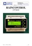
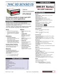
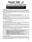
A2X90-VM
Operating Instructions
for
4…20 mA loop powered 96x48 indicator;
Model: A2X90-VM
FT00536-0.00-0179FV A2X90-VM - page 1/12
A2X90-VM
1. Contents
1. Contents ................................................................................................ 2
2. Note ....................................................................................................... 3
3. Instrument Inspection............................................................................. 3
4. Regulation Use ...................................................................................... 3
5. Operating Principle ................................................................................ 4
6. Mechanical Data ……............................................................................ 4
7. Electrical Connection ............................................................................. 5
8. Commissioning ...................................................................................... 7
9. Technical Information............................................................................. 9
10. Order Codes ....................................................................................… 11
11. Dimensions .......................................................................................... 10
FT00536-0.00-0179FV A2X90-VM - page 2/12
A2X90-VM
2. Note
Please read these operating instructions before unpacking and putting the unit
into operation. Follow the instructions precisely as described herein.
The devices are only to be used, maintained and serviced by persons familiar
with these operating instructions and in accordance with local regulations
applying to Health & Safety and prevention of accidents.
When used in machines, the measuring unit should be used only when the
machines fulfil the EWG-machine guidelines.
3. Instrument Inspection
Instruments are inspected before shipping and sent out in perfect condition.
Should damage to a device be visible, we recommend a thorough inspection of
the delivery packaging. In case of damage, please inform your parcel service /
forwarding agent immediately, since they are responsible for damages during
transit.
Scope of delivery:
The standard delivery includes:
•
user's manual (this sheet)
•
warnings
•
96x48 display model: A2X90-VM
•
two fixing clamps
•
removable 12 pole terminal blocks (into the unit)
4. Regulation Use
Any use of the 4…20 mA indicator model: A2X90-VM, which exceeds the
manufacturer’s specification may invalidate its warranty. Therefore any resulting
damage is not the responsibility of the manufacturer. The user assumes all risk
for such usage.
FT00536-0.00-0179FV A2X90-VM - page 3/12
A2X90-VM
5. Operating Principle
The model A2X90-VM 96x48 loop powered display is a universal local display
suitable for use with various transmitters. The transmitter must be fitted with an
analogue output and a terminal blocks.
The display is user programmable. Scaling, the position of the decimal point,
gate time and switch point may be set with two keys. The menu steps are output
to the LED display field.
6. Mechanical Data
The instrument is setted up for panel mounting.
It is fixed in place with the two clamps provided.
The maximum permitted panel thickness is 4mm.
Make all electrical connections with power supply off.
Take care to ensure electrical connections are correct.
Insert the clamps into the button-holes in the right and left sides of the
instrument and put them in tension turning the pin with a screw -driver (slot or
cross, 4 mm).
Make all electrical connections are correct as showed in the schemas below.
FT00536-0.00-0179FV A2X90-VM - page 4/12
A2X90-VM
7. Electrical Connection
Connect the plug-on display as shown in the wiring diagram.
Connector assignment
PIN 1
Switch out
PIN 2
GND
PIN 3
+VS
PIN 4
/
PIN 5
/
PIN 6
/
PIN 7
/
PIN 8
/
PIN 9
/
PIN 10
/
PIN 11
/
PIN 12
/
FT00536-0.00-0179FV A2X90-VM - page 5/12
A2X90-VM
Auxiliary power
The auxiliary power (typically 24 VDC) must be greater than the voltage drop
across the sensor, the voltage drop across the display (5 V) and any other
voltage losses (additional evaluation, cable losses).
Ub = Us + Ua + 5V
(Us = other voltage losses)
Switching output
The operating voltage Ub at PIN 1 is connected through via a PNP-transistor
when reaching the switching threshold. The max. current load constitutes 60
mA.
Connection example A2X90-VM
FT00536-0.00-0179FV A2X90-VM - page 6/12
A2X90-VM
8. Commissioning
8.1 Adjusting the Display
A è Downward and selection of menu items
B è Upward and selection menu items
A+B è Enter menu selection for adjustment or to exit acknowledge setting
8.2 Decimal Point
Press key B until:
d
is displayed.
P
Press A+B to enter adjustment menu:
Press B or A for up and down:
-
-.
-
-
-.
-
-
Press A+B to acknowledge setting and return to menu item “dP”
FT00536-0.00-0179FV A2X90-VM - page 7/12
A2X90-VM
8.3 Zero-Point (value to be displayed for 4 mA)
Press key B until:
I
S
is displayed.
Press A+B to enter adjustment menu:
0.
0
0 for example: (0 bar)
Press B or A for up and down
Press A+B to acknowledge setting and return to menu item “IS”
8.4 Span (value to be displayed for 20 mA)
Press key B until:
F
S
is displayed.
Press A+B to enter adjustment menu:
Press B or A for up and down: 6 0.
0.
0
0
0
0
(for example: 60 bar)
Press A+B to acknowledge setting and return to menu item “FS”
8.5 Damping
Press key B until:
I
n
t
is displayed.
0.
Press A+B to enter adjustment menu:
(min. = 0.3 s; max. = 20.0 s)
Press B or A for up and down:
1.
5
3
(for example: 1,5 sec)
Press A+B to acknowledge setting and return to menu item “Int”
8.6 Range Exceeded
(indication of less than 4 mA or greater than 20 mA)
Indicates “HI” if the upper limit or “LO” if the lower limit is exceeded
Press key B until: I
S
F
S is displayed.
Press A+B to enter adjustment menu:
Press B or A for up and down:
O F
o
n
F
message disabled
message enabled
Press A+B to acknowledge setting and return to menu item “ISFS”
Indication: “HI” = Upper range exceeded, “LO” = Lower range exceeded
FT00536-0.00-0179FV A2X90-VM - page 8/12
A2X90-VM
Attention: When the “HILO” indication is enabled,
error code “HI” or “LO” is displayed if the scale
range (-1999 (LO) to +9999 (HI)) is exceeded.
8.7 Switching Point
Press key B until:
S
E
t
is displayed.
Press A+B to enter adjustment menu:
Press B or A for up and down
2 0.
0. 0
0
0
0
(20 bar)
Press A+B to acknowledge setting and return to menu item “SEt”
Attention: The standard hysteresis is the adjusted
switching point minus 3 digits (first digit resp.
first position right). On customer‘s request the
hysteresis can be factory-set.
8.8 Switching direction
Press key B until:
A
L
L
is displayed.
Press A+B to enter adjustment menu:
(hysteresis via switching point, inverse)
Press B or A for up and down
(hysteresis below switching point)
L
H
I
O
Press A+B to acknowledge setting and return to menu item “ALL”
8.9 Return to Measuring Mode
Depending on the selected menu point, press key A or B from one to eight
times.
9. Technical Information
9. Technical Information
FT00536-0.00-0179FV A2X90-VM - page 9/12
A2X90-VM
Display:
Digit height:
Indicating range:
Accuracy:
Electrical connection:
Sensor supply:
Voltage drop:
Max. current load:
Conversion rate:
Gate time:
Data back-up:
Error message:
Programming:
Protection:
Temperature influence
on display:
Storage temperature:
Ambient temperature:
Case:
Housing material:
Cut-out dimensions:
Depth:
Weight:
Switching output
Open Collector:
Conformity to EWG guidelines:
EMC
LVD
4-digit red LED display,
12,5 mm
Programmable decimal point setting
-1999 to +9999
0.2% of span ± 1 digit
To 2-wire transmitters with 4–20 mA output
12 pole terminal blocks
not required, self -supply loop powered
= 5 V (acc. load: max. 250 )
max. 60 mA
Three measurements/s,
0.3-20 s (adjustable)
Non-volatile FLASH MEMORY
HI: overrange
LO: underflow
With two keys, menu-assisted,
scaling of indication,
decimal point, gate time, error
message switch point
IP 54
0.1% / 10 °C
-30...+80 °C
0...+60 °C
panel mount 96 x 48 mm
Noryl
92 x 45 mm
90 mm (terminal blocks included)
140 g
PNP, max. current load 90 mA
Directive CEE 2004/108
EN 61000-6-4
EN 61000-6-2
Directive: CEE 2006/95
EN61010-1
,
FT00536-0.00-0179FV A2X90-VM - page 10/12
A2X90-VM
10. Order Code
A2X90-VM loop powered 4…20 mA 96x48 indicator
11. Dimensions
FT00536-0.00-0179FV A2X90-VM - page 11/12
A2X90-VM
Document: FT00536 rev. 0.00 of 18/07/2008
Draft:
P. Bruno
Verify:
M. Stillavato
Approvals:
A. Marini
FT00536-0.00-0179FV A2X90-VM - page 12/12