1
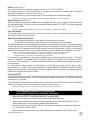
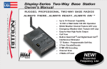
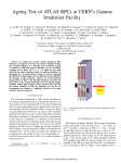
Quick Talk vS TM WIRELESS VEHICLE DETECTION SYSTEM RVS-P1 RITRON VEHICLE SENSOR PROBE INSTALLATION / OPERATION INSTRUCTIONS If the Quick Talk transmitter enclosure is mounted outdoors, you must seal the antenna connection on the radio. Refer to the instructions in the Quick Talk manual, page #13. Use Archer Connector Sealant, Radio Shack #278-1645 or equivalent. Introduction Please read these instructions completely. It is recommended that each system be bench tested prior to installation and that the installer acquaint himself with the Quick Talk vS system. The sensor probe detects the disturbance to the Earths magnetic field caused by moving ferrous metal, such as, steel or iron. The larger the ferrous object and the faster the movement, the further away it will be detected.This system includes the relay board installed inside the Quick Talk enclosure and the vehicle sensor probe.If there are any questions, technical support is available to discuss problems and offer solutions. Earth Ground A proper earth ground of the probe is essential for the systems lightning protection and EMF shielding. Normally, burying the vehicle sensor probe is sufficient to meet the grounding requirements. However, under three conditions the probe must be grounded by attaching it to a separate ground rod: 1) in areas with a poor earth ground;such as, sandy, gravel, or rocky soil; 2) when the probe is inserted in a PVC pipe; or 3) the probe is mounted above ground. To ground the probe, drive an 8 ft copper or copper-clad ground rod completely into the ground (DO NOT USE A GALVANIZED GROUND ROD). Solder and clamp the grounding strap/braid coming out of the vehicle sensor probe to the ground rod. For a proper solder connection, the ground rod must be sanded, fluxed, and heated with a torch until the solder melts onto the rod itself. NOTE: Extra wire may be added to the grounding strap if needed (e.g., if the vehicle sensor probe is located deep inside a PVC pipe). Location of the Vehicle Sensor Probe The sensing range of a probe buried beside the driveway is 5 to 8 ft with a small car going 5 MPH. Taking the width of the car and the sensing range, this system can cover a 12 ft driveway. Buried in the center of the driveway, the system can cover a 24 ft wide driveway...refer to Probe and Cable Installation. The probe should be at least 35 ft back from a street on which traffic is going under 35 MPH and at least 50 ft back from a street on which traffic is going over 35 MPH. If the probe is installed in the center of a 12 ft driveway, it can be 20 or 35 ft back from traffic respectively. This is made possible by adjusting the probes GAIN sensitivity...refer to Adjusting Probe Sensitivity. Stationary ferrous metal near the probe will not hinder its operation. If the probe is used near a moving ferrous metal object, such as a gate, surface tests should be conducted to insure that the object does not accidentally trigger the probe. The probe can be placed into a PVC pipe under an open steel reinforced grid of a concrete roadway without hindering its operation. The probe will not work under a solid piece of steel. Cautions DO NOT bury the gray enclosure containing the Quick Talk transmitter electronics. DO NOT bury the probe within 6 to10 feet of a buried power or telephone line. DO NOT bury the probe within 6 to 10 feet of a buried invisible dog fence. DO NOT bury the probe within 10 feet of a natural gas line. DO NOT bury the probe within 20 feet of a power pole with a transformer. DO NOT bury the probe within 100 feet of railroad traffic. DO NOT bury the probe within 200 feet of sub-station type overhead power lines. DO NOT mount the probe vertically when used for above-ground applications . Probe and Cable Installation Installation tip: Installation of the probe relative to the flow of traffic in the target area is critical. Since one end of the probe has a positive signal and the other end has a negative signal if both ends are activated at the same time they will cancel each other out and the probe will not detect a vehicle in the target area. Therefore, avoid installing the probe where both ends will be activated at the same time; e.g., in a vertical position above ground or perpendicular relative to the flow of traffic in the target area. 1 Typically, the probe is buried 6 to10 inches deep beside, and parallel to the flow of traffic in the target area. It is advisable to bury 6 to 10 ft of extra cable (coiled-up) for future maintenance or relocation. Above Ground Installation When used in an above ground application do not mount the probe vertically. If the probe is incorrectly mounted in a vertical position above ground it is possible to activate both ends of the probe at the same time. Since one end of the probe has a positive signal and the other end has a negative signal they will cancel each other out. Install Parallel or at 450 Relative to Traffic Flow 2 inch PVC pipe 450 Angle Parrallel to Traffic Existing Pavement Installation When installing the probe in existing pavement, bore a 1.5 inch diameter hole vertically, 24 inches deep. Slice the pavement from the bored hole to the driveway edge to accommodate the cable. Install the probe and cable and seal with a suitable material; such as silicone. Dirt / Gravel Installation When installing the probe in a dirt or gravel driveway, first bury a 2 inch schedule 80 PVC pipe in the center of the driveway, 6 to 8 inches deep, and diagonally at a 45o angle...refer to the illustration at right. Then insert the probe and cable in this pipe after it is in place. This prevents damage to the probe/cable from gravel and vehicles. Also, if probe maintenance is necessary, it can be more easily retrieved from the PVC pipe. New Construction Sites When installation is made at new construction sites, install the 2 inch PVC pipe under the driveway as shown in the illustration to the right, pour or asphalt the driveway. Install the vehicle sensor probe and cable in this PVC pipe after landscaping is completed. Top View of Target Area NOTE: If the probe is housed in PVC pipe, the probe itself must be grounded as described in the Earth Ground section. The probe cable is direct burial and does not require conduit. It may be buried underground or kept above ground in a PVC pipe. Depth of burial depends on lawn conditions. In cultured lawn grass, it is sufficient to bury the cable 2 to 3 inches deep. The root system of the grass will capture the wire for life. With a gasoline-powered lawn edger, slice a 1/4 inch wide trench across the lawn to the transmitter. Push the wire to the bottom of the slice, fill and tamp. In uncultured field grass or in soil without cultured grass, bury the cable at least 6 to 8 inches deep. When installing wire through woods and above ground, run it in PVC pipe for mechanical protection, as animals will chew through the cable. Extreme care should be taken when unrolling the probe cable. To unroll, put your arm through the center of the roll of cable, remove the tape, and unravel the roll one wrap at a time. Installing Control Unit All the sensitive electronics have been designed into the sensor probe, making it convenient to mount the relay control board in the same box with the Quick Talk transmitter. Probe Connections (refer to FIG.-1) The standard length of cable that comes with the probe is 80 feet (longer lengths may be special ordered). The length of cable is not critical to performance and may therefore be shortened to any desired length. Before attaching leads to the terminal strip, it is recommended that all leads (probe wire, power leads, ground lead, and relay leads) be solder-tinned. This will insure good contact. Connect the black wire from the probe to the BLK terminal on the relay board terminal strip, the red wire to the RED terminal, and the shield wire to the SH terminal. 2 FIG.-1 Relay Board Probe Connections Power (refer to FIG.-1) The control unit can be operated by a power source from 7.5V DC to 10V DC. The negative terminal (-) on the terminal strip is common connection for the negative side of the power supply and earth ground...refer to Earth Ground. The positive terminal (+) on the terminal strip is for the positive side of the power supply. NOTE: It takes at least 2 minutes after the voltage is applied before the unit can be activated. Relay Output (refer to FIG.-1) The relay output as indicated by COM (common) and NO (normally open) is used to activate the Quick Talk transmitter trigger. The relay time can be adjusted by potentiometer B (TIME). Time can be adjusted from 1/2 to 2 seconds. NOTE: A relay with normally closed contacts is available on a special order basis. Trip-Test Switch The trip-test switch, located center left on the circuit board, is a tool to evaluate the system electronics and to help in setting the time function. Adjust Probe Sensitivity (Gain) · To increase the Sensitivity or Gain, adjust the potentiometer clockwise. · To decrease the Sensitivity or Gain, adjust the potentiometer counter-clockwise. The Gain adjustment of the probe essentially changes the sensing range of the probe. The default sensitivity (Gain) setting is in the 12 oclock (straight-up) position. At this setting the probe will detect a slow moving small car about 5 to 8 feet away when the Gain control is set to the half-way mark. We do not recommend adjusting the Gain beyond the 12 oclock position. Refer to the note below for the exception to this rule: NOTE: The Earths magnetic field is less sensitive in some areas. If the installation happens to be in such an area the Gain setting may need to be increased in order for the probe to function properly or, if possible, relocate the probe several feet. Low sensitivity is desirable when the probe is installed close to highways, power lines, etc. The lowest amount of sensitivity is allowable when the probe is installed in the middle of the driveway...refer to Probe and Cable Installation. Forcing the vehicle to pass over the probe allows the Gain sensitivity to be turned down. To test sensitivity, use a compact or sub-compact car moving very slowly past the probe. Adjust potentiometer A (TIME) fully counter-clockwise and begin adjusting clockwise in small increments. Wait at least one minute to allow sensitivity change to register before re-adjusting. Stop adjusting at the point where the small car trips the system. Test / Fault LED The LED, located at top left of the circuit board, will operate when the test button is activated or the probe is activated by a passing vehicle. The LED will remain on for about one second; the relay will operate for a minimum of 1/2 second. If the LED fails to operate when the trip-test switch is activated or if the LED will not shut off, this indicates a fault in the system; either the relay board or the probe could be at fault. NOTE: If sensitivity is set very low, the trip-test switch will not activate this circuit. Field Installation of the RVS-P1 Control Board into the RQT-150/450 Quick Talk Radio Transmitter * 1. Disconnect the RVS-P1 Control Board from the 3-conductor cable. 2. Remove one side of the protective covering of the double-sided foam tape. 3. Place the exposed adhesive side of the double-sided tape on the bottom of the RVS-P1 Control Board. Make sure to cover the entire underside area of the board. 4. Remove the front cover of the RQT-150/450. The printed circuit board is mounted to the back side `of the front cover. Refer to FIG.-1. 5. Remove the protective covering on the double-sided tape on the bottom of the RVS-P1 board. * RQT single board units only 3 6. Adhere the RVS-P1 board to the back of the Black Wire RQT front cover between the circuit board and the front cover. Refer to FIG.-1. 7. Route the RVS-P1 3-conductor cable through the front of the water tight strain relief on the front of the RQT. The adjustable nut may need to be loosened to do this. 8. Reconnect the 3-conductor cable to the RVS-P1 Control Board. Red wire to RED, black wire to BLK, and shield wire to SH. FIG. - 2 9. Connect one end of the loose black wire to on the RVS-P1 board. Refer to FIG.-2. 10. Solder the other end of the loose black wire in the hole next to J103 (2-pin connector on RQT circuit board) that leads to the black wire on the 6-AA cell battery holder. Refer to FIG.-3. J103 11. Connect one end of the loose red wire to + on the RVS-P1 board. Refer to FIG.-2. Black 12. Solder the other end of the loose red wire in the Wire other hole next to J103 that leads to the red wire on the battery holder. 13. Connect one end of the loose blue wire to COM FIG.- 3 on the RVS-P1 board. 14. Connect the other end of the blue wire to SW1 on the RQT circuit board. Refer to FIG.-4. 15. Connect one end of the loose white wire to NO White on the RVS-P1 board. Refer to FIG.-2. Wire 16. Connect the other end of the white wire to + SW1 on the RQT circuit board. Refer to FIG.-4. Blue 17. Re-attach RQT front cover to back cover. Wire 18. Tighten the adjustable nut on the water tight strain relief. Refer to FIG.-5. FIG. - 1 RVS-P1 circuit board Red Wire Blue Wire White Wire Red Wire FIG. - 4 Sensitivity (Gain) Adj. Time Adj. FIG. - 5 Proper Procedure to Repair a Cut or Damaged Probe Cable Follow this procedure if the black cable provided with the probe is damaged or cut. Two items will be necessary when splicing: 4 · Two-wire shielded direct burial cable (unshielded cable and PVC jacketed cable will not give proper splices). · Underground splice kit (made by 3M, Part #82-A1) Note: Lightning can cause the probe to false if the strike is large enough and within 1-mile of the probe. A well-grounded probe will minimize false activation of the probe. FIG.-A: Strip the outer jacket on one cable back 10 inches and cut the red and black leads to 3 inches, leaving the shield drain wire the full 10 inch length. Strip the outer jacket off the mating cable back 3 inches and strip the jacket of the red and black lead of both cables back 1/2 inch. Twist the black to black and red to red and solder the connections as shown. FIG.-B: Trim the red and black joints and tape for proper insulation. Twist the 3 inch shield drain wire to the 10 inch shield drain wire and solder the connection as shown. FIG.-C: Wrap aluminum foil around the splice area. Wrap the 10 inch shield drain wire tightly around the outside of the foil and solder it to itself in order to hold it in place, as shown. This procedure insures that any signal to the splice shield will drain to ground and thus prevent false alarms. FIG.-D: Place an underground splice kit potting container around the spliced cable and epoxy pot. 5 Vehicle Probe Technical Specifications Designation: Power Source: Current Drain: Standby: Tripped: Relay Time: Relay Rating: Re-trigger Hold-off: Temperature Range: RVS-P1 Vehicle Sensor Probe 7.5 - 10 VDC < 60 micro-Amps 50 mA 1/2 to 2 seconds Single pole, single throw normally opens contacts 1 Amp @ 24 VDC (1 mA @ 5 VDC min. load) 10 seconds - 250 F to + 1500 F (- 320 C to + 750 C) Quick Talk Transmitter Specifications Designation: Typical Range: Battery Life: Antenna Connector: Enclosure: Dimensions: Weight: Switch Inputs: Coded Signalling Encoder: Jumper Selectable: Message Length: Auxiliary Messages: Message Scheduling: Programming Method: RQT-150 VHF RQT-450 UHF Using standard antenna supplied with RQT; 1/2-mile to a portable radio line-of-sight 1-mile to the Ritron base station line-of-sight. Increased range is possible using a gain antenna on the RQT or a radio repeater. 1 year when using AA Alkaline batteries or 7,000 transmissions. BNC, 50 Ohms GE-Noryl, Grey, Ultraviolet Stable, NEMA-4-4X Water Resistant with 4 Mounting Ears. 5.25 X 5.25 X 2.5 1 lb less batteries and antenna 2 Momentary, Latching, Analog, or Resistance. CTCSS, Quiet Call, 51 Tones DCS, Digital Quiet Call, all codes. Wide (25 kHz or Narrow (12.5 kHz) band deviation Compressed Transmit Audio (for use with radios using companded technology) 8 seconds per switch condition when 1 switch input is used. 3.25 seconds per switch condition when 2 switch inputs are used. Plus a 3.25 second location message. Low Battery Alert (1.5 seconds) External Power Failure (1.5 Seconds) User programmable intervals and repeat times User programmable with a standard pulse dial telephone. Note: Special office telephones, speaker telephones, and telephones with lighted dials cannot be used to program the Quick Talk. More Wireless Solutions from Ritron Since 1977 Ritron has been designing, manufacturing, and supplying professional wireless communication systems and products worldwide. Base Station/ Wireless Intercom The Jobcom Base Station/Wireless Intercom and OutPost 2-way Callbox are ideal add-ons to any existing radio system that provide cost-effective wireless communication solutions to any location. 505 W. Carmel Drive · Carmel, IN 46032 Ph: 317-846-1201 · FX: 317-846-4978 · Email: [email protected] Web site: www.ritron.com 6 OutPost 2-Way Callbox P/N: 14500037 Rev B 10-03