1
EPMedSystems
EP-WorkMate®
User's Guide
EP MedSystems, Inc.
100 Stierli Court, Ste. 107
Mount Arlington, New Jersey 07856
U.S.A.
973-398-2800
Copyright © 1996-2000.
All Rights Reserved.
Part # 04-0002-0000 Rev. I
Software Version 2.11.5
000001
2/7/00
SJM03074942
ST. JUDE MEDICAL 1121
000002
000002
SJMO3O74943
SJM03074943
I
I
Warrant
Limited
Warranty
EP MedSystems, Inc. ("EP Med") warrants, subject to the
exceptions and upon the conditions specified below, that the
"Product" will be free of defects in materials and
workmanship for a period of one (1) year from the date of
shipment to the original purchaser; provided however, that
the warranty with respect to all cables and other connective
devices provided with the Product shall be for a period of
ninety (90) days only.
In the event EP Med receives
notification of any such defects during the warranty period,
EP Med shall, at its option and expense, either repair or
replace defective components or parts of the Product which
in the sole and reasonable judgement of EP Med is defective
by reason of material or workmanship. In no event shall EP
Med be required to repair or replace any Product or any
portion thereof with respect to any defect, regardless of the
cause of such a defect, if the Product was not used in a
normal and proper manner in accordance with the use and
specification guidelines provided by EP Med. The warranty
provided herein is limited solely to the original purchaser of
the Product.
Obtaining
Warranty
Service
To obtain warranty service, the customer must contact EP
Med (1-800-361-6464) for an initial assessment of the
problem. The EP Med customer service department shall
assign a Return Authorization Number to the Product and
instruct the customer as to its return. The customer shall
be responsible for all charges incurred in shipping the
product to EP Med and shall insure and accept all liability
for loss or damage to the Product during shipment. In the
event EP Med determines that the Product or component
thereof is covered by the warranty described above, EP Med
shall pay for the return of the product to the customer.
Otherwise, the item will be returned to the customer with
transportation charges collect. The customer shall pay all
shipping charges, duties, and taxes for products returned to
EP Med from a country other than the United States.
All returns should be shipped to the following address:
000003
SJM03074944
EP MedSystems
100 Stierli Ct. Suite 107
Mt. Arlington, New Jersey 07856
Optional
Extended
Warranty
The customer may choose to purchase an extended
warranty at any time during the warranty period. This
extended warranty extends the warranty period described
above for a period of one (1) year coverage of service for the
Product only to begin with the end of the initial warranty
period.
Exclusions
In addition to the exclusions described above, EP Med shall
be released from all obligations under its warranty if repairs
or modifications are made to the Product by persons other
than EP Med's own or authorized service personnel.
EP Med shall be released from all obligations under its
warranty for defects resulting from improper assembly of the
Product or the operation of the Product outside of the
environmental, electrical, and other Product specifications.
EP Med shall be released from all obligations under this
warranty in the event the Product or component thereof is
used by anyone other than a board certified cardiologist or a
qualified electrophysiologist.
The warranty provided herein is the sole and exclusive
warranty with respect to the Product. No representations or
warranties made by any person, including dealers,
employees and other representatives of EP Med shall be of
no effect whatsoever unless approved by a duly authorized
officer of EP Med.
Product
Return
Policy
EP MedSystems will accept for return all products which are
(1) shipped in error by EP MedSystems; (2) returned at the
request of EP MedSystems or (3) held by customers for more
than thirty (30) days. In obtaining credit, all merchandise
must be returned postage pre-paid and in good, unopened
condition. Credit will be provided by EP MedSystems for all
products conforming to the foregoing as follows:
Full credit will be issued for all merchandise described in (1)
and (3) above. Credit less than 20% restocking charge will
be given for the merchandise described in (3) above. All
credits will be directed adopted from original invoice and
reflected as a credit amount.
In order to obtain credit for returns customers should call
000004
SJM03074945
EP MedSystems Customer Service Department at 1-800361-6464 to receive authorization to return the product.
When returning the product the customer must provide (1)
return goods authorization number which was obtained
from customer service; (2) the purchase order and EP
MedSystems invoice number; (3) the quantity, lot number or
serial number of each item being returned and (4) written
description of the reasons for returning the product. All
returns must be shipped postage pre-paid in EP
MedSystems's
original
protective
package
to
EP
MedSystems, 100 Stierli Ct. Suite 107, Mt. Arlington, New
Jersey, 07856.
No credit will be given for any merchandise which is
returned without strict compliance with the foregoing or for
any product which is opened, damaged or otherwise used by
the customer. Except for merchandise shipped in error or
recalled by EP MedSystems, the customer is responsible for
all shipping and insurance charges.
Disclaimer
of
Warranties
EP MEDSYSTEMS MAKES NO OTHER WARRANTY, EITHER
EXPRESSED OR IMPLIED, WITH RESPECT TO THE PRODUCTS. EP
MEDYSTEMS SPECIFICALLY DISCLAIMS ANY IMPLIED WARRANTIES
OR MERCHANTABILITY AND FITNESS FOR A PARTICULAR PURPOSE.
IF THIS PRODUCT DOES NOT PERFORM AS WARRANTIED HEREIN,
PURCHASER'S SOLE REMEDY SHALL BE REPAIR OR REPLACEMENT,
AT EP MEDSYSTEMS OPTION, AS PROVIDED ABOVE. IN NO EVENT
WILL EP MEDSYSTEMS BE LIABLE FOR DAMAGES, LOST REVENUE,
OR ANY OTHER INCIDENTAL OR CONSEQUENTIAL DAMAGES
ARISING FROM THE PURCHASE, USE, OR INABILITY TO USE THIS
PRODUCT, WHETHER BASED ON CONTRACT, TORT OR OTHER
LEGAL THEORY.
EP MEDSYSTEMS DISCLAIMS LIABILITY FOR
PERSONAL INJURY, DEATH OR PROPERTY DAMAGE OCCURRING IN
CONNECTION WITH THE USE OF THE PRODUCT BY ANYONE OTHER
THAN A BOARD CERTIFIED CARDIOLOGIST OR QUALIFIED
ELECTROPHYSIOLOGIST. ANY USE OF THE PRODUCT CONSTITUTES
AN AGREEMENT BY PURCHASERS AND ALL USERS TO INDEMNIFY
AND HOLD HARMLESS
EP MEDSYSTEMS, INC., ITS OFFICERS,
DIRECTORS, EMPLOYEES AND AGENT FROM ANY AND ALL CLAIMS,
SUITS, COSTS, JUDGEMENTS AND REASONABLE LEGAL FEES
ARISING FROM PERSONAL INJURY, DEATH OR PROPERTY DAMAGE
OCCURRING IN CONNECTION WITH THE USE OF THE PRODUCT BY
ANYONE OTHER THAN QUALIFIED PERSONNEL AS DESCRIBED
ABOVE.
This agreement is SUbject to and is governed by the laws of
the State of New Jersey. Any action brought in respect of
the Product shall be brought in the State of New Jersey.
The purchaser and all parties seeking claims in respect of
the Product attorn to the jurisdiction of the State of New
Jersey.
000005
SJM03074946
EPMedSystems, Inc.
New Jersey, U.S.A.
000006
SJM03074947
11--Table of Contents
l!711rrlllltJr
i
Tllble of COlltellts
v
Figures
viii
About this MllIlUlll
ix
Manual Overview
Vital Information
Definitions, Acronyms and Abbreviations
ix
xi
xi
Illtroductioll
1
Functional Description
Operating the EP-WorkMate
EP-WorkMate 24
Patient Connections
User Interface
Cautions and Disclaimers
Turning Off the EP-WorkMate
The Millennium
:
User Illterfilce
2
5
5
5
6
7
8
8
9
The EP-WorkMate Main Menu (Shell)
The EP-WorkMate Screens
Hot Keys
Gettillg Stllrted
11
15
15
19
Power On
User Interface
The Basics of Electrophysiology Studies
Operation Overview
Review Screell
19
19
20
24
27
Real-time Monitor Controls
Review Scrolling Controls
Changing the Real-time or Stored Electrograms
000007
34
35
37
SJM03074948
Signal Intensity
Marking Events
Annotation Font Size
The Split Window
The Holter Window
The Stimulator Window
4 Pacing Sites from 2 Pacing Channels
The RF Window
The Cine Window
The LOG Window
Strip Chart Recorder (Optional)
Setup Screen
39
39
39
39
40
41
44
44
46
47
48
51
What is a CathMap?
Setup Screen Controls
Define Setup Channels
Changing Real-time Signal Attributes
Signal Intensity
Invasive Pressure Monitoring
Save CathMap Changes Prompt
Database Screen
51
52
54
57
58
58
59
61
FAX Utility
63
Advanced Techniques
Bipolar vs. Unipolar Signals
Sample Rate and Filtering
Integrated Pressure
Synchronizing Stimulus to the ECG
Query Utility
65
65
65
66
67
69
Advanced Query Options
Performing a Query - Tutorial
Exporting Patient Demographics
Installation and Assembly
Assembling the Cart
The EP-WorkMate Main Computer
EP-3 Stimulator
The EP-WorkMate Signal Conditioning Unit (SCU)
The Pressure/Marker Interface (PMI)
ECG Sync Output
The EP-WorkMate Catheter Interface Box (CIB)
Power
Cine Capture
Turning on the EP-WorkMate-Preliminary test..
000008
71
72
72
75
75
76
78
80
82
83
83
84
84
85
SJM03074949
System Configuration
EPWM.INI File
SHELL.INI File
TIGA Board Configuration
CONFIG.SYS File
AUTOEXEC.BAT File
Error Files
Signal Conditioning Unit Configuration
SCU Beep Sequence
24 Channel SCU
56 Channel SCU
120 Channel SCU
Cine Capture Board
Reporting
87
87
95
96
98
98
98
99
99
100
100
10 1
101
103
Report Menu
Report Editor
103
105
Exporting Data
113
Exporting Signals
Export File Names
Export Channel File Fonnats
Exporting Patient Demographics
113
113
114
115
Troubleshooting Guide
117
Stimulation
Pressure
Displays
Signals
Analysis
RF
Measurements
Setup Screen
Optical Disks
Technical Support
117
118
118
120
123
124
124
124
125
125
Maintenance
127
Component Maintenance
Recommended Backup Strategies
Software Upgrade Installation
127
128
128
Specifications
129
Index
131
000009
SJM03074950
Fi ures
Figure 1. The EP-WorkMate Cart and Components
3
Figure 2. Basic EP Lab Connections
4
Figure 3a. The EP-WorkMate Main Computer (older)
76
Figure 3b. The EP-WorkMate Main Computer (newer)
77
Figure 4. The EP-3 Stimulator..
79
Figure Sa. The EP-WorkMate 72 Channel Signal Conditioning
Unit wlo Pressure
81
Figure Sb. The EP-WorkMate 140 Channel Signal Conditioning
Unit with Pressure
82
Figure Sc. The EP-WorkMate 44 and 76 Channel Signal
Conditioning Unit with Pressure
82
Figure 6. The EP-WorkMate Catheter Interface Box
83
Figure 7. Power diagram for the EP-WorkMate
84
000010
SJM03074951
11--About this Manual
This manual is intended to help you get the most out of your
EP-WorkMate® computerized EP system. Although you will
find the EP-WorkMate easy to use, we strongly recommend
that you read chapters 1 through 6 before you begin to use
the product clinically. These chapters contain important
information basic to the safe operation of the system as well
as some time saving tips that will allow you to use the full
power of the EP-WorkMate.
For information on the operation and specifications of the
EP-3 stimulator, please refer to the EP-3 stimulator manual
provided with the system. We strongly recommend you read
the tutorial chapter before you use the product clinically.
Manual Overview
Here is an introduction into the manual's organization.
Chapter 1
Introduction
This is an introduction chapter to the EP-WorkMate. It
describes the various components that make up the EPWorkMate.
Chnpter 2
User Interface
This chapter introduces the user interface of the EPWorkMate.
Chapter 3
Getting Started
This chapter gets you started using the device and includes
a tutorial on using the EP-WorkMate. This tutorial covers
the basic skills needed to operate the EP-WorkMate.
Chapter 4
Review Screen
This reference chapter describes the Review Screen
including the purpose and function of each menu and key.
This includes stimulation and cine functions.
ChapterS
Setup Screen
This reference chapter describes the Setup Screen including
the purpose and function of each menu and key. The Setup
screen defines all signals and viewed protocols.
This
000011
SJM03074952
includes instructions in changing the real-time monitor.
Chapter 6
Database Screen
This reference chapter describes the Database Screen
including the purpose and function of each menu and key.
The database is a key feature of this device controlling signal
review, query, reporting and archiving of stored signals. The
FAX utility is explained as well.
Chapter 7
Advanced
Techniques
This chapter explains advanced concepts including unipolar
signal recording, filter theory, pressure waveforms and
measurements, stimulator ECG syncronization, and others.
This is meant to be read after previous chapters and the EP3 user's manual are read.
ChapterS
Query Utility
This chapter explains the query utility. The query is a
useful tool to search all patient data. A demo tutorial is
included for practice.
Chapter 9
Installation and
Assembly
This chapter is a description of the components and
assembly of the EP-WorkMate. It is intended for bio-medical
engineers and EPMedSystems personnel. It is also useful
for device re-assembly after moves.
Chapter 10
System
Configuration
This chapter is a technical description of software and
hardware configuration settings. It is intended for biomedical engineers and EPMedSystems personnel. It is also
useful in troubleshooting performance problems.
Chapter 11
Reporting
This chapter describes the report templates and functional
use of the report editor. The report editor is useful for
customizing reports generated by the EP-WorkMate.
Chapter 12
Exporting Data
This chapter describes signal and data export capabilities of
the EP-WorkMate. Data can be exported via DOS files with
each signal contained in a separate file at the sample
frequency.
Chapter 13
Troubleshooting
Guide
This chapter describes troubleshooting techniques. Answers
to many common questions and problems are included.
Please review this chapter when in need of technical
support.
Chapter 14
Maintenance
This chapter describes required maintenance of the EPWorkMate.
It describes preventative maintenance
procedures for the product.
Appendix A
Specifications
This appendix contains technical specifications of the EPWorkMate.
000012
SJM03074953
Vital Information
Throughout this manual critical information will be set off
from the rest of the text in the following ways:
IMPORTANT
III
Text set off in this manner and with a tag in the margin
presents important information. Information that is vital to
the proficient use of the system is labeled as Important.
..
WARNING
A warning indicates information which is related to patient
or operator safety, or possible damage to the equipment.
Throughout the manual references to particular keys on the
computer display and keyboard will shown in BOLD type.
Definitions, Acron ms and Abbreviations
EP
EP-3
SCU
PMI
CIS
DOS
AjD
DjA
Selecting
Electrophysiology
An EP stimulator
Signal Conditioning Unit (Amplifier)
PressurejMarkerInterface
Catheter Interface Box
Disk Operating System
Analog to Digital Converter
Digital to Analog Converter
Clicking the left mouse button once while the
mouse pointer is pointing to a selectable item.
000013
SJM03074954
This page is left intentionally blank.
000014
SJM03074955
CHAPTER
111
_
Introduction
EP-WorkMate is a fully computerized system for capturing
and measuring physiological data in the clinical
electrophysiology laboratory. It provides digital signal
acquisition and display of those electrical signals on high
resolution monitors.
An Electrophysiology system is used to monitor and analyze
surface ECGs and intra-cardiac signals. Catheters are
guided into the heart and intra-cardiac electrical signals are
acquired from the electrodes on the indwelling catheters
from various heart locations. These signals are then used to
measure irregular cardiac electrical activity that may occur
in the heart. A cardiac stimulator is used to send an
electrical pulse via a catheter to the heart. These electrical
pulses are called pacing protocols. Pacing protocols are
performed in order to reproduce any life threatening
arrhythmias under the safest possible conditions for the
patient. Treatment of an arrhythmia is then initiated with
radio frequency ablations, drug therapy, or placement of
cardiac devices that will control the heart's rhythm.
The system is also intended for recording electrocardiograms
from multiple sites during clinical assessment of
electrophysiological
interventions.
The
EP-WorkMate
provides on-line measurements of intra-channel intervals,
and presents these measurements on the display monitor.
Retrieval and display are provided without interruption of
the multi-channel acquisition process. An optical disk drive
(MOl or digital audio tape (DAT) is used for archival storage
of digitized data.
The standard hardware configuration consists of three 21"
high resolution display monitors, a Pentium ™ processor, 2
Gbyte hard disk drive, 1.44 Mbyte floppy disk drive (3.5"),
2.6- 5.2 Gbyte Optical (MO) drive or 4 Gbyte Digital Audio Tape
(DAT) tape drive, TI 34020 Advanced Graphics Coprocessor,
76 channel analog-to-digital (A/D) signal conditioning data
acquisition module (56 intra-cardiac) with integrated
pressure/ marker interface, catheter interface box, EP-3
000015
SJM03074956
integrated stimulator, and HP LaserJet 6 series printer.
Available options include: 24 intra-cardiac cOOnnel signal
conditioning unit (44 total), 120 intra-cardiac cOOnnel signal
conditioning unit (140 total), 32 cOOnnel strip cOOrt recorder,
cine capture, and additional slave monitors.
Menu driven software is incorporated for data acquisition,
analysis, interval posting, instant retrieval with waveform
markers and intervals displayed, marker editing capability,
and personal form generation. EP-WorkMate has an
integrated patient data base system for rapid access to all
patient records. Unique features of the system include: Online interval measurement, two channel integrated
stimulator, a choice of scrolling or wiper-mode display
during real-time signal acquisition, a comprehensive
database with a query function, integrated RF graphics, and
a user configured report editor with fax capabilities.
Functional Descri tion
EP-WorkMate is a computer based electrocardiographic
recording and monitoring system designed for efficient
capture, display and retrieval of surface and intra-cardiac
signals during cardiac electrophysiology studies. The system
contains a fully automated software waveform detector
(trigger) which performs on-line recognition of cardiac
activation on pre-selected leads.
Temporal interval
measurements are computed on a beat-by-beat basis on
multiple channels and dynamically posted on the real-time
display. Intervals are calculated between waveforms from
the same source on a specific channel (intra-channel
measurements), and from multi-source signals across two or
more channels (inter-channel measurements).
All trigger locations, with notes or annotations, as well as
interval measurements are stored concurrently with the
digitized signals. The following intervals are presented on
the display monitor as they occur: atrial-to-atrial (AA),
ventricular-to-ventricular (VV), surface QRS-to-QRS (RR),
ventricular-to-atrial
(VA),
atrial-to-His
(AH),
His-toventricular (HV), and ventricular-to-atrial (VA). Continuous
capture of the digitized signals can be invoked for any
portion of the study protocol, or for the entire study.
Retrieval of earlier passages of the current study, or an
earlier study of the same patient, can be enabled on a
secondary monitor without interruption of the real-time
display. Review by protocol or by time of event can be
invoked by use of user interface buttons and hot keys.
Editing of computer-generated trigger markers can be done
000016
SJM03074957
under operator control in the retrieval mode. Archival
storage of edited patient records is provided on large optical
disks or digital audio tape.
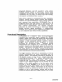
Figure 1 is a picture of the El'-WorkMate Cart and its
components.
Figure J. TheEP-WorkMate Cart and Components.
000017
SJM03074958
WARNlNG
The cart pictured in figure 1 is mounted on wheels and is
portable. During operation it is important to set the front
wheel locks to prevent unexpected movement. Failure to do
$0 could result in possible daI11age to th~ equipment and/or
disruption of desired operation.
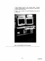
Figure 2 is a block diagraI11 of most EP recording systems in
use today. The cardiac signals are monitored by viewing a
real time monitor,and are analyzed by viewing and
measuring these signals on the review monitor. The cardiac
signals are captured and conditioned with a signal
conditioning unit, and then stored by the computer. The
stimulator sends electrical impulses to indwelling catheters
through the signal conditioning unit. The computer then
sends the signals to the monitors and stores these signals
for future retrieval. Significant events and. user notes are
also stored for each electrophysiology procedure.
Electrophysiology summary reports and electrograms can be
printed as desired.
[
Real-th'ne
Monitor
] [
Review
Monitor
]
P,. . .""
Calh-elen.
!JU",IiOh
80'
l--
I
CPU
AmPlifier,
12 Leild ECG
-1sumlilato-r
Figu~
~
I
Printer
I
2. Basic EP Lab Connections
000018
SJM03074959
the EP-WorkMate
Turning on the main power switch located between the
monitors will power the entire cart provided the isolation
transformer is plugged into an electrical outlet.
IT]
IMPORTANT
The EP-3 stimulator is powered by a battery and only charges
when it is OFF. Care must be taken to ensure the EP-3 is
charging after the cart is turned off by verifying the charging light
is lit.
EP-WorkMate 24
Most of this manual describes the EP-WorkMate
configuration with a review monitor, a slave monitor and at
least a 56 channel signal conditioning unit.
The EP-WorkMate 24 has only one monitor so all mentions of
independent review and real-time monitors are not
applicable. Use the split screen buttons such as Split, RF,
Holter, and Monitor to control the real-time and review
portions of the monitor.
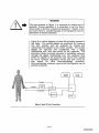
Patient Connections
The patient is connected to the EP-WorkMate through a
surface ECG cable, catheters and pressure transducers.
These are plugged into the amplifier and the catheter
junction box. These inputs are electrically isolated from
earth ground. The stimulator is electrically isolated as well
and is plugged into the amplifier.
Non-isolated
inputs
are
available
through
the
pressure/marker interface. Analog signals from other devices
may be displayed using the non-isolated channels. Marker
channels or pressure signals from isolated pressure
amplifiers can be displayed from these inputs.
000019
SJM03074960
IMPORTANT
Special attention must be given to proper grounding and
electrical safety. Even small chassis leakage currents
passing through the heart can induce fibrillation. Never
connect non-isolated inputs or outputs directly to a patient.
A functioning defibrillator should always be available.
WARNING
The
stimulator back panel connectors and the
pressure/marker interface box are NOT isolated. Never
connect them directly to a patient. Always plug external
devices into an isolation transformer.
User Interface
EP-WorkMate consists of two independent 21 inch, high
resolution screens as well as a keyboard and a mouse for
control of data acquisition, storage, and retrieval of
electrophysiological signals. The main monitor is dedicated
to real-time visualization of signals. Signals which can be
accommodated are typically surface ECG, intra-cardiac
signals, stimulation markers, and output of blood pressure
transducers. Automated wave form recognition and interval
measurement
are
available
for
any
of
the
electrocardiographic signals. The page number is also
displayed.
The secondary monitor is used as a menu-driven review
console for display and retrieval of data from either the
current study or a previous study contained in the patient
data base.
The presentation of menus provides for selection and control
of system features. These features may be either mouse or
keyboard activated and include such options as:
•
Catheter or lead identification,
•
Choice of location, size, and color of the signal display,
•
Selection of signals to be automatically analyzed,
000020
SJM03074961
•
Entry of customized study protocols,
•
Enabling or disabling permanent storage of signals and
measurements onto system storage media.
The review monitor serves as the display medium for
previously recorded data. In the Review screen, any portion
of the recorded file can be accessed by event marker, time of
event, or by scrolling through in a continuous or page-bypage mode. Other options available in the Review screen are
a Holter screen, zoom capabilities, post acquisition filtering,
and automatic analysis.
Cautions and Disclaimers
EP-WorkMate detection algorithms contain a sophisticated
software trigger for electrocardiograms. However, the
accuracy of trigger placement and interval measurement
cannot be guaranteed, particularly in the case of poor signal
quality. Therefore, verification of trigger locations and
associated measurements is required on the part of the user
before full confidence can be placed in reports produced by
EP-WorkMate's automated analysis.
The equipment is intended for use by qualified. medical
personnel and only after they have been trained in the
proper use of this equipment.
EPMedSystems, Inc. does NOT assume responsibility for
damage to the equipment caused by improper ventilation,
improper or faulty power, or improper monitor booms.
For continued safety, it is necessary that the instructions
listed in this manual are followed. It is important that
instructions in this manual in no way supersede established
medical procedures concerning patient care.
Federal law restricts this device to sale by or on the order of
a physician.
.
WARNING
EXPLOSION HAZARD. Do not use this equipment in the
presence of flammable anesthestic.
000021
SJM03074962
WARNING
Installing un-approved software or operating system on the
EP-WorkMate hard drive may severely affect system
performance and device safety.
Turnin OfT the EP-WorkMate
Exit the software to the main menu using the user interface
navigation techniques presented in the following sections.
Always remember to return the main stimulation menu
before turning off the EP-3 to save changed protocols.
WARNING
EXIT THE SYSTEM VIA THE MENU-DRIVEN SELECfIONS
BEFORE TURNING THE POWER OFF. Advanced buffering
techniques are used for both the database and real-time
acquisition. Simply turning off the system or a power failure
while running the system could cause loss of data.
The Millennium
The EP-WorkMate and EP-3 stimulator are fully compliant
with year 2000 requirements. For all database fields in the
EP-WorkMate, the century is stored with all dates. February
29, 2000 is recognized as a leap year, and all date
calculations such as patient age utilize the century allowing
the age to be more than lOO years.
000022
SJM03074963
CHAPTER
121
_
User Interface
The user interface consists of two monitors performing
separate tasks controlled by a single mouse/trackball. Each
monitors' interface is defined in detail in sections below.
Mouse Control
The mouse/trackball controls a mouse pointer that moves
around on the screen as the user moves its' controlling
device. It will also move from monitor to monitor. The
mouse pointer will partially disappear on one monitor as it
appears on the other. The orientation of the monitors is
important. If the real-time monitor is left of the review,
moving the mouse to the left on the real-time will not wrap
around to the review monitor. Of course moving it to the
right will move from the right edge of the real-time to the left
edge of the review. If the monitors are reversed, the opposite
will happen.
The left mouse button always selects the item that the
mouse pointer is pointing to.
It is used to select menu
items, buttons, move annotations, store intervals to the
database, edit signal attributes, move review screen traces,
edit database fields and a variety of similar functions.
The middle mouse button is used to change the attributes of
the item the mouse pointer is pointing to. It is used to edit
annotations, mark log entries, move calipers and similar
functions. When the mouse pointer is not pointing to an
editable item, it invokes the previously invoked caliper in the
review screen. Thus pressing the middle mouse button in
the review signal area when not pointing to an annotation or
caliper interval will pop-up a caliper.
The right mouse button is used to remove any currently
viewed menu or text input box. Thus the right mouse
button returns to the previous level of menus.
000023
SJM03074964
Buttons
Each major task or control feature is implemented by a
button. Clicking the left mouse button on one of these
control buttons performs its function. When the buttons
are not accessible, they are either removed from the screen
or tum a different color.
One of the letters of most buttons are a different color than
the others. Pressing that letter or Alt-Ietter will invoke the
button function.
Menus
Menus may appear when a button is selected. Menus
display lists of options when appropriate. The right hand
side of all menus contains a scroll bar allowing the user to
move through the list of options quickly. One of the these
options within the main menu is always highlighted. The
highlighted option can be changed by selecting the Up
Arrow and Down Arrow buttons above and below the scroll
bar, respectively. These buttons can also be used to view
options not listed currently on the screen.
Pressing the left mouse button when the cursor is over one
of the options will place a check mark to the right of that
option. Pressing the right mouse button or striking the
Return key will enter that option into the appropriate
position on the monitor.
Pressing the right mouse button will always remove any
menu from the screen.
When any menu is displayed simply typing the desired
option will highlight that option if it has been previously
defined.
Selecting the EDIT button at the bottom of all menus will
display the menu editor. The menu editor allows the user to
insert new and delete unwanted menu options. These
options are listed in two columns, the left column is labeled
'Menu Used for Screens' and the right column is labeled
'Menu Used for Forms.' 'Menu Used for Screens' entries will
be displayed on the menus within the EP-WorkMate
screens. When any of these menu selections are printed
onto reports, their corresponding entry in 'Menu Used for
Forms' will be printed.
Selecting the INS(Insert) will prompt the user to type in the
new menu item. That item is stored by pressing Return.
Selecting DEL (Delete) to delete the highlighted choice.
000024
SJM03074965
Yes/No Inputs
A Yes/No Input Box is displayed when a selected function
may result in unwanted results (e.g. when deleting a
patient's data from the memory). A question is displayed
within the box along with two buttons labeled 'Yes' and 'No.'
Most questions are worded so that 'Yes' is the desired
response. Striking the Return key will always answer 'Yes.'
Text Inputs
A Text Input Box allows the user to enter free form text into
the selected area. Striking the Return key or pressing the
right mouse button will enter the input.
On the EP-3 keyboard there is both a Return key and a
Enter key. Use the Enter key to insert a carriage return or
new paragraph into a comment. On a normal PC keyboard
the right Ctrl key performs the same function.
The main purpose of the keyboard is to control the EP-3
stimulator. However, all alphanumeric keys can be used to
select buttons or functions and enter data. All function
keys and the keys on the right side of the keyboard control
EP-3 functions.
Keyboard
..
WARNING
Care should be taken to avoid spillage of liquid onto the
keyboard.
This could cause the keyboard to become
inoperable during operation. Use a plastic shield if there is a
chance of this happening in your environment.
The EP-WorkMate Main Menu Shell
Introduction
The Main menu appears when the computer is turned on. To
initiate an option select the appropriate label by pressing
the left mouse button.
Begin/ Review
Study
Selecting this option will initiate the EP-WorkMate software.
This is the choice you will select the majority of the time.
Archive Log
Files
Selecting this option displays the Archive Log Files Utility.
This utility allows previously recorded patients to be stored
to either a 2.6-4.8 Giga-byte optical disk (MO) or a 4.0 Gbyte
Digital Audio Tape (OAT).
Before selecting this option, place an optical disk or digital
tape into the correct drive. The EP-WorkMate will prompt
the user to name the disk if it already has not been
previously named and will automatically calculate the free
000025
SJM03074966
disk space available. Patients' data that will fit onto the
disk will have a check mark to the right of their names.
Striking the Menu/Esc key or pressing the right mouse
button will begin the downloading process after
confirmation. The Main Menu will reappear when the
process is complete.
Restore Log
Files
Selecting this option will load a patient from the OAT to the
EP-WorkMate's hard drive (cases cannot be reviewed from
the OAT).
NOTE: This is only for those systems with OAT storage
capabilities.
Before selecting this choice, place the digital tape into the
digital tape drive. The EP-WorkMate will initially ask if the
user desires to restore all of the patient's on the tape. If 'NO'
is selected then the EP-WorkMate will prompt the user to
select the patient's desired to be restored. Type the patient
name or press Return/Enter for a list of patients on the EPWorkMate. If the patient has more than one procedure,
select the ones to be restored. The system will then restore
the files to the EP-WorkMate log files. If the patient has
been deleted from the database, use catalog below to find
the patient on the tape.
Restoring the files will take a few minutes. The EPWorkMate Main Menu will appear when the files have been
restored.
Catalog Tape
Before selecting this choice, place the digital tape into the
digital tape drive. After selecting this option the patients
that have been stored on the OAT will be listed on the
screen. Striking the Return key on a specific patient will
restore that patient to the hard drive and database. If it
asks you to restore additional patients, press N.
Edit Menus
Selecting this option will allow the user to print, edit, or view
all of the user definable menus (e.g. catheters, events, etc...)
used by the EP-WorkMate.
The Menu Editor screen will display Edit/View Menus or to
Print Menus. Print Menus will print a list of all menus
available
To edit or view a selected menu, first select the menu. The
selected menu will then display two different categories:
MENU USED FOR SCREENS are the screen menus used
000026
SJM03074967
with the EP-WorkMate.
MENU USED FOR FORMS displays the way that menu
choices will be presented in study reports. Thus on the
screen the data can be shown in an abbreviated form and on
the report the data can be printed in an expanded way (in
sentence form for example).
To edit a menu category or insert a new menu entry, select
Edit/View Menus. Then select the menu title you want to
edit. To insert a new menu entry, select INS for insert. The
new entry will be inserted above the screen bar cursor in the
menu screen. To edit a menu category, select the entry with
the mouse or screen bar cursor and a free text screen allows
you to change or modify the name. To enter, click the right
button, or press Return/Enter.
To delete a menu entry, highlight the entry with the screen
bar cursor and select the DEL (for delete) button. The menu
item will be removed from the menu.
The Default button will set the item currently highlighted by
the cursor to be the default menu item which is the
highlighted item whenever the menu is selected without
previous data.
The Alphabetize button will alphabetize the screen menu.
The Print button will print the displayed menus to the
printer.
To escape the menu editor, as usual press the right mouse
button or Menu/Esc and choose to store or not to store any
changes you made.
System
Maintenance
System Maintenance starts a software self-diagnostic test
that will look for problems and compress all system
database files. The test will search for errors with database
files and report any problems and re-organize the files.
Please call technical support with any problems found.
Backup System
Before selecting this choice, place a backup optical disk or
digital tape into the drive. When this function is selected,
the contents of your hard drive will be copied to the digital
tape or optical disk. The backup will take a few minutes.
000027
SJM03074968
Restore System
Before selecting this choice, place the most recent backup
tape or disk into the drive. This will restore the system AS
IT WAS THE LAST TIME THE SYSTEM WAS BACKED UP.
All data stored in the patient database or catheter map
database since the last backup will be lost. Be sure you
want to do this before proceeding. This operation will take a
few minutes to perform.
..
WARNING
Restoring should only be done after extreme system failure
or under direction from technical support. All recently
stored data will be erased/over-written.
Communication
Test
This option runs a diagnostic test of the communications
between the main computer and the signal conditioning
unit. It is helpful in diagnosing cable, connector or board
failures. This test utility measures the packet transmission
rate between the amplifier and the main computer. The
results will be in packets transmitted and total errors
occurring. Errors can only occur if packets(data) are lost
during transmission because of a communication error
causes by hardware, software or cabling problems.
Technical
Support
This function is useful in diagnosing software problems
experienced by the user as well as for software upgrades. It
allows for modem connection with engineering technical
support at EP MedSystems, Inc.
First, select Technical Support from the EP-WorkMate
Menu. The review screen will show the modem initializing
and then a message stating "Waiting for Connection" will
appear. Next, connect up the telephone line to the Line slot
of the Modem in the back of the EP-WorkMate computer.
This jack will have a picture of a phone plug-in-jack or be
labeled "LINE".
The EP-WorkMate is now ready to receive a call from
Technical Support at EP MedSystems, Inc. Please contact
EP MedSystems, Inc. to request a Technical Support
communication call after these steps have been completed.
The EP-WorkMate will return to EP-WorkMate Menu (Main
Menu) after EP MedSystems, Inc. has finished their
communication session. If it is not at the main menu, turn
the computer off and back on before using the EP-WorkMate
000028
SJM03074969
again.
Query DataBase
Selecting this function allows the user to search the entire
patient database for specific, patient defined data. For
instance, a list of all patients that had a left postero-septal
accessory pathway can be obtained, or a list of all the cases
a Josephson catheter was used. For more information see
the section titled Performing a Query in chapter 8.
FAX Utility
The FAX utility is where reports can be sent via the EPWorkMate's FAX-modem. Selecting this function from the
main menu allows the user to select the desired pages to be
FAXed as well as their destination. For more information
see the section titled FAX Utility in chapter 6.
NOTE: All EP-WorkMate functions will be inaccessible while
FAX-ing occurs.
The EP-WorkMate Screens
Introduction
The EP-WorkMate main application can be broken down
into three screens. The Review screen, the Database screen
and the Setup screen. Each screen may then have multiple
windows.
A screen is defined by a control button area at the top and
sometimes bottom, a data presentation area in the middle
and a message display area at the bottom.
Real-time
Monitor
The real-time monitor displays signals continuously for the
signals defined in the Setup screen. The signals are grouped
into 6 pages of up to 32 channels. The pages can be
controlled using the up and down arrows in the upper right
hand corner of the review monitor.
Note: The EP-WorkMate 24 does not have a separate realtime monitor. Use the Monitor split screen button defined
in the review screen keys section.
Review Monitor
The review monitor is used to view stored signals, along with
a log of events, the stimulator and a holter window. Buttons
along the top and bottom of the screen control how the
signals are reviewed and annotated.
Hot Ke s
The EP-WorkMate has dedicated keys for fast operation.
Many of the keys defined below are not listed on the screens.
000029
SJM03074970
Review Screen
Middle Mouse
Pop up the previous caliper on the review screen.
Mark a real-time event in the log.
Reset the SCU notch filter,
Ctrl-A
AU auto record features enabled.
Ctrl-B
View the signals for the previous log entry.
Ctrl-C
Horizontal caliper.
Ctrl-D
Drugs and sedation pop-up menu.
Ctrl-E
Print 12 lead at 25mml sec.
Ctrl-F
Print 12 lead at 50mml sec.
Ctrl-G
Print 12 lead view of review screen.
Ctrl-H
Enter or exit DEMO mode.
Ctrl-I
Creates a slide of the current screen in pex format.
Ctrl-J
View the signals for the previous event.
Ctrl-K
View the signals for the next event.
Ctrl-L
Begin level triggered sweep.
Ctrl-M
View the signals for the last log event.
Ctrl-N
View the signals for the next log entry,
Ctrl-O
Creates a slide of the current screen in JPG format,
Ctrl-P
Display CINE split screen and play the top CINE window.
Ctrl-Q
Record the currently viewed real-time screen.
Ctrl-R
Start recording from the past.
Ctrl-S
Change stimulator screen format.
Ctrl-T
Begin stirn triggered sweep.
Ctrl-V
Move review monitor page to the last page stored (or
currently viewed on the real-time screen).
Ctrl-V
View the signals for the firstlog event,
Ctrl-W
Change review screen speed.
Ctrl-X
Decrease review screen speed.
Ctrl-Y
Horizontal single caliper.
Ctrl-Z
Increase review screen speed.
Print review screen to fit,
Ctrl-2
Ctrl-6
Save demo mode signals.
Ctrl-up arrow
Review monitor page up.
Ctrl-down arrow
Review monitor page down.
Ctrl-Ieft arrow
Review left one page.
Ctrl-right arrow
Review right one page.
Alt-Ieft arrow
Review scroll left.
Alt-right arrow
Review scroll right.
Shift-left arrow
Split or halter screen left one page.
Shift-right arrow
Split or halter screen right one page.
Shift-up arrow
Split review page up or faster scroll for stimulator
parameter.
Shift-down arrow Split review page down or faster scroll for stimulator
parameter.
Alt-up arrow
Review channel amplitude up.
Alt-down arrow
Review channel amplitude down.
Ctrl-number pad 2 Real-time monitor page up.
etrl-number pad 4 Real-time monitor speed decrease.
Ctrl-number pad 6 Real-time monitor speed increase.
Ctrl-number pad 8 Real-time monitor page down.
CtrI-number pad 3 Real-time channel amplitude up.
etrl-number pad 9 Real-time channel amplitude down,
Alt-function keys
Select protocols.
CtrI-function keys Select events.
etrl-number pad dash or Manual Stirn Toggle strip chart records on and off.
Ctrl-B
Previous session.
Ctrl-N
Next session.
M
RF Split Window
000030
SJM03074971
Setup Screen
Ctrl-A
Ctrl-C
Ctrl-E
Ctrl-I
Ctrl-N
Ctrl-O
Ctrl-V
Ctrl-X
Ctrl-Fl to F4
Reset the SCU notch filter.
All button to make same change to all in column.
Copy the current screen to the memory copy buffer.
Put a full 12 lead page on the current screen.
Creates a slide of the current screen in PCX format.
Add a new channel.
Creates a slide of the current screen in JPG format.
Paste the screen from the copy memory buffer onto the
current page.
Clear the current channels.
Activate stimulation markers for next channel of A-,A+ ,B-
,B+.
Database Screen
Ctrl-F5 to F8
Ctrl-C
Ctrl-D
Ctrl-I
Ctrl-N
Ctrl-O
Ctrl-T
Increase pressure offset for channels 1-4.
Clear the entire page of catheters.
Change the date the study is stored under.
Creates a slide of the current screen in PCX format.
Change the log directory number (use with extreme
cautionl·
Creates a slide of the current screen in JPG format.
Change the name of the optical disk or tape the study is
stored to.
000031
SJM03074972
This page left intentionally blank.
000032
SJM03074973
CHAPTER
131
_
Gettin Started
This chapter will give you a good understanding of the
fundamentals in using the device.
Power On
The main power switch for the entire cart is located on the
power strip usually located between the two monitors. The
power switch for the stimulator is located on the front panel
of the EP 3.
User Interface
The user interface consists of two monitors performing
separate tasks controlled by a single mouse or trackball. For
the remainder of this manual the terms mouse and trackball
are interchangeable.
Mouse Control
The EP-WorkMate's functions may be activated through the
display buttons presented on the screens. A menu option is
activated by placing the cursor on the option and pressing
the LEFT mouse button. Also, simply typing the single
highlighted character in all the displayed options will select
the associated menu item.
Menus
Menus appear for many button selections. Some menus
scroll because they contain more items than can be shown
in the allocated space. Selecting the up and down arrows
on the scroll bar will move the cursor up and down.
Clicking in the scroll bar will also move the cursor.
Pressing Return/Enter selects an item and Menu/Esc (the
Menu key on the EP-3 keyboard) returns to the previous
level.
000033
SJM03074974
The Basics of Electro h siolo
Introduction
Studies
An electrophysiology (EP) study defines the type of protocols
that will occur during an EP procedure. Protocols define the
names for the catheters and their pins, and the location of
catheters in the heart. Protocols also define the types of
diagnostic test such as stimulus and types of treatment
such as drug therapy or RF ablation.
The purpose of the EP-WorkMate is to combine these types
of protocols, and make the changing of the protocols simple
as well as events that will occur during the study.
Defining an EP
Study and its
Protocols
In order to define a study, the user should first name the
study type. The user would first go into the Setup screen
and setup the pages as required. Six independent pages of
32 choices are allowed per protocol. On each protocol page
the names and positions of these channels are defined. The
amplitude, high and low pass filter settings, analysis type,
catheter pins, and screen color are also specified on the
Setup screen. Finally, we will define our Holter channel, our
synchronization channel for our stimulator and the pacing
sites for the stimulator
Then save the study using the Save CathMap button with
the appropriate name of the study and press Return/Enter
to store the name.
Next the user would then label or name the study's
protocols. To define a protocol name or label, we would
select the Protocol button. One can modify the existing
names in the defined protocols screen by selecting EDIT,
this will display the existing protocol names in the EPWorkMate. Selecting a protocol name replaces the edited
protocol.
Selecting DEL (delete) erases the defined protocol name from
the menu.
Selecting INS (insert) adds a new protocol to the defined
protocol list. Select the protocol label to be inserted.
While in this menu pressing EDIT, will allow the user to
add, edit or remove protocols on the main protocol menu. To
add a new label select INS and type in the name and press
Return. Select YES to add the new label to the menu. To
delete a label, select DEL and the label will be removed.
Press Menu/Esc to exit. The screen will then ask if you
want to store any changes made. Select YES to save
changes.
000034
SJM03074975
The DEL button erases the current protocol along with its
channel setup and pages.
Repeat these steps until the protocol list is complete for the
study type. Then using the Copy and Paste functions add
the initial setup to all the selected protocols and Save them
with the correct study name as initially selected
It should be noted that once a page is defined in a protocol,
only minor variations of that page are generally made for
most of the other protocols of the study type. These types of
changes are often small and require little work once the
protocols have been defined.
Beginning an EP
Study
After selecting Begin/Review Study, enter the patient's
name (last then first with no commas) then press
Return/Enter. The system then displays a list of the
patients on the hard drive you can select from this list if the
patient has had a previous study or select the patients name
from the top of the list. The next input field is the patients
ID number. It should be noted that the only information
required to save a study is the patient name and ID number.
Finally a list of the catheter maps currently stored is
displayed. Select the map and the EP-WorkMate will go
directly to the first page and protocol of the selected catheter
map. All other entries are optional. If you wish to enter
further demographics go to the database function B.
The Database screen is for entering patient demographics,
generating reports, and for patient study management. We
can either begin a study for a new patient, or for a previous
patient. When entering new patient information, press
Return/Enter after typing in the patient's name and you
will be led through the succeedir;tg database fields. Study
date and time and tape/disk catalog # will be entered
automatically. A unique patient name/ID number must be
entered for each patient. Many other fields have user
definable menus and do not have to be entered.
After selecting the type of study, go to the Setup screen and
verify the signal information for the real-time screen such as
name, position, size (Amp. for amplitude and Clip for
clipping limit), high and low pass filters, color, box and +/ for catheter inputs, analysis types, and any output signals.
Also verilY the signals on the following pages by selecting the
up and down arrows in the upper right hand corner of the
Setup screen. This is the point where you may make any
minor adjustments necessary to that catheter map.
Recording an
After we have set up the real-time signals, we are ready to
000035
SJM03074976
EP Study
begin recording the study. Select the Review button, and
choose either Start /Stop REC OR Auto REC to begin
recording.
The Start/Stop REC is the manual record. When the system
starts any recording it displays in the bottom right of the
display the amount of time recorded as well as the free time
remaining on the hard disk. To stop recording, select the
Start/Stop REC button again. One important option is
Past+(Ctrl-RI which will acquire the previous 30 seconds
and keep recording. When the Start/Stop button is
activated the start window displays red and the bottom of
the screen turns yellow until you stop recording, when they
return to their original color.
The Auto REC (automatic record) will begin recording
automatically for four defined triggers. Two of them are the
rate or the beats per minute (bpm) based on a High or Low
Rate. Thus if the patient goes outside a range of heart
rates, the EP-WorkMate will begin recording until the bpm
falls back inside the pre-defined high and low rates as
defined in the background Setup screens. One option is
Stim. Train (stimulus train) which automatically records on
the sensing of the stimulus train as defined in the Setup
screen. The amount of time to record before and after the
stimulation event is defined in the background Setup
screens. The final option is RF (radio frequency ablation)
which automatically start/stops recording on detecting RF
energy from supported RF generators. The time to pre and
post RF recording is defined in the background Setup
screen. The Auto REC button turns red when it is activated
until the auto record functions are switched off.
Recalling an EP
Study
To recall an EP study first go into the Database screen and
press the Select Patient button. Scroll down until the right
patient is highlighted and press Return/Enter. Next, press
the Select Study button and select the desired study date.
The last study date is always selected for you by default. If
there is only one study, there will be no drop down screen
and the study recorded will be automatically selected as it is
the last one recorded. If you have multiple patients on the
hard drive you can select a patient by entering the first
letter of their last name and the list will automatically jump
to that letter.
Recalling an EP
Study on the
hard drive or
optical disk
The simplest method to find a patient with signals located
on the hard drive or optical drive is to first go into the
Database screen and press New Patient. Then press Select
Study and pick either the hard or optical drive. Scroll
through the list of available patients until the desired
000036
SJM03074977
patient is highlighted and press Return/Enter.
The Stimulator
Window
Selecting the Stim button or any Function key or the
Menu\Esc key will invoke the stimulator window. Make
Scrolling In the
Review Screen
Use the bottom scroll bar and the bottom right buttons to
scroll through the stored signals and to change the viewed
page. If you press the left mouse button on the single < or >
icons, this will scroll through forwards or backwards
through the recorded data. If you click on the « or » this
will move a page at a time forwards or backwards. Finally if
you click on the <=E or E=> icon the system will jump from
event to event as recorded in the log.
LOG
Select the LOG button to see a history of all events recorded
during the study. Using the left mouse button, select any
item in the log list to view the signals for that event. It is
also possible to delete, edit and filter various lines from the
log. Filtering involves the ability to show all of the recorded
events or just the events or just the protocols to allow the
user to search and use the log more efficiently.
sure the stimulator module is turned ON. The operation of
the stimulator is defined in the EP-3 User's Manual supplied
with the system.
See the "LOG Window" section for more details.
Triggered Sweep
When performing induction stimulation trains, it is useful to
see last beat of the drive train updated automatically on the
review screen. By selecting Stim Train from the auto record
menu this can be done automatically. The point where the
screen refreshes is the blue triangle at the screen bottom.
Select a new trigger point with the left mouse button or by
dragging the triangle to the desired location. Now start a
stimulation train and watch the review screen update at the
end of each train. For this function to work one channel in
any of the catheter map pages must be a stimulus channel
with the auto analysis set to Stirn and the correct pins
assigned for the channel.
The Split
Screen
This allows for two review screens to be placed side by side
for comparison of electrograms. Press Split to display the
split screen window. Press it again to remove it. Both
windows open, function independently. To select either
review screen, click on the screen or the scroll bar. The
right review screen will be the screen that updates with
current recorded electrograms for comparison.
The Holter
Window
Another split screen option is the holter window. Press
Holter to display the Holter window. Press it again to
000037
SJM0307497B
remove it. This shows the entire case from start to finish in
a compressed one channel view. Selecting any portion of
the Holter view signal will display the signals recorded at
that time in the study.
o
eration Overview
The following is a step by step description to begin and
perform an EP study.
•
Turn the entire EP-WorkMate system ON using the main
power button between the two monitors.
•
Select BEGIN NEW STUDY and input a patient's name
and 1D number. It will show a menu of patients currently
on the hard drive. Pressing the right mouse button will
remove the menu and add the patient as a new patient.
Clicking on a patient name with the left button will select
that patient for re-study. Next pick the type of study to
perform from the list of catheter maps displayed.
•
Select the Database (hI button and enter the patient's
other demographic information by selecting the database
field on the screen.
•
Select the Review (R) button to return to the review
screen.
•
Select the Stimulator(S) button and turn the EP-3 ON.
Verify the self test performs correctly.
•
Select the Real-time 12 Lead ECG key. The review is
automatically updated and a 12 Lead ECG is recorded
and sent to the printer.
•
Once the catheters are in position, record data by either
pushing record hot key or update screen hot key. This will
display intra-cardiac signals on the review screen. Select
the single horizontal caliper button and use the left
mouse button to measure intervals on a specific channel,
then click the camera icon. Measurements will be stored
in the log and in the database unner measurements.
•
Press the Fl key and perform a threshold test for the
current pacing catheters using the STIM key. Be sure to
turn the EP-3 pacing site output switches ON.
000038
SJM03074979
IT]
•
Remember to change Protocols as you jump through the
different stages of the case. This will help you manage the
log information more efficiently.
•
Using the stimulator press the F8 key to perform
arrhythmia induction (mapping) stimulation pacing
trains. Press the MENU key and corresponding F or P
function keys to select new pacing protocols and perform
them at will. Use the Start REC button to start and stop
recording as needed, or use the Auto Record features so
the system will start and stop recording for you.
•
Note: Stim analysis must be present in one of the Setup
screens for the Stim channel to automatically update the
review screen.
•
Use the Event and Notes buttons to mark events while
saving or while reviewing signals. Use the M key to mark
events quickly even if not saving.
•
Use the scroll bar at the bottom of the screen with its left
and right page arrows to move around through all stored
signals. Use the LOG menu to navigate through the
stored signals.
IMPORTANT
Before turning off the EP-WorkMate, first turn off the EP-3
stimulator by returning to the stimulator protocol menu of
the stimulator (press the Menu\Esc key). Now turn off the
stimulator using the front panel power switch. Now select
the Exit button and return to the main menu. Now it is
safe to turn the entire system OFF using the main power
switch usually located between the two monitors.
Failure to turn off the EP-3 stimulator at its main menu
can result in loss of all P-key stored stimulator
protocols.
000039
SJM03074980
000040
000040
SJM03074981
SJM03074981
CHAPTER
Review Screen
The Review screen is the first screen that is drawn once the
Begin/Review Study has been selected from the Main Menu.
The review screen displays all stored signals with intervals
and events annotated, operates the stimulator, and records
the study. The following are the buttons displayed on the
review screen with their corresponding action.
NOTE: Hot Key functions can be turned on and off by the
same key.
Exit
'x'
Selecting this button will return the user to the main menu.
1f any data has been recorded without a patient name
entered, the EP-WorkMate will prompt the user enter a
name at this time and may prompt to save changes to the
catheter maps. 1f the EP-WorkMate is accidentally powered
down and patient data has been recorded without a patient
name, the EP-WorkMate will restore the data automatically.
1f this occurs while recording, at most the previous 2-3
seconds of data may be lost.
When the Exit button is selected the EP-3
stimulator is no longer functional.
NOTE:
Monitor
'r'
Selecting the Monitor button will display the real-time
signals on the right most review window. You can activate
this by selecting the Monitor button on the top left of the
screen, or by pressing the R key. This will start a "sweep"
mode real-time display of current electrograms. These
electrograms do not have to be recorded but recording is
available. Additionally, you can use the "Split" function to
monitor in on the right side of the split, and review on the
left side. When using the "Split" function with the new
monitor mode and the new stimulator on the bottom of the
review screen, you can see your stimulation parameters,
triggered updates based on the last paced beat and real-time
electrograms, all on one monitor.
000041
SJM03074982
'b'
Selecting the Database button will display the Database
screen. Please see more information about the Database
screen below.
Setup
Selecting the Setup button will display the Setup screen.
Please see more information about the Setup screen below.
Database
'u'
Stim
's'
Holter
'H'
Selecting the Stim button will display the stimulator
window. Please see more information about the Stimulator
below as well as from the EP-3 manual
Selecting the Holter button will display the Holterwindow
in a split screen fashion on the left or right side of the review
monitor. The Holter channel is defined in the Setup screen.
At any time during or after a study a different Holter
channel may be selected.
NOTE: It may take several minutes to load a new Holter
channel. The channel name will display 'Loading... ' when a
new channel is loading and display the channel name when
finished.
Pressing the left mouse anywhere in the Holter signal area
will highlight the ECG with a small white box and display
the corresponding ECG in the Review screen. The Holter
screen window has many of the scrolling review buttons as
the review screen.
Split
'I'
Cine
'n'
Selecting the Split button will display a second Review
screen to the left of the initial Review screen. Both screens
will function independently, the right screen will display
updated ECGs when triggered and the left screen will
display user selected ECGs fixed in time.
Selecting the Cine button will display the Cine window on
the review screen. Please see more about the Cine window
below.
RF
'F'
Selecting the RF button will display the RF window on the
review screen. The RF screen allows the user to view the RF
data in graphical and numeric form. Please see more about
the RF window below.
LOG
'L'
Selecting the LOG button will display a window on the
review screen containing color coded events including:
Stimulation events, RF events, High and Low Rate events,
user
selected
annotation,
protocol
changes
and
measurements. Please see more about the log window
below.
000042
SJM030749B3
Print
'po
Selecting this button will display the available print options.
Induded in these options are printouts of the signals as
viewed in the Review screen, the RF data, three different 12
lead formats, PCX files for further manipulation on either a
PC or Macintosh, continuous printing beginning with the
data displayed for those former strip chart users and finally
an option to send all printouts to the FAX utility (see FAX
utility above).
Print Review(Fit) prints the current review screen exactly as
shown on the screen.
Print Review prints the current review screen at the speed it
was recorded. Because the review monitor is usually wider
than the laser printer paper, the right most signals may not
print.
Print Continuously prints the current review screen using
the split review screen.
The split review screen must be used to define the
beginning(on the left) and ending(on the right) signals when
performing the export or print continuous functions. The
Menu/Esc keys can be used to abort either function.
Note:
Protocol
'c'
Notes
'0'
Selecting this button displays a list of the current protocols
available for the selected CathMap. These options can only
be edited when in the Setup screen (see below).
Selecting this button displays a text input box. The user
can type into this box an annotation specific to the ECGs
displayed in the Review screen. This annotation will remain
fixed with this data and will also be placep into the log.
Once an annotation is entered, it can be picked up by
moving the cursor over it and pressing the left mouse button
and moved to any point in the Review screen, within the
Signal Viewing Area.
Releasing the annotation is
accomplished by pressing the right mouse button.
Events
'E'
Selecting this button displays a user defined menu of
frequently used annotations. Selecting one of the options
displays a text input box allowing for further annotation.
The first twelve events is associated with the function keys.
When striking the function keys at the same time as the
Ctri key, the associated event appears as described above.
If recording, the user will be prompted to answer a Yes/No
Input box asking whether the event is to be placed with the
data in the Review screen or the data in the Real-time
000043
SJM03074984
screen.
Drug Syringe
'Ctrl-D'
Selecting this button will display a menu displaying the
options: 'Study Drug ON,' 'Study Drug OFF' and 'Sedation'.
Selecting the 'Study Drug ON' option will display another
menu of study drug options. Selecting a study drug will
display a text input box prompting the user to enter the
drug's dosage. Once this process is completed the Syringe
button will turn red until the 'Study Drug OFF' option has
been selected. Selecting the Sedation option will display a
different menu for sedatives.
Selecting a sedative will
display a text input box prompting the user to enter the
drug's dosage.
All Drug events are entered into the log and database
automatically.
Sedatives entered will be summed and
displayed on the 'MEDS' database page.
Camera leon
Selecting this icon will only work after several specific
measurements have been selected with the Single Line
Caliper (see 'Single Line Caliper' below).
These
measurements include, on a surface lead, P, Q, R, S, T, P
and Q again. The tick marks placed by the caliper must all
lie on the same surface lead. Moving the caliper to the
signal labeled as the 'atrial' channel, measure the A-A
interval. Moving the caliper to the 'HIS' channel measure
the A-H and H-V intervals. Finally, move the caliper to the
'ventricular' channel measure the v-v interval and select the
'Camera' button. Notice that a Database Measurement
menu appears and all of the proper measurements are in
their proper locations.
Utilizing this button allows the user to take advantage of a
quick and easy method for selecting and entering baseline
measurements without having to question the validity of
those measurements.
Intervals
'v'
Selecting this button will toggle on or off the automatic online analysis of the analyzed channels as defined in the
Setup screen.
Horizontal
Caliper
Selecting the horizontal caliper will display a caliper in the
Review screen that measures time in milliseconds(ms) from
one point to another. To make a measurement select the
horizontal caliper and move the left leg of the caliper to the
desired ECG and press the left mouse button. The left leg
of the caliper has turned yellow and become fixed. Roll the
right leg of the caliper, by moving the track ball, to the end
of the desired interval and press the right mouse button. To
remove the calipers press the right mouse button again.
[E]
'Ctrl-C'
000044
SJM03074985
Using the calipers in this manner allows the user to make
repeated measurements over and over and does not enter
any of these measurements into the database.
Entering a measurement into the database is done in
exactly the same manner as making a measurement except
when fixing the right leg of the caliper the left mouse button
should be pressed again. A menu will appear on the screen.
Select with the left mouse button the description of the
interval just measured and then· press the right mouse
button. The measurement has been entered.
Releasing any caliper leg can be accomplished by pressing
the right mouse button. The right leg of the caliper can be
set first by pressing the middle mouse. Releasing fixed
calipers is done by pressing the middle mouse when the
cursor is placed over the caliper's measurement.
Vertical Caliper
00
Single Line
Caliper
'Ctrl-Y'
Selecting this button will display an amplitude caliper that
measures voltage in mV or pressure in mmHg. It functions
exactly as the horizontal caliper above with the caliper
rotated 90 degrees. This measurement does not store with
the signals.
Selecting this button will display a single line with a triangle
adjacent to it.
This special caliper measures time in
milliseconds from one point to another point on the same
channel. To make a measurement, move the triangle to the
starting point of the measurement and press the left mouse
button. Next, move the triangle to the end of the interval
being measured and press the left mouse button again.
Notice that when the left mouse button is selected a 'tick' is
left on the signal chosen by the triangle. The measurement
between the two ticks will be displayed on the left hand side
of the right most tick. Pressing the left mouse button again
on the same signal will display another tick with another
value in ms displayed. This new value is the measured
interval between it and the closest tick to its left on the
same signal.
Pressing the right mouse button will display the original
cursor. Pressing the middle mouse while the cursor is
placed to the left of any tick will 'pick up' that tick and
display a Single Line Caliper.
Arrow
'I'
Selecting the Arrow button displays a pointing hand on the
Review screen as the mouse cursor. The hand can be
moved to the point in time in the Review screen where the
arrow is to begin with the track ball. Pressing the left
mouse button will begin the drawing of the arrow and
000045
SJM03074986
display an arrow head at the end of the arrow. Pressing the
left mouse button again will fix the arrow. Pressing the
middle mouse when the cursor is over the box displayed in
the middle of the arrow will pick up the arrow and allow its
end point to change. When the arrow is active (blue)
pressing the right mouse button will erase it from the
screen.
The Arrow works very much in the same fashion as the
Single Line Caliper.
Caliper Off
Arrow Head
Auto REC
'A'
This button removes any calipers or arrows fixed on the
screen as well as terminating any active calipers or arrows.
Recording will automatically begin when four pre-defined
criteria are met. The first is when any stimulation is given
by the stimulator.
The EP-WorkMate knows to begin
recording because stirn markers can be seen on the stirn
channel, therefore a stirn channel must be setup on at least
one of the six catheter map pages. The second is when the
heart rate falls below a preset, user defined interval. The
third is when the heart rate accelerates above a preset user
defined interval (the previous two are triggered from a
channel with R-R analysis enabled). The fourth is when the
RF generator begins sending data to the EP-WorkMate via
the serial COM-2 or COM-B cable~
The PRE-RECORD TIME is the recorded signal time before
the event. The POST-RECORD TIME is the recorded signal
time after the event. Both times must add up to less than
31 seconds. In other words, the pre-record time can be up
to 21 seconds if the post-record time is 10 seconds. If you
do not want the recording to automatically terminate, set
the post-record time to o. The DETECTION LIMIT is the
interval in milli-seconds that triggers the event.
For
stimulation it is normally set to 1000, high rate to 400 and
low rate to 1500. The DETECTION COUNT is the number of
intervals above or below the limit to trigger the event. This
is normally set to at least 3 for high and low rate.
The EDIT button in the 'Auto REC' menu allows the user to
setup the parameters of the auto record functions. When
the pre-defined criteria are met the EP-WorkMate
automatically labels the event that occurred in the log.
All of the auto record functions can be turned on or off by
striking Ctrl-A.
Start REC
't'
When the Start Rec button is selected a menu appears with
three options. The first option is simply 'Start.' Selecting
000046
SJM03074987
this option will begin recording until the user turns it off.
The second option is 'Screen.' Selecting this option the EPWorkMate will record enough data to fill the rhythm strip as
if a 12 lead were being printed The final option 'Past +' will
record to memory the previous 30 seconds of data as well as
recording indefinitely until turned off by the user.
All of these functions will update the Review screen when
chosen.
Trigger
'g'
One of the unique features of this product is its ability to
trigger the update of the review screen via stimulation trains
or an attained signal voltage level. Selecting the Trigger
button displays a menu with two choices.
The first option is 'Stim Train.' When this
option is selected a blue triangle with a vertical line above it
appears at the bottom of the Review screen.
When
stimulation is given the last stimulus delivered will be
displayed at the blue triangle. This triangle can be moved to
any point on the screen by simply pressing left mouse
button when the cursor is over it and dragging it to the
desired point or pressing the left mouse button at the new
desired location at the bottom of the Review screen.
Selecting Stim using the Auto REC button will perform this
function automatically in addition to recording.
Stim Train:
Voltage Level: The second option 'Voltage Level' allows the
user to view the signals beat to beat in a fixed position in
the review screen. Selecting this option initiates recording
and displays a horizontal single line amplitude caliper.
When this caliper is moved to the desired signal to be
triggered from, the screen updates at the intersection point
between the caliper and the triggered sweep triangle
indicator at the bottom of the screen. For example placing
the caliper on the QRS of a surface lead will place the QRS
in the exact same screen position every time the screen is
updated. When the screen is updating consistently in the
correct position (if the caliper is set too close to the baseline
of the signal the EP-WorkMate may become confused and
update inconsistently) press the right mouse button.
Note: Saving signals is optional during triggered sweep.
You do not have to record during triggered sweeps. Turn
the auto-record feature off and use the triggered sweep
button Trigger to select a sweep mode. Recording can be
started during any triggered sweep if needed by pressing the
Record key, the Save button at the bottom of the window,
the mark key M, or Ctrl-R.
000047
SJM03074988
Show
'w'
Selecting this button will display a menu listing several
options.
This function works in conjunction with the
triggered sweep. It is only active when the triggered sweep
is turned ON. It allows the user to make fast visual
comparisons of triggered ECGs. Two or more triggered ECGs
can be overlaid for a fast visual comparison. The overlay
feature takes the first, previous, or all triggered electrograms
from the triggered sweep, turns them gray and overlays
them with the most recent ECGs.
Real-time Monitor Controls
This group of buttons on the top right hand side of most of
the EP-WorkMate screens controls the characteristics of the
signals in the Real-time screen.
Speed
'd'
Selecting this button will display a menu listing the
available choices for the sweep speed of the real-time screen
in mm/sec.
Mode
'Ctrl-M'
Selecting this button will change the way that new data is
presented on the Real-time monitor. Two options are
available. We call them 'wiper'mode and 'scroll'mode.
The 'scroll' mode places all new data on the right edge of the
monitor moving all previous past data to the left.
The 'wiper' mode fixes all new data onto the screen with the
newest data overwriting previous data by a vertical line that
moves from left to right.
Real-time Page
Up t
'Ctrl-num pad 8'
Selecting this button will display the next, lower page
number on the Real-time screen (e.g. page 3 to page 2).
Real-time Page
Down ,j,
'Ctrl-num pad 2'
Selecting this button will display the next higher page
number on the Real-time screen (e.g. page 2 to page 3).
Amplitude Up
Selecting this button will increase the amplitude of every
signal displayed on the Real-time screen.
At
000048
SJM03074989
Ampl,itude
Down
Selecting this button will decrease the amplitude of every
signal displayed on the Real-time screen.
M
Review Scrollin Controls
Previously recorded data can be viewed using the scrolling
controls at the bottom of the Review screen.
Review Scroll
Bar
The display in the review scroll bar displays the point in
time that the currently displayed data was recorded.
Selecting any other location in the scroll bar with the left
mouse button will display the data for that point in time.
Replay
Selecting this button will replay the currently displayed
review image on the real-time monitor at the current
displayed speed. This is useful to view signals exactly as
they were recorded real-time. The signals will continue to
display until the Replay button is pressed again or until
about 30 seconds elapses.
Previous Event
Selecting this button will display the data corresponding
with the previous event marked in the log.
E
+--
E
Selecting the event menu button will display the entire log in
a free text box allowing the user to select edit previously
recorded events. Use this when the LOG split window
cannot be used.
Next Event
Selecting this button will display the data corresponding
with the next event marked in the log.
Event Menu
E
---+
Review Page
Left
«
Selecting this button will display in the review screen one
page of data previous to the one currently displayed.
Review Scroll
Left <
Selecting and holding this button will continuously scroll
through data previous to the data currently displayed.
000049
SJM03074990
Review Scroll
Right>
Selecting and holding this button will continuously scroll
through data following the data currently displayed.
Note: The rate of scroll can be varied using the background
Setup entries SCROLL WAIT and SCROLL PIXEL SHIFT. To
adjust these press the Setup button twice to enter the
background Setup screen. For slow smooth scrolling set
SCROLL WAIT=O and SCROLL PIXEL SHIFT=4. For faster
block moves set SCROLL WAIT=300 and SCROLL PIXEL
SHIFT=128.
Review Page
Right»
Selecting this button will display in the review screen one
page of data following the one currently displayed.
Review End of
Signals> I
Selecting this button will display the last page of signals
stored.
Speed
Selecting this button will display a menu listing the
available choices for the sweep speed of the review screen.
Amplitude Up
At
Selecting this button will increase the amplitude of all of the
signals displayed in the review screen.
Amplitude
DownA,1.
Selecting this button will decrease the amplitude of all of the
signals displayed in the review screen.
Review Page Up
Ctrl-up arrow
Selecting this button will display the next, lower page
number on the Review screen (Le. page 3 to page 2).
Review Page
Down
Ctrl-down arrow
Selecting this button will display the next higher page
number on the Review screen (Le. page 2 to page 3).
000050
SJM03074991