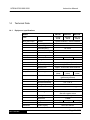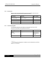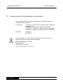
1
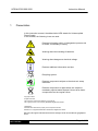
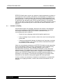
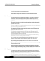
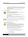
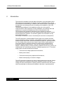
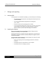
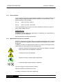
UPS
Uninterruptible Power Supply
MH 700/1000/1500
Instruction Manual
Item number:
032 / 00700MH-000
032 / 01000MH-000
032 / 01500MH-000
October 2009
UPS MH700/1000/1500
Instruction Manual
Contents
MH Series
1
Presentation
4
2
2.1
Warranty conditions
Limitation of liability
5
6
3
3.1
3.2
3.3
3.4
3.5
3.6
3.7
Safety
General safety instructions
Transportation and storage
Setup
Connection
Operation
Handling of batteries
Maintenance, servicing and faults
7
7
7
7
8
8
9
9
4
Introduction
10
5
System description
11
6
6.1
6.2
6.3
6.4
6.5
MH700/1000/1500 – description of equipment
Display and operator control elements on the front panel
Operator control elements on the UPS
Display elements on the UPS
Equipment elements on the rear panel
Audible alarm signals of the UPS
13
13
14
14
16
18
7
7.1
7.2
Storage and unpacking
Storing the UPS
Unpacking the equipment
19
19
19
8
8.1
8.2
8.3
Installing and connecting the UPS
Connecting the UPS
Communications connection on the UPS
Connection sequence
20
21
22
22
9
9.1
9.1.1
9.2
9.2.1
9.2.2
9.2.3
9.2.4
Running and operating the equipment
Operating the UPS equipment
Operating modes and signals
Instructions for using the UPS
Switching on and starting the UPS
Switching off and disconnecting the UPS
Activating the test operation
Communication
23
23
23
25
26
26
26
26
10
Starting up the UPS equipment
27
11
Troubleshooting
27
Page 2 of 36
UPS MH700/1000/1500
MH Series
Instruction Manual
12
Software
29
13
13.1
13.2
13.3
13.4
13.5
Maintenance and servicing
Measuring the bridging time (support time)
Replacing the batteries
Service log
Service hotline
Maintenance and service contracts
30
30
31
32
33
33
14
14.1
14.2
14.3
Technical Data
Equipment specifications
Accessories
List of wearing parts
34
34
35
35
15
Requirements for the declaration of conformity
36
Page 3 of 36
UPS MH700/1000/1500
1
Instruction Manual
Presentation
In this instruction manual, the abbreviation UPS stands for Uninterruptible
Power Supply.
In this manual, the following icons are used:
Denotes information which, if disregarded, poses a risk
to health, functionality or safety.
Warning about the handling of batteries.
Warning about dangerous electrical voltage.
Denotes additional information and tips.
Recycling symbol.
Denotes components subject to the electronic scrap
ordinance.
Denotes components or parts which are subject to
mandatory special waste disposal. Never throw these
components into the regular refuse.
Copyright © 2004
All rights reserved.
This instruction manual is protected by copyright law.
The copyright owner is the company EFFEKTA Regeltechnik GmbH.
Trademarks:
All trademarks used are the property of their respective owners.
EFFEKTA® is a registered trademark of EFFEKTA Regeltechnik GmbH.
We reserve the right to make technical and visual changes, and we are not liable for typographical
errors.
MH Series
Page 4 of 36
UPS MH700/1000/1500
2
Instruction Manual
Warranty conditions
The delivery receipt is considered to be the initial proof of purchase and should
be stored carefully. It is required for all warranty claims. If the product is
transferred to another user, then the latter is entitled to claim under the
warranty for the remainder of the warranty period. The purchase receipt,
together with this declaration, should be transferred to the possession of the
new owner.
We guarantee that this equipment is in a functional state and corresponds in
technical terms to the descriptions in the enclosed documentation.
The warranty period for special equipment corresponds to the minimum period
prescribed by the legislation.
This warranty is not valid for the following cases:
o
Defects due to: damage during transportation, accidents, natural
disasters, misuse, vandalism, inappropriate use, maintenance errors or
incorrect repairs by third parties.
o
Modifications, unauthorized tampering, incorrect operation, another
device or accessory, incorrect installation, or any modification not
approved by us.
o
Disregard for the instructions in the supplied documentation.
o
Incompatibility of the product as a result of technical innovations or
regulations which may come into effect after the purchase.
o
Incompatibility or malfunction caused by product components not
installed by us.
o
Signs associated with the normal ageing process of the product
(wearing parts).
o
Defects caused by external appliances.
The warranty period for parts replaced and/or repaired within the scope of this
warranty expires along with the original warranty of the product.
Equipment sent in without accessories will be replaced without accessories. An
equipment return will only be accepted if it is enclosed in the original
packaging.
Incidental transportation costs are generally excluded from the scope of
services provided under the warranty.
MH Series
Page 5 of 36
UPS MH700/1000/1500
Instruction Manual
EFFEKTA GmbH does not give any express or implied warranties in relation to
this equipment and its quality, performance, merchantability or suitability for a
specific purpose. In some countries, the exclusion of implied warranties is not
permitted by law. In this case, the validity of all express and implied warranties
is restricted to the warranty period. When this period expires, all warranties
cease to be valid. In some countries, a limitation of the validity period of implied
warranties is not permitted by law, in which case the above restriction is not
effective.
2.1
Limitation of liability
Compensation claims are excluded, unless they are based on the deliberate
acts or gross negligence of EFFEKTA GmbH or its employees. The liability
according to the Product Liability Act remains unaffected. Under no
circumstances will we be liable for:
o
Claims for loss or damage made by third parties against you.
o
Loss or damage of your records or data or the cost of recovering these
stored data.
o
Financial consequential damage (including loss of earnings or savings)
or incidental damage, even in the event that we had been informed of
the possibility of such damage.
Under no circumstances whatsoever will EFFEKTA GmbH be held responsible
for any coincidental, indirect, special, consequential or other damage of any
kind (including, without limitation, damage relating to loss of profit,
discontinuation of business, loss of business information or any other loss)
arising from use of the equipment or in any connection with the equipment,
whether based on a contract, compensation, negligence, strict liability, or other
claims, even if EFFEKTA GmbH has been informed in advance about the
possibility of such damage. This exclusion also applies for any liability which
can arise from the claims of third parties against the initial purchaser.
In some countries, the exclusion or limitation of coincidental or consequential
damage is not legally permitted, in which case the above declaration is not
effective.
MH Series
Page 6 of 36
UPS MH700/1000/1500
3
Safety
3.1
General safety instructions
Instruction Manual
Read and pay careful attention to the user manual and the safety instructions
given in this chapter before taking any further action (transportation, storage,
connection, startup, etc.).
Since the UPS equipment works with mains voltage and incorporates
appropriate energy storage (high-capacity batteries) either on the inside or
outside of the device, the instructions in this chapter are very important for all
users and personnel. For this reason, appropriate safety instructions on the topic
of batteries and battery packs are also dealt with here. When using external
battery packs, you must also follow the safety instructions in the manual
provided.
Work on the UPS equipment may only be performed by authorized technical
personnel.
3.2
Transportation and storage
The UPS may only be transported to its destination in the original packaging.
The same applies for relocations or returns.
The equipment may not be transported or stored upside down.
Position the equipment securely during transportation taking the centre of
gravity into account. Due to their weight, UPS equipment with built-in batteries
may fall suddenly if their position shifts slightly.
During storage, secure positioning of the equipment must also be ensured.
3.3
Setup
The UPS is intended for use in ventilated rooms.
During setup or installation, the installation location prescribed by the
manufacturer must be observed.
If the UPS is exposed to extreme and rapid temperature changes, there is a
risk of condensation. Before proceeding, the equipment should be allowed to
acclimatise for at least 2 hours.
Never set up or operate the equipment in a damp environment.
Also keep fluids away from the equipment.
MH Series
Page 7 of 36
UPS MH700/1000/1500
Instruction Manual
The UPS must not be set up near heat sources.
Ensure that the vents of the equipment are not blocked and that the air
circulation is not impeded.
3.4
Connection
Only connect the UPS to a shock-proof socket or, in the case of a terminal
connection, connect the protective earth conductor without fail. Under no
circumstances should the equipment be operated without a protective earth
conductor.
The socket for the house installation must be easily accessible and located in
the vicinity of the UPS. In the case of a fixed connection, ensure the shortest
possible cable lengths.
If power is supplied to the equipment using a generator, the correct poling must
be observed when connecting the UPS.
To connect the UPS to the house installation socket, only a VDE-tested and
CE-labelled mains cable may be used. In the case of a fixed connection, an
appropriate cable must be used.
To connect the consumer load to the UPS, only use VDE-tested and CElabelled electrical cables. In the case of a fixed connection to the consumer
load, an appropriate cable must be used.
The fuse protection for the consumer load must always be installed directly
ahead of it, and never centrally ahead of the UPS.
Do not operate any household appliances and handicrafts tools, e.g. fan
heaters, vacuum cleaners, drills, hairdryers, toasters, etc. via the UPS.
Do not connect any consumer loads to the UPS which could overload the
equipment (e.g. laser printers).
The sum of the earth fault currents of all consumer loads connected to the UPS
must not exceed 3.5 mA.
Keep the connection cables as short as possible and always lay the cables
correctly. Dangers associated with the connection cables such as tripping over
them or damage from crushing, cutting, etc. must be avoided.
3.5
Operation
The mains power cable must never be disconnected during the operation of
the UPS, otherwise the protective earthing of the UPS and also the protective
earthing of the connected consumer loads will be lost.
The UPS equipment includes an energy store (batteries). This means that its
output can be live even if the UPS is not connected to the power input.
MH Series
Page 8 of 36
UPS MH700/1000/1500
Instruction Manual
To completely switch off the UPS, first press and hold the "ON/OFF" button for
more than 3 seconds, wait until the UPS switches off and only then disconnect
the equipment from the mains (remove input fuse or disconnect mains supply
cable from the equipment).
In doing so, ensure that no fluids or foreign bodies enter the UPS.
3.6
Handling of batteries
Warning – danger of electric shocks and burns.
Batteries can cause electric shocks and are capable of producing high shortcircuit currents which can also inflict burns.
Unauthorized persons must be kept away from batteries.
Do not place batteries against heat sources and do not throw them into a fire.
They might explode!
Do not open or destroy batteries. The electrolyte released is extremely
dangerous to people and the environment (danger of burning to skin and eyes,
toxic).
Defective batteries must be disposed of in an environmentally-friendly manner.
Do not throw batteries into the household refuse under any circumstances.
The local disposal regulations must be observed.
3.7
Maintenance, servicing and faults
Warning – danger of electric shocks.
The UPS remains connected to the battery circuit even after it has been
disconnected from the mains power supply, and has a dangerous voltage
potential. Therefore always disconnect the battery circuit before carrying out
servicing or maintenance work and check for zero voltage.
Work on batteries must only be performed and monitored by personnel with
appropriate technical knowledge about the required precautions.
Unauthorized persons must be kept away from batteries.
When working on the UPS, the following precautions must be taken:
o
Remove wristwatches, rings and other metallic objects
o
Only use insulated tools
The UPS must not be dismantled.
MH Series
Page 9 of 36
UPS MH700/1000/1500
4
Instruction Manual
Introduction
This manual is intended to provide basic information on single-phase online
UPS equipment including the functional principle, application of the various
functions and troubleshooting. In addition, this manual contains information on
transportation and storage as well as handling and installation of the UPS
equipment.
The planning guidelines in this handbook relate only to the specific
requirements for UPS equipment. During installation, the national and local
regulations for electrical installations must be followed without fail.
The contents of this equipment description may change as a result of
technological developments. We have endeavoured to make these contents
accurate and clear. However, we would be grateful for information on any
errors which are noted.
We accept no liability for errors in this description and their consequences.
The UPS equipment (Uninterruptible Power Supply) is to protect sensitive
electrical devices such as computers, workstations, electronic points of sale,
mission-critical instruments, telecommunications equipment, process controls,
etc. from faults which may arise as a result of poor power supply quality or
even power failures. Sensitive devices like these require comprehensive
protection against electrical faults. These can be external faults (e.g. bad
weather, operating faults) or faults caused by adjacent devices (e.g. motors, air
conditioning units, processing machines, welding equipment, etc.). The power
supply faults can be summarized as follows:
o
Fast and slow voltage spikes and fluctuations;
o
Mains power failure;
o
Fast and slow frequency spikes and fluctuations;
o
Mains heterodyning or transient voltages
The UPS equipment prepares the mains voltage and ensures that the voltage
values output to the consumer load remain constant. Faults in the mains
voltage are thus prevented from reaching mission-critical devices and cannot
cause any damage to software and hardware, data loss or operating faults.
MH Series
Page 10 of 36
UPS MH700/1000/1500
5
Instruction Manual
System description
The UPS operates continuously according to the double converter principle. It
ensures the preparation of the mains current and delivers an uninterrupted and
fault-free single-phase voltage for mission-critical consumers. In addition to
supplying the consumer loads, the equipment also keeps its internal batteries
in a fully charged state. In the event of a power failure or power fault, the UPS
continues, without interruption, to deliver a clean voltage supply to the UPS
output. During support operation, the energy is drawn from the batteries.
Fig. 1:
Block diagram
MH series
The block circuit diagram shows the individual device modules and illustrates
their interaction in broad terms.
When the mains power failure exceeds the bridging time of the UPS, it shuts
down to prevent deep discharging of the batteries. When the mains power
supply returns, the UPS restarts automatically, supplies the consumer loads
and controls the charging of the battery pack.
Notable performance features of the MH series online UPS include:
MH Series
o
Absolutely no interruption or signal modification during the failure of the
primary mains power supply.
o
Perfect sine voltage at the UPS output. Much improved quality of
output voltage when compared to the mains voltage of the house
network.
o
Processor-controlled bypass operation;
o
Input-side “power factor” correction (>0.95);
Page 11 of 36
UPS MH700/1000/1500
MH Series
Instruction Manual
o
Higher efficiency of inverter > 90% DC / AC;
o
High-performance communications interface (RS232 interface);
Page 12 of 36
UPS MH700/1000/1500
6
Instruction Manual
MH700/1000/1500 – description of equipment
In this chapter, you will be introduced to the various equipment elements and
will be provided with instructions on its operation as well as all details regarding
equipment connections.
6.1
Display and operator control elements on the front panel
Fig. 2:
MH700/ 1000/
1500 – front
view
All of the operator control and display elements required for normal operation
are positioned on the front of the equipment.
MH Series
Page 13 of 36
UPS MH700/1000/1500
6.2
Instruction Manual
Operator control elements on the UPS
Fig. 3:
Display and
operator control
panel for
MH700/1000/1500
UPS "ON/OFF" switch:
(3-way function)
by pressing the button (hold down for approx. 2 seconds) when the UPS is
switched off, it is switched on. (LEDs flash)
If the UPS has already been started and the button is pressed again (onetouch operation), the UPS switches to “test” operation. (Line LED goes out).
by pressing the button (hold down for approx. 2 seconds) when the UPS is
switched on, the UPS is switched off (LEDs go out).
Warning: The equipment will not be completely started or switched off if the
“ON/OFF” button is not pressed for a sufficient amount of time.
Providing the mains power supply remains on via the fuse (positioned at the
rear of the UPS), the charging unit also continues to operate even after the
UPS has been switched off.
6.3
Display elements on the UPS
Generally, all display elements only become active when the UPS is switched
on (started).
Line operation:
the UPS is operating using mains power. If the mains voltage is outside of the
tolerances or if the mains completely fails, this indicator light goes out
immediately. The same applies if the fuse is tripped.
The energy required to continue supplying the UPS output during support
operation is drawn from the battery pack.
Inverter operation:
the UPS inverter is working normally and the UPS output voltage is present.
MH Series
Page 14 of 36
UPS MH700/1000/1500
Instruction Manual
Bypass operation:
the UPS is using the bypass operation. The UPS output is directly connected to
the mains input (see Fig.1). This function is mainly active during the UPS startup
process. Damage to the UPS caused by high starting currents in a consumer
load is thus prevented.
The startup procedure for the UPS is complete when the bypass function
changes over after approx. 20 seconds. Then the bypass indicator light goes
out.
The bypass function is also activated if a serious equipment error develops and
the UPS cannot continue to operate normally. This ensures that the UPS output
continues to be supplied.
Fault operation:
Operating fault in the UPS.
The indicator light goes on if an operating fault exists in the UPS or if a shortcircuit develops at the UPS output.
Warning: the indicator bar described below operates with a dual function!
Battery level:
Capacity status of the battery pack.
As long as the UPS is using the support operation, the capacity status of the
battery pack is displayed here. If the battery pack is fully charged, all indicators
on the indicator bar light up during support operation. As the capacity reduces,
the indicator bar goes out from right to left. When the minimum is reached, only
the red indicator light remains on.
Load level:
Load status of the UPS.
If the UPS is operating with mains power, the indicator bar shows the load
present at the UPS output. If no load exists, the indicator bar goes out
completely. As the load increases, the bar lights up from right to left according to
the increments 20, 50, 100%. If the red indicator light also goes on, then the
UPS is overloaded.
MH Series
Page 15 of 36
UPS MH700/1000/1500
6.4
Instruction Manual
Equipment elements on the rear panel
Fig. 4:
Rear panel view
MH700/
1000/1500
Danger!
All plug connections located on the rear panel (exception: RS232 interface)
have mains power potential when connected.
Even when disconnected, dangerous high voltages can exist at the plug
connections due to charged capacities inside the equipment.
a) Fuse at mains power input:
The mains input is enabled when the fuse is inserted. The fuse is triggered in
the event of high overcurrents or an equipment defect (e.g. internal shortcircuit) and the device is immediately disconnected from the connected mains
power supply.
To simulate a mains power failure, simply remove the fuse or disconnect the
plug connection for the mains power supply.
If all UPS connections have been established and the fuse has been inserted,
the charging unit automatically becomes active, i.e. charging of the internal
battery pack is already underway, without having to start the UPS.
MH Series
Page 16 of 36
UPS MH700/1000/1500
a) Mains power
input
Instruction Manual
IEC 10A receptacle as mains power connector.
The protective earth conductor must be connected without fail!
Please always observe the input voltage indicated on the identification label or
in the technical data of this manual.
c) UPS output
16A shock-proof socket
The protective earth conductor must be connected without fail!
Please always observe the max. possible power output of the equipment,
indicated on the identification label or in the technical data of this manual.
d) Communication
(9-pin D-Sub jack)
All relevant UPS data are transmitted to an appropriate
primary control unit (e.g. PC) via the serial interface. In
addition, a defined shutdown signal can be sent to the
UPS. For this, corresponding software packages are
available (see software chapter).
In addition, the interface with the "mains power failure"
and "low battery" contact signals (LAN) is assigned so
that these signals are available for direct processing.
e) Plug for battery
expansion
This connection is used to link the UPS to an optionally
available external battery pack to increase the bridging
time. The connection may only be made using the cable
supplied when the UPS is switched off. For additional
information, consult the manual for the external battery
pack.
As a safety precaution, always compare the voltages indicated for the UPS and
the battery pack prior to connection. These values must always be the same.
Identification
MH Series
The identification label contains information about:
# Manufacturer
# Equipment model and performance level
# Equipment input values
# Equipment output values
# Item number
# Serial number
# CE and barcode designation
Page 17 of 36
UPS MH700/1000/1500
6.5
Instruction Manual
Audible alarm signals of the UPS
Support operation and high battery capacity:
The following sequence (A) is used for this audible alarm signal
[beep, beep -> long pause (8 s) -> beep, beep -> ..., repeating].
Support operation and low battery capacity:
The following sequence (B) is used for this audible alarm signal
[beep, beep -> short pause (1 s) -> beep, beep -> ..., repeating].
Operating fault or overload:
This audible alarm signal has a continuous tone, sequence (C)
[Beeeeeeeeeeeee....p].
MH Series
Page 18 of 36
UPS MH700/1000/1500
7
Storage and unpacking
7.1
Storing the UPS
Instruction Manual
If the equipment is not installed immediately, you should observe the following:
7.2
o
The equipment and accessories must always be left and stored in the
original packaging.
o
The recommended ambient temperatures for storage are:
+5°C...+30°C.
o
Protect the device and its packaging from humidity.
o
If the anticipated storage period is longer than 4 months, the UPS and
external battery pack (optional) must be operated for a period of
approx. 8 hours to prevent deep discharging of the batteries.
Unpacking the equipment
Remove the shipping carton and packaging material. Always store the
equipment horizontally, never upside down.
Check that the delivery is complete using the shipping note. If the delivery is
incomplete or you have received an incorrect delivery, the supplier must be
informed immediately.
You should also check the delivery for transit damage. Any claims for transit
damage must be made immediately:
MH Series
o
Retain the shipping carton and packaging material for verification
purposes.
o
Immediately inform the manufacturer or your supplier.
o
Immediately inform the shipping company.
Page 19 of 36
UPS MH700/1000/1500
8
Instruction Manual
Installing and connecting the UPS
All requirements in the technical data regarding environmental and operating
conditions must be observed to ensure the trouble-free functioning of the UPS.
The following must be observed when setting up / installing the UPS
equipment:
MH Series
o
Avoid extremes of temperature and atmospheric humidity. A maximum
service life, particularly as far as the batteries are concerned, is
achieved at an ambient temperature of 15 – 25°C.
o
Always ensure that sufficient space is available behind the UPS to
perform the necessary connections. The load-bearing capacity of the
base must be ensured at all times.
o
Observe the specified installation position. The specified installation
position is upright standing only.
o
Ensure ventilation of the equipment. Air is drawn in at the side and
blown out at the rear. Therefore a minimum clearance of at least 50 mm
must be observed on the right, left and at the rear of the UPS. Ensure
an appropriate flow channel.
o
Pay attention to the arrangement of the equipment. When installed in
parent systems (e.g. machine, control cabinet), you must ensure that
the UPS operates within the indicated temperature range. Excess heat
that builds up in the installation space must be removed by means of
external ventilation.
Page 20 of 36
UPS MH700/1000/1500
8.1
Instruction Manual
Connecting the UPS
The MH Series models are equipped with plug connections. The connection
diagram (Fig. 5) and the following information must be observed:
Fig. 5:
Connection of
UPS
MH700/
1000/1500
S:
10 A
1:
0.75
mm²
Warning
The UPS equipment contains components with high voltage and amperage.
Incorrect handling may therefore lead to electrical accidents, sometimes with
fatal consequences or material damage.
The protective earth conductor must be connected without fail! If not, the
consumer loads will also not be earthed.
If power is supplied to the equipment using a generator, the correct poling must
be observed when connecting the UPS.
Warning
The connection diagram shown in Fig. 5 only applies if:
o
the loop resistance is observed up to the last consumer load;
o
earthing of the consumer loads is safely guaranteed;
o
or the consumer loads are separately protected against overcurrents and
leakage currents, and are also earthed.
If the UPS equipment is located in an EMERGENCY-OFF circuit, it must be
noted that if this is activated, the UPS equipment will not de-energized. The
consumer loads will continue to be supplied for the duration of the support time.
MH Series
Page 21 of 36
UPS MH700/1000/1500
8.2
Instruction Manual
Communications connection on the UPS
To facilitate data exchange with the UPS, a convenient communications
interface is available.
For the connection, only use the cables specified in the “Accessories” chapter.
Pin:
Fig. 6: UPS –
internal wiring of
communications
interface
Assignment:
2
LAN
Signal: Mains power
failure
4
LAN
GND
5
LAN
Signal: Battery low
6
RS232
Receive data (Rx) or
shutdown (SD)
7
RS232
GND
9
RS232
Transmit data (Tx)
The communications interface is completely galvanically isolated.
The LAN signals possess a shared earth, which is not linked to the earth of the
RS232.
The UPS can also be forced to shut down immediately via the RS232 serial
interface during support operation. This is triggered via a permanent +12 V
signal on receive data (Rx) (“shutdown” function).
8.3
Connection sequence
Connect the UPS to the mains making sure that the mains and UPS are safely
switched off during the procedure.
Connect the consumer load(s) to the UPS. Ensure that all consumer loads are
switched off.
MH Series
Page 22 of 36
UPS MH700/1000/1500
9
Running and operating the equipment
9.1
Operating the UPS equipment
Instruction Manual
The operation of this equipment is characterized by various operating modes
and signals.
9.1.1 Operating modes and signals
The most important operating modes of the UPS are as follows:
Charging operation:
if the mains power is available and the line-side fuse is switched on, the UPS
charging operation is enabled.
-> The batteries are being charged, but the UPS has not yet been started.
Display/alarm signal: no display or alarm signal is active in this operating mode
as the UPS has not yet been started.
Startup operation:
if the mains power is available, the startup procedure is initiated when the start
button is pressed. The UPS then switches over to bypass operation for approx.
20 seconds. Following this, mains power operation is automatically activated.
If no mains power was available during the startup procedure, the UPS
switches directly to support operation following the startup procedure.
Display/alarm signal: a short progress display characterises the startup
process. No audible alarm signal. By way of example, the bypass operation
phase is shown here. The indicators for inverter, bypass, output load of 100%
(for example) and available mains power light up.
MH Series
Page 23 of 36
UPS MH700/1000/1500
Instruction Manual
Mains power operation:
if the mains power is available and the UPS has completely finished the startup
procedure, the UPS automatically assumes mains power operation.
-> The battery pack is also charged as necessary in this operating mode.
Display/alarm signal: during mains power operation, the inverter and line
indicators as well as the current value of the output load (here 50%) light up. No
audible alarm signal.
Support operation:
if the mains power has failed, the UPS immediately switches to support
operation.
Display/alarm signal: during support operation, the inverter and battery
indicators as well as the available battery capacity (example shown here: 75%)
light up and the line indicator goes out. Sequence (A) is used as the audible
alarm signal.
Overload operation:
if the UPS output is overloaded, the UPS switches to bypass operation.
Display/alarm signal: during overload operation, the inverter and bypass
indicators as well as an output load > 100% light up. Sequence (C) is used as
the audible alarm signal. In addition, the line indicator in this example shows
available mains power.
MH Series
Page 24 of 36
UPS MH700/1000/1500
Instruction Manual
Test operation:
if the UPS is operating using mains power, the test operation can be initiated by
briefly pressing the “ON/OFF” button.
Display/alarm signal: the display, including alarm signal, is the same as in
support operation, although mains power is available.
Fault operation:
if a fault develops in the equipment, the UPS immediately switches to fault
operation.
Display/alarm signal: during fault operation, the fault and bypass indicators light
up. Sequence (C) is used as the audible alarm signal. In addition, the status
‘mains power available’ and an output load of 50% is shown here.
9.2
Instructions for using the UPS
The operator of this UPS equipment must always comply with the instructions
in this manual. The operator may only carry out the following actions and must
also take great care in doing so:
o
Use of the operator control elements: switching on, starting up and
switching off the UPS.
o
Reading the indicator elements and interpretation of the audible alarm
signals.
o
Activation of test operation.
o
Use of communications interface, whereby for UPS equipment with a
fixed connection, the connection to the PC or other systems must
already exist.
Owing to the comprehensive range of protective functions provided by the UPS
equipment for the consumer load(s), the UPS runs completely automatically.
Only switching on and startup or switching off is carried out by the operator. In
addition, data can be exchanged via the communications interface or SNMP
adapter but is not absolutely necessary for general operation of the equipment.
MH Series
Page 25 of 36
UPS MH700/1000/1500
Instruction Manual
9.2.1 Switching on and starting the UPS
To switch on the UPS, connect it to the power supply by plugging in the feeder
cable. Make sure that the mains fuse (located at rear of unit) has been
inserted.
The UPS is started by pressing the “ON/OFF” button. (Keep it pressed down
for approx. 2 seconds.)
The UPS selects the appropriate operating mode upon completion of the
startup procedure.
9.2.2 Switching off and disconnecting the UPS
The UPS can be switched off by pressing the “ON/OFF” button (and holding it
down for approx. 2 seconds) when the UPS is running.
However, the UPS remains in charging mode to keep the batteries fully
charged and ready for operation.
To shut down the UPS equipment completely, the equipment must be
disconnected from the mains by pulling out the feeder cable.
9.2.3 Activating the test operation
Before activating the test operation, you must observe the following points:
o
Inform all employees involved about your intended action.
o
As a safety precaution, back up all the data of your connected consumer
loads.
o
Leave all consumer loads switched on so that the load characteristic
remains unchanged.
o
Ensure that the UPS is in mains power operating mode.
Briefly press the "ON/OFF“ button (touch only).
The UPS then switches to test operation for approximately 10 seconds.
This operating mode is only used to test the function of the UPS.
At this stage, the battery capacity indicator only provides an indication of the
battery pack charge status. This does not necessarily reflect the total capacity
of the battery pack or the overall support time it can provide.
9.2.4 Communication
For the data exchange between the UPS and a parent system, appropriate
software packages are required. The range of products can be found in the
“Software” chapter.
MH Series
Page 26 of 36
UPS MH700/1000/1500
10
Instruction Manual
Starting up the UPS equipment
To guarantee error-free startup, the following actions must be carried out:
1. Establish the connection between the mains and UPS. Check that a
mains fuse has been inserted beforehand.
2. Start the UPS (with the ON/OFF button).
3. Wait until the UPS is in mains power operating mode.
4. Now connect the consumer loads one by one whilst observing the load
indicator.
If all of the steps have been completed successfully, the UPS will be in mains
power operating mode and the load indicator will be less than 100%.
5. Now switch the equipment off (with the ON/OFF button).
6. Wait a few seconds (“refresh”).
7. Restart the UPS (with the ON/OFF button).
The UPS equipment should be in mains power operating mode again after the
stated time of 20 seconds. This test ensures that the system also starts when
the total load is connected.
The equipment can now remain operational in this status.
11
Troubleshooting
Troubleshooting work on the UPS equipment may only be performed by
authorized technical personnel.
If the UPS does not work properly, attempt to resolve the problem with the aid
of the following table:
MH Series
Page 27 of 36
UPS MH700/1000/1500
Instruction Manual
Problem
Possible cause:
Remedy:
The UPS cannot be
started and no alarm
signal is given.
The mains power is not
available to the UPS or
is switched off.
Ensure that all connections
have been established and
confirm this by means of
appropriate voltage
measurements. Check or
replace the fuse for the UPS.
The ON/OFF button was
not pressed down for
sufficient time.
Press the ON/OFF button for
approx. 2-3 seconds.
The UPS is overloaded
on the consumer load
side.
Disconnect the consumer
load or some of the
consumer loads from the
UPS until the load indicator
shows <= 100%.
The bridging time is less The batteries are not
than the rated value.
fully charged, or
individual batteries are
faulty.
Charge the batteries for
more than 8 hours and
repeat the test. If the
problem persists, the
batteries must be replaced.
The UPS is in bypass
operation, the overload
indicator goes on, and
an audible alarm signal
is given (sequence (C)).
The UPS appears to be
working OK, but the
consumer load is not.
The connection between Check the connection and
the UPS and the
confirm it by measuring the
consumer load is faulty. voltage
If the profile of the UPS fault you are experiencing is not in the above table,
inform our service department and make sure you have the following
information to hand:
1. model number, serial number;
2. the date on which the problem occurred;
3. a detailed description of the problem.
MH Series
Page 28 of 36
UPS MH700/1000/1500
12
Instruction Manual
Software
With a suitable software package, settings and operating status of the UPS can
be transmitted and processed via the communications interface. The software
packages can be obtained from the manufacturer / dealer or from the service
hotline provided (“Service” chapter). Here, you can obtain useful information
about suitable software packages relating to your application and UPS. For
more information, you can also consult our Internet home page:
http://www.effekta.com/
The following basic functions are supported by all software packages:
o
Detection and display of the UPS mains power status;
o
Display of the UPS output status;
o
Detection and display of the battery pack charge status;
o
Closing of running applications in the event of a mains power failure;
o
Shutdown of the operating system;
o
Creation of log files;
o
General monitoring of UPS data and statuses (diagnosis function).
For details on individual software packages, such as installation, operation and
the range of features, consult your software manual.
In the "Accessories" chapter, you can find a suitable and tested software
package.
MH Series
Page 29 of 36
UPS MH700/1000/1500
13
Instruction Manual
Maintenance and servicing
A long service life and trouble-free operation from your UPS equipment can be
expected as long as you perform the minimum necessary maintenance.
However, the reliability of the UPS is significantly affected by environmental
conditions. The temperature and atmospheric humidity where the equipment is
located must be kept within the limits. In addition, the area around the UPS
must be kept as clean and free of dust as possible. At the ideal ambient
temperature of 22 °C, the typical service life of the batteries is approx. 4 years.
The service life can be substantially increased (to approx. 8-10 years) by using
special batteries.
At regular intervals (every 6-12 months), you should check that the remaining
bridging time is sufficient for your intended purposes. If this is not the case,
then it is time to replace the batteries.
13.1
Measuring the bridging time (support time)
Before starting this procedure, it is absolutely essential to save all open data.
Also inform all employees who will be affected.
There are basically two methods of measuring the support time. Method a) is
suitable for measuring the actual support time, whereby the consumer loads
will inevitably have zero current at the end of the bridging time.
Method b) enables the residual capacity to be determined after a specific
support time. In this case, consumer loads will not generally be left with zero
current.
To apply one of these methods, force the UPS into support operation by
disconnecting it from the mains or taking out the fuse on the rear of the unit.
After performing the measurement, connect the mains again and start the UPS
as normal by pressing the ON/OFF button.
Bear in mind that the batteries are discharged after the measurement, i.e. the
UPS equipment must operate for several hours (min. 5 hours) in mains power
or charging operation before they become approx. 80% operational again.
If the measurement of the support time is not performed due to local conditions
or directives, we recommend the preventive measure of replacing the batteries
every two years to prevent the risk of inadequate support time due to battery
deterioration.
MH Series
Page 30 of 36
UPS MH700/1000/1500
13.2
Instruction Manual
Replacing the batteries
Before you proceed, take the safety information provided into consideration.
Carry out the work in the specified sequence. Always use safety tool.
Before you start work, make sure that the UPS is switched off and is
disconnected from the mains power supply.
Work on the battery pack may only be carried out by personnel who have
received specific training in the handling of batteries.
It should be observed that high voltages are still present in the appliance even
when it is switched off. This includes the voltage in the battery pack and the
charging voltages in mains capacitors, for example. Appropriate safety
measures are to be taken to prevent electric shock.
Owing to the dangers described above, no further details are provided in this
manual on the replacement of batteries.
A separate description is available on request for the relevant specialist
personnel.
MH Series
Page 31 of 36
UPS MH700/1000/1500
13.3
Instruction Manual
Service log
Always enter all maintenance and servicing work performed on the UPS
equipment into the service log.
Date:
MH Series
Work performed:
Performed by:
Page 32 of 36
UPS MH700/1000/1500
13.4
Instruction Manual
Service hotline
In the event that, contrary to expectations, problems occur with the UPS or you
require safety-related information, please contact our service hotline on the
following phone or fax numbers:
Tel. no.:
0049 / (0) 7542 –9353-0
Fax no.:
0049 / (0) 7542 – 9353-300
If it is not possible for you to get in touch by telephone, we have set up an email contact address for you:
[email protected]
In addition, you can contact the department or subsidiary you need directly at
the following Internet address:
http://www.effekta.com/html/kontakt.html
13.5
Maintenance and service contracts
EFFEKTA Regeltechnik GmbH offers you suitable maintenance and customer
services to ensure the highest possible reliability and availability of your UPS
equipment.
In addition, as part of a maintenance contract, our expert technical personnel
can provide you with support in the following areas:
o
Regular checking of the equipment, especially the batteries, as well as
timely replacement and disposal of batteries;
o
Checking of the UPS installation;
o
Disposal of faulty or deteriorated components;
o
Environmentally-friendly disposal of batteries.
Our entire range of services can be found at:
http://www.effekta.com/html/service.html
or contact us directly at the above addresses.
MH Series
Page 33 of 36
UPS MH700/1000/1500
14
Technical Data
14.1
Equipment specifications
Instruction Manual
Model:
Power:
Mains power input:
UPS output:
Phases
MH700
MH1000
MH1500
700 VA /
490 W
1000 VA /
700 W
1500 VA /
1050 W
1 phase conductor + neutral conductor
Input range
160 -275 V AC
Bypass range
175 -260 V AC
Rated frequency
50 / 60 Hz
Synchronous range
45 – 65 Hz
Power factor
> 95 %
Rated voltage
230 V AC (sine)
Max. output current
3A
4.3 A
Voltage tolerance
Frequency tolerance
+/- 3 % (static)
+/- 0.5 % (support operation)
Overload capacity
[110 ... 130 %]: 10 – 25 s, > 130 % 1.5 s
Bridging time
approx. 10 min under rated conditions
Efficiency:
DC -> AC
DC input
Input voltage
Interface:
LAN / RS232
Environmental data:
Perm. temp. range
> 90 %
24 V DC
(rated)
0 ... +40 °C
+15 ...+ 25 °C
Storage temperature
0 ... +40 °C
Rel. atmos. humidity
20 ... 90 % (non-condensing)
EN 50091-1, EN 50091-2
Technology
Uninterrupted operation, double converter
with auto. bypass switch
Fan cooling
Noise level
Weight
Inspections
MH Series
36 V DC
(rated)
9-pin D-SUB jack
(galvanically isolated)
Cooling
Dimensions
36 V DC
(rated)
Recommended temp.
Standards:
General:
6.5 A
H x B x D [mm]
< 45 dB
12.5 kg
15 kg
15.2 kg
TÜV / GS / CE
190 x 140 x 440 mm
Page 34 of 36
UPS MH700/1000/1500
14.2
Instruction Manual
Accessories
Below is a list of components which have been specifically authorized and
tested for this UPS by EFFEKTA Regeltechnik GmbH:
14.3
Accessory:
Function:
Item number:
“PowerShut Plus”
software package
Network-capable shutdown and
diagnosis software
LAN PowerShut
LAN/RS232 connection
Interface connection cable
M2502
List of wearing parts
The following components are subject to normal wear and tear and are
therefore not included in the warranty for this UPS:
Wearing part:
Function:
Item number:
XXXX XX XX **
Energy store
Equipmentdependent; see
accessories or on
request
Battery
12 V 7 Ah
________
** The wearing parts designation for batteries can be obtained from the fitted
batteries or on request.
MH Series
Page 35 of 36
UPS MH700/1000/1500
15
Instruction Manual
Requirements for the declaration of conformity
The CE-labelled UPS equipment complies with the following harmonized
standards and EC guidelines:
EC guideline:
73/23/EEC (for devices which operate within a restricted
voltage range)
93/&(EEC – supplement to guideline 73/23/EEC
89/336/EEC – guideline on electromagnetic compatibility
92/31/EEC – supplement to EMC guideline 89/336/EEC
Standards:
EN 50091-1
EN 50091-2
An EC declaration of conformity for products with the CE label may be
obtained on request from the following address:
EFFEKTA Regeltechnik GmbH
Rheinwaldstr. 34
78628 Rottweil, Germany
Tel. no.: 0049 / (0) 741 –17451-52
MH Series
Page 36 of 36