1
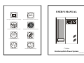
USER'S MANUAL Emergency Backup Power Supply For Use With Computer Loads Only Power Surge/Noise Protection Intelligent Auto-Shutdown Software ℡ Internet Line Protection Cost Efficiency UPS AVR Protection Compact & Reliable Design 1st Edition Uninterruptible Power System IP-020-a8-12 NOTES IMPORTANT SAFETY INSTRUCTIONS Thank you for selecting this uninterruptible power system (UPS). It provides you with better protection for connected equipment. Please read this manual! This manual provides safety, installation and operating instructions than will help you derive the fullest performance and service life that the UPS has to offer. Please save this manual! It includes important instructions for the safe use of this UPS and for obtaining factory service should the proper operation of the UPS come into question. Please save or recycle the packaging materials! The UPS`s shipping materials were designing with great care to provide protection from transportation related damage. There materials are invaluable if you ever have to return the UPS for service. Damage sustained during transit is not covered under the warranty. TROUBLE SHOOTING If the UPS failed to operate properly, please review the following checks firstly. If the problem remain, please consult sales agent for service. Is the Master power switched on? Is the UPS plugged into a correctly working outlet? Is the line voltage within the rating specified? Is the fuse on the rear panel blown? Is the UPS over loaded? Is battery not fully charged? Dead battery? Charger failure? Please provide the following information when call for service. 1. Model number, serial number. 2. Date of the problem occurred, date of purchase. 3. Full description of the problem including load, LCD, and alarm status, installation condition, working environment, etc. CAUTION ¾ The UPS contains voltage that are potentially hazardous. All repairs should be performed by qualified service personal. ¾ The UPS has its own internal energy source (battery). The output receptacles may be alive even when the UPS is not connected to an AC supply. ¾ The UPS is suitable for computers and electronic equipment with substantially rectifier or capacitive loads, not suitable for electronic equipment with significant inductive loads, such as motors & fluorescent lamps. ¾ Be sure to operate within the power rating of the UPS. Below 1/2 or 1/3 of rated power is recommended for longer backup time & longer battery life. ¾ Do not place the UPS near excessive humidity, under sunshine, or close to heat-emitting sources. ¾ If the UPS is out of order, please detach power cord and consult your dealer right away. Do not remove cover if there is no serviceable part inside. ¾ The unit should be supplied by grounded source. Do not operate the unit without ground source. ¾ The socket-outlet should be installed near the equipment and be easily accessible. ¾ Do not plug the UPS power cord into itself. That will result in a safety hazard. ¾ Installation should be performed by a qualified technician or electrician TROUBLE SHOOTING CHART Problem Possible Cause Front panel switch No light, and no alarm (UPS not on) No “Line-on LCD” in off position. Rear panel fuse burnout. Turn on switch. Replace fuse restart UPS. Power cord lose Check input power. Power cord lose Check input power. light, and alarm beeps every few Caution To Take AC Fuse burnout. seconds. Replace fuse, if problem remains, call for service. Recharge the battery for at Backup time is less Battery is not fully least 6 hours, re-test the than the rating. backup time. If problem charger failure. in accordance with local electrical codes. remains, call for service. - 12 - -1- BATTERY FACTS SYSTEM CONCEPT The battery is the only periodically serviceable parts in the UPS. An expected life is approx. 3∼5 years. However, frequent long discharges or ambient temperatures above 80°F will shorten battery life. Therefore, it is recommended to replace the batteries every 3 years after initiating the unit. The purpose to present this chapter is to give you more precise conception about how UPS works.. 1. Block Diagram INPUT Recharge batteries every 3 months is necessary if it is not in use because it may cause batteries over-drain. OUTPUT N.F. N.F. AVR. WARNING Only a qualified technician should replace the battery. Batteries have high short-circuit current capacity; mistakes in connecting or disconnecting can cause connections to arc or weld and could cause severe burns. CHA. Fig. 1 shows how UPS works. STORAGE The UPS should only be stored if the battery is fully charged. Avoid storage temperatures above 80°F as battery life is significantly shortened. Every 90 days remove the unit from storage and plug it in for 24 hours to recharge the batteries. Batteries may be damaged if left in storage and not recharge every 90 days. INV. 2. Normal Operation There are two main loops when AC Utility normal the AC output loop and the battery charging loop. The AC output gets power from AC utility input and pass through AVR to support power to load. In the same time, the AC utility IMPORTANT NOTICE Please use same type and same rating of batteries for replacement. input is converted by AC/DC CHA and support charging power to charge batteries. Do not replace it with the battery that exceeds specified rating. INPUT OUTPUT N.F. N.F. AVR. CHA. INV. Fig. 2 shows how the UPS works when AC Utility normal. - 10 - -3- INSTALLATION AND OPERATION Upon receipt of the UPS, inspect the shipping carton for damage. If there is any obvious damage, immediately report it to the selling dealer or the delivering carrier. If there is no damage to the shipping carton, unpack the unit and inspect the unit for damage. The UPS is designed for installation in a protected environment within a temperature range from 32°F to 104°F and relative humidity of 0∼90% without condensation. Do not block inlets and outlets. Install the system in a location free from excessive dust and chemical fumes. OVERVIEW Front Panel 1. 2. 3. 4. 5. 6. Check the identification label to verify the UPS voltage and power rating match the available line voltage and load requirements. 7. 8. Installation: 9. 1. 2. 3. 4. 5. 6. Check if the main switch on the UPS front panel is in the off position and insure that the voltage of the AC utility source corresponds to the nameplate on the UPS rear panel. Plug the power cable into the grounded socket. If indicators of LINE-ON & CUT-OFF LCD light on, it mean AC power is normal, although UPS is under CUT-OFF status, it still will automatically start to charge by itself. Push the main switch, then the Load Level LCD will light on for 2 seconds and CUT-OFF LCD will light off. The UPS will then get ready and start to work normally. Connect your PC with UPS, then turn on PC. Be sure to check the Load Level LCD indicator and DO NOT OVERLOAD it over 100%. To simulate AC failure (Push UPS test switch) can help to insure whether UPS is in good condition or not. It is designed to alarm every 3 seconds and with BACK-UP LCD light on when simulation starts. If the CUT-OFF LCD is on, it means UPS fault or BATTERY fault. Then you have to contact your local service center When battery approaches low level, alarm will beep every second until auto shut down The 4 conditions UPS will automatically shut down: a. Battery low b. Short circuit c. Overload d. UPS fault -8- UPS Test Switch: When UPS is working under AC mode, it also activates the UPS`s self-test by press the bottom. Master Power Switch: Turn on/off the UPS. LINE-ON: AC Normal . AVR Protection LCD: When AVR is working under protection mode, the light will turn on. BACK-UP: Battery in back-up Over Load: If the UPS is overloaded, the light will turn on and the alarm will sound continuously. UPS Cut-off: Overload or Cut-off Battery Level: A bar graph showing how much of the UPS battery is being used. Load Level: A bar graph showing how much of the UPS power is being used. Rear Panel 1. AC line input socket: Connect power cable from the UPS to AC utility. 2. AC input fuse: Contain the fuse to protect the UPS from over current from incoming AC utility. 3. Output receptacles: Connect power cables of computer equipment to this sockets. 4. Computer interface: This socket combines relay contact signals and RS-232 signals(Option) on DB9 connector. 5. Phone/Fax/Modem jack: Telecom transfer ports provide users to extend the applications. 6. EXT. Battery: Connect external battery cable for battery bank to the UPS. 7. UPS setup switch: Dip1. Low load(below 50w) auto-shut OFF. Low load auto-shut ON. Dip2. DC-start ON. DC-start OFF. Dip3. Buzzer auto-reset OFF. Buzzer auto-reset ON. -5- CONTENTS EXT. BATTERY PAGE Operation process for UPS being fitted with additional Battery Bank for extending back-up time: 1. CAUTION…………………………………………………………..…..1 1. Connect AC Main Power under UPS machine is no load condition. 2. INTRODUCTION 2. To make sure Battery group voltages are same as DC BUS voltages of SYSTEM DESCRIPTION………………………….……………..2 FEATURES………………………………….……………………..2 3. SYSTEM CONCEPT BLOCK DIAGRAM……………………………….………………..3 NORMAL OPERATION………………………….………………..3 AC UTILITY FAILURE………………………….…………………4 4. OVERVIEW UPS machine. 3. Well connect two devices between UPS machine and Battery Bank. 4. Push UPS test button to check UPS machine is working normal to switch to Battery Back-up mode. * Above UPS operation process must be ensured turn on AC Main Power firstly, then connect Battery Bank, In order to avoid spark when connect cable wire between UPS machine and Battery Bank. FRONT PANEL……………………………………………………5 REAL PANEL………………………………………………………5 PICTURE…………………………………………………….…….6 5. INSTALLATION AND OPERATION…………………………………8 6. COMPUTER INTERFACE……..…………………………………….9 7. BATTERY FACTS……………………………………………………10 8. SPECIFICATIONS……………………………………………………11 9. TROUBLE SHOOTING………………………………...……………12 10. EXT. BATTERY…………..……………………….……………….…13 - 13 - INTRODUCTION SPECIFICATIONS Capacity System Description VA 1500VA 2000VA 2500VA 3000VA 110VAC, 115VAC, 120VAC, 220VAC, 230VAC or 240VAC The product is line interactive UPS with the newest technology and powerful Voltage function. The Line Interactive UPS is with AVR function allows input voltage 110VAC, 115VAC, 120VAC, 220VAC, 230VAC or 240VAC Voltage (Batt. Mode) An ideal protection equipment for critical connected loads. Output surge suppression through the modular connectors on the back panel. ±5%, Frequency 50Hz or 60Hz ±1Hz Waveform Modified sine wave Transfer Time The Line Interactive UPS and RUPS2000 monitoring software (Optional kits) makes our computer operate intelligent and provides you with the ability of perfect protection of your critical devices. 50Hz or 60Hz ±5% Frequency range from 75% to 125%, including on line voltage boost-up & buck down. In addition, This UPS provides advanced single telephone line or modem ±25% Input Less than 4ms (typical) 12V/4.5AH HR 1221W 12V/9AH 12V/12AH *4PCS *4PCS *4PCS *4PCS Battery Type Battery Recharge Time Features 5 hours to 90% of full capacity LCD indicator for line on, battery back-up, AVR protection, Indicator LCD Overload and cut-off, Load and battery level ¾ Microprocessor design for true RS-232 (Option). ¾ Line interactive design. ¾ User-friendly LCD display. ¾ Provide boost and buck AVR to stabilize input voltage. ¾ Provides lightning, surge, overload, and short-circuit protection. ¾ Built-in CCCV battery charger and battery over drain protection. ¾ No load auto shutdown (Dip switch setup). ¾ Load level and Battery level display. ¾ Buzzer alarm auto-reset (Dip switch setup). ¾ Auto restart when AC recovery. ¾ Cold start function (Dip switch setup). ¾ Tel / Modem / Fax / Internet surge suppression. ¾ Option Bundle software:Automatically save your valuable files before Alarm Protection Battery Back-up Sounding every 3 seconds Battery Low Sounding every 1 second Overload Continue beeping sound Overload Fuse & current limited Short Circuit Fuse & current limited & cut-off Batt. Low Cut-off Physical No battery drain after cut-off Dimension, D*W*H 408*143*197 mm 32℉-104℉ at full load, 0~90% relative humidity Operating Temperature Environment (non-condensing) Noise Level Contact Closure Less than 40db (at 1 meter) DB9 connector for connecting with Rups-2000 software Interface Smart RS-232 True RS-232 with UPSilon-2000 software (Option) auto shutdown. -2- - 11 - COMPUTER INTERFACE 3. AC Utility Failure If AC utility fails, the UPS quickly detects the problem and activates the inverter. The inverter. The DC/AC inverter changes DC power from the batteries into AC and provides continuous uninterruptible power to load. INPUT OUTPUT N.F. N.F. AVR. CHA. INV. The computer interface (DB9 port) on the back of the UPS may be connected to a host computer. This port allows the computer to monitor the status of the UPS and control the operation of the UPS. The UPSilon-2000 ((option),M2502 Cable), provides complete On-Screen power management to the UPS and computer systems. Its major functions normally include some or all the following: Real-time UPS status on screen. All history records in memory. Auto orderly shutdown for computer & UPS. Multi-server support. Auto file save even without filename preset. Scheduled switch on/off daily or weekly. Pin out information: Fig. 3 shows how the UPS works when AC Utility Failure PIN# PIN1 PIN2 PIN3 PIN4 PIN5 PIN6 PIN7 PIN8 PIN9 Description RS232 DTR, must keep in high state Line fail, normally open, active close N.C. Common for PIN 2,5 Battery low, normally open, active close Two purposes on this pin (1)Remote shut down, keep this pin high (+5~+12V) for 3S will turn off the UPS (2)RS232 Receiver Rx Ground for PIN 6,9 N.C. RS232 Transmitter TX I/O Input Output Output Input Output D-SUB 9 Pin Female Connector Contacts Normally Open 5 2 4 Low Battery Mains Failure Common 7 UPS Shut Down 5 4 3 2 1 9 8 7 6 6 or RS232 RX 1 RS232 DTR Signal High Min. 3 Second 8 9 3 Pin Number -4- -9- RS232 TX Picture: Rear Panel: Front Panel: NEMA5-15R: 3 4 5 6 7 3 AC/BATTERY OUTPUTS CAUTION: RISK OF ELECTRIC SHOCK. DO NOT REMOVE COVER 5 AC/BATTERY OUTPUTS 3 -+ -+ -+ IN 6 -+ -+ -+ OUT INTERNET - EXT. BATTERY 2 4 2 AC F USE 8 9 4 AC F USE 1 7 123 AC INPUT 1 B uzz e r a ut o- re se t O N D c -s ta rt ON REMOTE 123 AC INPUT 1500VA, 2000VA 7 B uzz e r a ut o- re se t O N D c-s ta rt ON REMOTE 2500VA, 3000VA IEC-320: 3 AC/BATTERY OUTPUTS CAUTION: RISK OF ELECTRIC SHOCK. DO NOT REMOVE COVER 5 AC/BATTERY OUTPUTS 3 -+ -+ -+ IN 6 -+ -+ -+ OUT INT ERNET 1 EXT. BATTERY 2 4 2 AC F USE 2 1 7 123 AC INPUT REMOTE 1 B uzz e r a ut o- re se t O N D c -s ta rt ON 7 123 AC INPUT 1500VA, 2000VA REMOTE B uzz e r a ut o- re se t O N D c -s ta rt ON 2500VA, 3000VA -7-6- 4 AC F USE