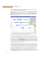
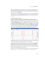
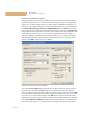
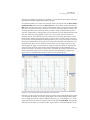
1
.....
TU T O R I A L
Developing a Process Model
Case study :
Reaction /Filtration
DEVELOPING A PROCESS MODEL
The first example of this chapter demonstrates the key initialization and analysis steps for
modeling a process with SuperPro Designer. The fundamental steps and analysis features used
in this example are the same as the steps and features that would be used during the creation of
any other type of process. Therefore, regardless of which type of process you intend to model,
reading through the following example should provide you with the knowledge required to
model processes on your own. In addition, since this example is a batch process, it serves as a
medium for discussing several scheduling issues.
The following files are available for this example in the ‘Examples\Misc’ directory of SuperPro
Designer:
1.
GettingStarted8_0a: This file represents a simple batch process consisting of a reaction
step (Batch Vessel Procedure in a Reactor) and a filtration step (Plate and Frame Filtration
Procedure). The mass and energy balances for this process model are solved in equipment
‘Design Mode’ in order to determine equipment sizing parameters. The development and
solution of this process model are described in sections 2.1b Starting a New Process File up
to 2.1i Simulating the Process and Viewing the Simulation Results. Furthermore, the
specification and analysis of scheduling, equipment utilization and resource tracking
Tutorial 2 -3
2
TU T O R I A L
Developing a Process Model
information for this process model is described in sections 2.1j Setting the Process
Scheduling Information up to 2.1k Viewing Scheduling, Equipment Utilization and
Resource Tracking Results.
2.
GettingStarted8_0b: This file is based on the previous one. The mass and energy
balances are now solved for known equipment sizes in equipment ‘Rating Mode’ in order
to analyze throughput and economic information. A throughput and debottlenecking
analysis for this process is described in section 2.1l Throughput Analysis and
Debottlenecking. Furthermore, the specification and analysis of economic information is
described in section 2.1m Cost Analysis and Economic Evaluation.
For continuous processes, the steps that are related to scheduling of operations within unit
procedures (see 2.1h Initializing Unit Procedures) and of the entire process (see 2.1j Setting
the Process Scheduling Information) do not need to be performed.
2.1a Summary Steps
The steps listed below summarize the process of developing a process model with SuperPro
Designer. These steps are explained in much greater detail in the remainder of this section.
2 -4 Tutorial
1.
Start a new process file by selecting option ‘Start a New Process File’ in the opening dialog
of the program. Alternatively, you may start a new process file later by clicking New ( )
on the Main toolbar or on the File menu of the program.
2.
Initialize the process model using the following items of the Tasks menu: (a) set the plant
operation mode (batch or continuous) using item Set Mode of Operation, (b) register
pure components using item Pure Components ` Register, Edit/View Properties
and stock mixtures using item Stock Mixtures ` Register, Edit/View Properties, and
(c) if the plant operation mode is batch, specify recipe scheduling information using item
Recipe Scheduling Information. You may also want to change the default physical
units of the process model using item Process Options ` Physical Units Options on
the Edit menu.
3.
Build the process flowsheet by adding unit procedures from the Unit Procedures menu
while in Select Mode ( ). Switch to Connect Mode ( ) to draw streams and connect
the unit procedures.
4.
Add operations, such as Charge, Agitation, Batch Heating, Batch Stoichiometric Reaction,
etc., to unit procedures. Different unit procedures have different operations available to
them. Batch/semi-continuous (cyclical) unit procedures can contain one or more
operations, whereas continuous unit procedures are equivalent to unit operations. After the
desired operations have been added, initialize all operations and streams.
5.
Complete the analysis of the process model using the following commands: (a) solve mass
and energy balances and size equipment by clicking Solve M&E Balances ( ) on the
the Main toolbar or on the Tasks menu, (b) classify streams into different categories (e.g.,
raw material, revenue, waste, etc.) using item Stream Classification on the Tasks menu,
and (c) perform costing and economic evaluation calculations by clicking Perform
Economic Calculations ( ) on the Main toolbar or on the Tasks menu. Other analyses
related to scheduling, throughput and debotttlenecking may be optionally performed.
6.
.....
TU T O R I A L
Developing a Process Model
Generate charts and view analysis results using items of the Tasks, Charts and View
menus. Generate and view reports using items of the Reports menu.
2.1b Starting a New Process File
To open SuperPro Designer after it has been installed, select the program shortcut on the
Windows Start Menu or double-click the file ‘Designer.exe’ in the installation directory of the
application. The following dialog box will appear by default:
Figure 2.1: The opening dialog box of the program.
To begin working on a new process file, select the option named ‘Start a New Process File’
from the above dialog and click OK. If you select another option and close this dialog, you can
always start a new process file later by clicking New ( ) on the Main toolbar on the File
menu.
2.1c Specifying the Mode of Operation for the Entire Plant
After you choose to start a new process file, the ‘Process Operating Mode’ dialog box will
appear as shown in Figure 2.2. This dialog box allows you to set the primary mode of operation
(batch or continuous) and the annual operating time available for the entire process. You can
also modify these settings at a later time by clicking Set Mode of Operation on the Tasks
menu.
When the process operating mode is set to ‘Batch’, all stream flows are displayed on a perbatch basis. On the other hand, when the process operating mode is set to ‘Continuous’, all
stream flows are displayed on a per-hour basis. Moreover, no scheduling information is
necessary for plants operating continuously.
Please note that although the plant operation mode can be either batch or continuous, SuperPro
Designer can also model processes that operate in mixed modes. That is, you can have
continuous unit procedures in a batch process plant as well as batch/semi-continuous (cyclical)
unit procedures in a continuous process plant. This is explained later in this chapter (see 2.1h
Initializing Unit Procedures).
Tutorial 2 -5
2
TU T O R I A L
Developing a Process Model
For now, let’s select ‘Batch’ as the operating mode of this example process.
Figure 2.2: The ‘Process Operating Mode’ dialog box.
2.1d Setting the Default Physical Units
SuperPro Designer provides a variety of options for units of measure for the entry and display
of data. To view or modify the default units of the process model, click on an empty area in the
flowsheet and select Process options ` Physical Units Options on the Edit menu.
Alternatively, right-click on the flowsheet to bring up its context menu and select Physical
Units Options.
To activate the Process Options menu item on the Edit menu, you must first click on an empty
area of the flowsheet.
2.1e
Registering Components and Mixtures
COMPONENT DATABANKS
SuperPro Designer provides for the use of multiple component databanks. The following
component databanks can be used:
• the ‘Designer’ databank,
• the ‘User’ databank, and
• the DIPPR databank.
2 -6 Tutorial
.....
TU T O R I A L
Developing a Process Model
Each databank is contained in a separate database file. The ‘Designer’ databank is part of the
‘Designer’ (or ‘System’) database. It provides data for over 530 commonly used compounds.
The ‘User’ databank is part of the ‘User’ database an it is a repository available for users to
store data for their own (or ‘user-defined’) components. The ‘User’ component databank, is
originally (upon installation of the software) empty.
The DIPPR databank draws its data from the relational form of the DIPPR database. This
component database has been developed and maintained at Brigham Young University. A
demo version of the DIPPR databank with only 5 components is shipped with SuperPro
Designer.
To change the location of the database files where each of the above databanks is stored, click
Availability, Passwords and Locations on the Databanks menu to display the ‘Databases:
Availability, Passwords and Locations’ dialog. For example, if the full DIPPR databank is
available or if you want to use a different user database file that somebody else created, you
must specify its location through that dialog; for more details, see 15.1 Database Registration.
REGISTERING COMPONENTS
All the components that will be used in a process model must be registered first. To register
components (in other words, to make them available in your process model), select Pure
Components ` Register, Edit/View Properties on the Tasks menu. This will activate the
dialog shown below.
Figure 2.3: The pure component registration dialog box.
Note that pure components ‘Nitrogen’, ‘Oxygen’, and ‘Water’ are registered by default in
every new process model and cannot be deleted. For this example process, you will need to add
Tutorial 2 -7
2
TU T O R I A L
Developing a Process Model
‘Heptane’ to the list of registered pure components (shown on the RHS of this dialog) as well.
To add ‘Heptane’, you can either scroll down to it in the list of available pure components in
the ‘Designer’ database (shown on the LHS of this dialog), or you can begin typing “heptane”
in the box above the list (see Figure 2.3) and the database will automatically scroll to the
correct location. Next, click Register (
) to add ‘Heptane’ to the list of registered pure
components for this process model. Alternatively, you may double click on ‘Heptane’ in the
database listing and it will be added to your list of registered components.
If a component is not available in the existing component libraries, you can click New ( ) on
the ‘Registered Pure Components’ toolbar to create a new component for your process model.
This will be automatically added to the list of registered components. For this process, you will
need to create components ‘A’, ‘B’, and ‘C’. These components will represent the reactants and
products of a simple reaction. To create component ‘A’, click New ( ) and in the ‘New
Component Definition’ dialog that appears (see Figure 2.4) fill-in the letter “A” for the ‘Name’
field. Notice that as you type, the contents of the ‘Name’ field are automatically copied to all
other fields (‘CAS Number’, ‘Trade Name’, ‘Local Name’, ‘Formula’, and ‘Company ID’).
As far as the program is concerned, you do not need to have correct CAS Numbers, Formulas,
etc. You just need to have something written in each of these six fields. The ‘Local Name’ is
the one that appears in the reports and all the input/output dialog windows of the program.
Notice that at the bottom of this dialog, you can choose to initialize the properties of the new
component by copying them from some other database component or registered component.
For this example, click OK to copy the properties of component ‘Water’ which is available in
the ‘Designer’ database to component ‘A’.
Figure 2.4: The ‘New Component Definition’ dialog box.
After you have added component ‘A’ to your list of registered components, follow the same
steps to add components ‘B’ and ‘C’. When you have completed this, you should edit some of
2 -8 Tutorial
.....
TU T O R I A L
Developing a Process Model
the properties of these components. To access the properties of component ‘A’, double-click on
the component in the list of registered pure components. Alternatively, you can highlight the
component (by clicking on it) and then click Properties (
) on the ‘Registered Pure
Components’ toolbar. This will bring up the ‘Pure Component Properties’ dialog box for
component ‘A’. Through this dialog you can view or edit a component’s physical and
environmental properties, cost data, and regulatory information.
For the purposes of this example, the only physical parameter we will be concerned with is the
molecular weight (MW). Please go to the ‘Physical (Constant)’ tab and change the MW of
component ‘A’ to 150 g/gmol as shown in Figure 2.5. Also, visit the ‘Economics’ tab and
specify a purchasing price of $10/kg. Then, click OK to close the dialog.
Figure 2.5: Editing the constant physical properties of component ‘A’ in the example.
Next, please visit the properties dialog for component ‘B’ and enter a MW of 25 g/gmol and a
purchasing price of $15/kg. Also, visit the properties dialog for component ‘C’ and enter a MW
of 175 g/gmol and a selling price of $300/kg. This completes your initialization of components
for our simple example.
To delete a registered pure component, highlight that component in the list of registered pure
components and click Delete (
) on the ‘Registered Pure Components’ toolbar.
You can add registered pure components, which you have created or modified, to the ‘User’
databank, so that you can register these components in other files as well. To add a component
to the ‘User’ databank, first select the databank in the ‘Source DB’ drop-down list. Then,
highlight a registered component and click on the Deposit button:
Tutorial 2 -9
2
TU T O R I A L
Developing a Process Model
The current version of SuperPro Designer does not make use of the Normal Freezing Point of
pure components. The corresponding field entry, which can be found in the ‘Physical
(Constant)’ tab of the ‘Pure Component Properties’ dialog, can be ignored.
REGISTERING MIXTURES
Mixtures are used to facilitate initialization of input streams in cases where certain raw
materials (e.g., buffers) are consumed as mixtures. In order to register a mixture, click Stock
Mixtures } Register, Edit/View Properties on the Tasks menu and follow the same steps as for
registering pure components.
2.1f Saving and Opening Files
At this point, please save your file by clicking Save As from the File menu and giving your
process model a descriptive name in the Windows ‘Save As’ dialog box that appears. In
general, it is a good idea to save your work often in order to avoid having to redo work in the
event of a program crash.
When working with larger process files, include the date or some other version indicator in the
saved case name.
If the program does crash, there is sometimes a possibility that you will not be able to re-open
the file you were most recently working on. In that case, you should try to open the backup
versions of your file. Anytime you save a newer version of your file, SuperPro Designer will
also save a backup copy of the previous version using file extension ‘.sp~’ (as opposed to a
normal ‘.spf’ file). If the ‘.sp~’ backup file already exists, SuperPro Designer will first create a
copy of that file using file extension ‘.s~~’ as a second backup.
To open a file, click Open from the File menu. This will bring up the Windows ‘Open’ dialog
box. To open a backup file, simply go to the directory where you saved your original file, select
the corresponding ‘.sp~’ or ‘.s~~’ backup file (select ‘All Files (*.*)’ in the ‘File Type’ field of
the dialog box) and click the Open button.
Note that the corresponding file extensions for the original, backup, and second backup files in
EnviroPro Designer are ‘.epf’, ‘.ep~’ and ‘.e~~’.
2.1g
Building the Process Flowsheet
ADDING UNIT PROCEDURES
The first step in building a flowsheet is to add processing steps (unit procedures) to the process.
A unit procedure is defined as a series of operations that take place within a piece of equipment.
The types of operations available depend on the type of unit procedure you are using. As
explained later in this chapter (see 2.1h Initializing Unit Procedures), batch/semi-continuous
(cyclical) unit procedures can contain one or more operations, whereas continuous unit
procedures are equivalent to unit operations.
To add a unit procedure to the flowsheet, first select the desired unit procedure from the Unit
Procedures menu. For our example, please select Batch Vessel Procedure ` in a
Reactor. Notice that after you select a unit procedure and move the mouse pointer to the
flowsheet area, it changes to the ‘add step’ pointer (
). This indicates that your next mouse
2 -10 Tutorial
.....
TU T O R I A L
Developing a Process Model
click on the flowsheet will lay down the icon of the selected unit procedure in that location.
Please click near the left side of the flowsheet to lay down the icon of the selected unit
procedure. SuperPro Designer automatically adds a default procedure name (‘P-1’), host
equipment name (‘V-101’) and procedure description (‘Vessel Procedure’) below the icon.
After you have added a Batch Vessel Procedure in a Reactor to the flowsheet, please add a
Plate and Frame Filtration Procedure by clicking Filtration ` Plate and Frame Filtration
on the Unit Procedures menu and then clicking somewhere to the right of the vessel
procedure icon. Your flowsheet should now look something like this:
Figure 2.6: The example process with the Batch Vessel Procedure in a Reactor and Plate and Frame
Filtration Procedure icons added.
If you decide to abort the addition of the new unit procedure, you can simply hit the Esc key
on your keyboard.
If you wish to modify the default equipment prefixes (e.g. ‘V’ for a Stirred Reactor (CSTR)
vessel and ‘PFF’ for a Plate & Frame Filter), click Application Settings on the File menu
and go to the ‘Prefixes’ tab. To edit the prefix of an equipment resource, highlight that
equipment in the available list and click on the corresponding prefix. Through the same tab,
you can also modify the default operation prefixes in the same manner; for more details, see
8.20 Application Settings.
Tutorial 2 -11
2
TU T O R I A L
Developing a Process Model
Moving, Copying and Deleting Unit Procedures
The following guidelines show how you can move or delete unit procedures in a flowsheet, and
how you can cut or copy and paste unit procedures to a different location in the same flowsheet
or in another flowsheet.
First, you need to select the desired unit procedure icon(s). You can select a single icon by
clicking on it. You can select multiple icons by either dragging an enclosing rectangle around
them, or by adding icons to the selection. To add an icon to the selection, click on it while
holding down the Ctrl key. To remove an icon from the selection, Ctrl+Click on it again. To
select an entire flowsheet, click Select All on the File menu or press Ctrl+A.
Ź To Move Unit Procedures...
1.
Select the desired unit procedure icon(s).
2.
Drag the selected icon(s) to the new location. If multiple icons are selected, you can drag
any member of the selection and all icons will move simultaneously. You can use the arrow
keys to move the selection one pixel at a time.
Note that when you move a unit procedure icon that has streams attached to it, all streams will
move with it. If two unit procedures are connected through an intermediate stream and both the
source and destination unit procedures move, then the stream will keep its structure intact and
move with them. If one of the stream’s ends remains anchored while the other end is being
moved, then the stream will adjust its first and/or last elbow to accommodate the change of
location; for more details on streams, see ‘Adding Streams’ on page 2 -14.
Ź To Delete Unit Procedures...
1.
Select the desired unit procedure icon(s).
2.
Hit the Delete key on your keyboard or click Clear on the Edit menu. The selected unit
procedure(s) will be erased.
When you delete a unit procedure, all streams attached to it will also be deleted.
Ź To Cut or Copy and Paste Unit Procedur es...
SuperPro Designer allows you to cut or copy unit procedures into the clipboard so that you can
subsequently paste them to a different location, either in the same flowsheet or in another
flowsheet. To do this:
1.
Select the desired unit procedure icon(s).
2.
To cut the icon(s), click Cut on the Edit menu (or press Ctrl+X). To copy the icons, click
Copy on the Edit menu (or press Ctrl+C).
3.
Move the mouse cursor to the desired area in the same flowsheet or in another flowsheet
and click Paste on the Edit menu (or press Ctrl+V) to paste the icon(s).
The following restrictions apply to the use of the Cut, Copy and Paste features:
2 -12 Tutorial
.....
TU T O R I A L
Developing a Process Model
1.
You cannot cut or copy and paste streams alone. Streams are placed onto the clipboard only
if you cut or copy multiple unit procedures.
2.
When pasting unit procedures into a flowsheet, you should be aware that certain features of
the original unit procedures are not transferred into the newly created copy:
(a)
When you cut or copy a single unit procedure, attached streams are not included in the
pasted set.
(b)
If the start time of the first operation of the pasted unit procedure was defined on a relative
basis (e.g., with respect to the start or end of another operation in some other procedure),
then the scheduling of the pasted procedure is reset to remove the coupling.
(c)
If the original unit procedure was sharing equipment with another procedure, the pasted
procedure is reset to be executed in its own equipment.
3.
Pasting streams and certain processing steps with component- and stock mixture- related
specifications from one flowsheet to another is not possible unless all components and
stock mixtures of the source process model exist in the destination process model as well. If
that is not the case, the program will automatically expand the set of registered pure
components and stock mixtures in the destination process to include the missing ones.
If you want to paste icons into another application (e.g., a word processing application),
please consult Chapter 14 (Exchanging Data with Other Apps).
Accessing the Help Files
In many equipment resources that host unit procedures, there are dedicated ports, such as
‘Feed’, ‘Vent (Emissions)’, ‘Cake Removal’, ‘Filtrate Removal’, etc. To see which ports are
Figure 2.7: The help topic for the Plate and Frame Filtration Procedure.
Tutorial 2 -13
2
TU T O R I A L
Developing a Process Model
dedicated to each function, you can look up the desired equipment or unit procedure in the
program’s Help system, which is available through the Help menu. This provides access to
supporting documentation shipped with the software, such as the electronic version of the
User’s Manual and additional content.
As a shortcut to the Help menu for any unit procedure, you can click Help ( ) on the Main
toolbar and then click on the unit procedure icon you are interested in. Alternatively, you can
click on the unit procedure icon and hit the F1 key. Note that you can also use the Help ( )
button feature as a shortcut to access the Help files for other interface elements, such as menu
options, toolbar buttons, dialog boxes and dialog tabs.
At this point, please open the Help file for the Plate and Frame Filtration Procedure. A portion
of that file is shown in Figure 2.7. Notice that dedicated ports of the host equipment (Plate &
Frame Filter) are labeled next to its icon. The Help file for each unit procedure also contains a
general description, links to its operation models and to the host equipment, and much more.
ADDING STREAMS
After you add a unit procedure to the process flowsheet, you can add streams. There are three
types of streams:
• feed (input) streams,
• intermediate streams, and
• product (output) streams.
Feed streams do not have a source unit procedure and in batch processing they are mainly
utilized by charge operations. Intermediate streams connect two unit procedures and they are
used to transfer material from the source to the destination unit procedure. Product streams do
not have a destination unit procedure. All streams are automatically identified with a stream
tag.
In order to add streams to the flowsheet, you must first click Connect Mode ( ) on the
Main toolbar. When you do this and return to the flowsheet, the mouse pointer changes to the
‘add stream’ pointer (
) to indicate that you are in ‘Connect Mode’ (as opposed to ‘Select
Mode’). Then, you can add feed, intermediate, and product streams as described below:
Ź To Add a Feed Stream...
1.
Click on an empty area in the flowsheet to initiate drawing of the stream. Notice that as you
move the mouse pointer over the inlet and outlet ports, it changes to a ‘port’ pointer (
).
2.
Move the mouse pointer over the desired inlet port of the destination unit procedure and
once the ‘port’ pointer is displayed click on the port to terminate the stream line. SuperPro
Designer automatically draws the feed stream symbol at the beginning of the stream and
labels the stream.
Ź To Add an Intermediate Stream...
1.
2 -14 Tutorial
Move the mouse pointer over the desired outlet port of the source unit procedure and once
the ‘port’ pointer is displayed click on the port to initiate drawing of the stream.
2.
.....
TU T O R I A L
Developing a Process Model
Move the mouse pointer over the desired inlet port of the destination unit procedure and
once the ‘port’ pointer is displayed click on the port to terminate the stream line. SuperPro
Designer automatically labels the stream.
Ź To Add a Product Stream...
1.
Move the mouse pointer over the desired outlet port of the source unit procedure and once
the ‘port’ pointer is displayed click on the port to initiate drawing of the stream.
2.
Double-click on an empty area of the flowsheet to terminate the stream. SuperPro Designer
automatically draws the product stream and labels the stream.
Note that between initiation and termination of a stream, you may optionally click at
intermediate points on the screen to create right angle bends. This permits customizing of the
stream route and flexibility in flowsheet design. You can cancel the stream-drawing process at
any time by simply hitting the Esc key on your keyboard. Then you can restart the streamdrawing process by clicking Connect Mode ( ) again on the Main toolbar. To delete a
stream, simply hit the Delete key on your keyboard.
At this point, please add the feed, intermediate, and product streams to your example process.
Your flowsheet should now look like what is shown in Figure 2.8:
Figure 2.8: The example process flowsheet with streams added.
Tutorial 2 -15
2
TU T O R I A L
Developing a Process Model
Changing the Appearance of Streams
When SuperPro Designer is in ‘Select Mode’ and the mouse pointer is over a stream line, it
changes to a ‘menu’ pointer (
) to indicate the availability of a stream context menu (see
Figure 2.9). This menu can also be displayed by right-clicking on a stream line.
Figure 2.9: The stream context menu.
Through the stream context menu, you can view or edit (in case of input streams) the
composition, flowrate, and other stream properties using item Simulation Data, select
different stream initialization options using item Initialization Options, change the tag name
(label) of the stream using item Edit Tag Name, adjust the elbows of the stream line using
item Edit Elbows, edit the stream style (e.g., label and line color, line thickness, etc.) using
item Edit Style, etc. Note that double-clicking on a stream line is equivalent to clicking
Simulation Data on the stream’s context menu.
At this point, please right-click on input stream ‘S-101’ of the vessel procedure ‘P-1’ and click
Edit Tag Name on the stream’s context menu. Change the name of the stream to ‘Heptane’
and click OK. Then, right-click on the ‘Heptane’ stream line and click Style ` Edit Style to
display the ‘Stream Style’ dialog. In the ‘Stream Line’ tab (see Figure 2.10) of this dialog, click
Pen Color (
) on the ‘Stream Line’ toolbar and change the color to blue. Also click Pen
Size (
) on the same toolbar and change the size to 2 pixels.
Figure 2.10: The ‘Stream Line’ tab of the ‘Stream Style’ dialog box.
2 -16 Tutorial
.....
TU T O R I A L
Developing a Process Model
Now, switch to the ‘Name Label’ tab. Click Font Color (
) on the ‘Color / Font’ toolbar
and change the color to teal. Also, click Font ( ) on the same toolbar and change the font
style to bold and the font size to 12. Then, click the ‘Name Label: Location’ tab, change the
segment preference to ‘Vertical Near Source’ and click OK.
Next, please change the name of stream ‘S-106’ (the stream that is connected to the dedicated
cake removal port of the Plate & Frame Filter) to ‘Cake’. Also, apply the style of the ‘Heptane’
stream to the ‘Cake’ stream and to the intermediate stream ‘S-105’ using the shortcut method
described below:
Ź To Apply the Style of a Stream to Several Other Streams...
1.
Right-click on the source stream line (e.g., the ‘Heptane’ stream in the example) and click
Style ` Pickup Style.
2.
Right-click on the desired target stream line(s) (e.g. the ‘Cake’ and ‘S-105’ streams in the
example) and click Style ` Apply Style.
After applying these changes, your streams should look something like this:
Figure 2.11: The example process flowsheet after the names and styles of streams have been changed.
For more information on stream drawing, see 4.10 Classification of Input and Output Streams.
Tutorial 2 -17
2
2.1h
TU T O R I A L
Developing a Process Model
Initializing Unit Procedures
SPECIFYING THE OPERATING MODE OF UNIT PROCEDURES
Each unit procedure added to the process has its own operating mode setting. This can be
either:
• batch/semi-continuous, or
• continuous.
Batch/semi-continuous (cyclical) unit procedures can contain one or more operations, whereas
continuous unit procedures are equivalent to unit operations. There are unit procedures that are
inherently batch/semi-continuous (e.g., the Batch Vessel Procedure in a Reactor employed in
this example) and can only be operated in batch/semi-continuous mode. You can have
batch/semi-continuous unit procedures in continuous process plants. Other unit procedures are
inherently continuous (e.g., the Centrifugal Pumping unit procedure which is available by
clicking Transport (near) ` Liquids ` Centrifugal Pump on the Unit Procedures
menu). By default, these can be operated in either mode. Thereby, you can have continuous unit
procedures in batch process plants. Note that the operating mode of inherently continuous unit
procedures is initially set to batch/semi-continuous in batch process plants and continuous in
continuous process plants.
You can access or modify (where both options are available) the operating mode of a unit
procedure through its context menu. Please right-click on a unit procedure icon bring up its
context menu. The context menu of vessel procedure ‘P-1’ after operations are added in this
example is shown in Figure 2.12. To view the operating mode setting of a unit procedure, click
Procedure Data. This will display the ‘Procedure Data’ dialog for that unit procedure. The
operating mode specifications can be found in the ‘Scheduling’ tab of that dialog; for more
details on the operating mode of unit procedures, see Chapter 5 (Procedures & Operations).
Figure 2.12: The context menu of the Batch Vessel Procedure in a Reactor in the example.
The meaning of each item in the context menu of a unit procedure is explained below:
• The Operation Data item allows you to access or modify the simulation parameters of
the operations that have been added to the unit procedure. Note that this item is not
2 -18 Tutorial
.....
TU T O R I A L
Developing a Process Model
available if no operations have been added to the unit procedure. If the unit procedure
contains a single operation, clicking on this menu item will bring up the ‘Operation Data’
dialog for that operation. If it contains more than one operations, clicking on this menu
item or simply moving the mouse pointer over it will bring up a drop-down list of all added
operations. Clicking on an operation in that list will bring up its ‘Operation Data’ dialog.
• The Add/Remove Operations item allows you to add/remove operations to/from the
unit procedure and change the sequence in which these operations are executed. This item
is only available for unit procedures that are operated in batch/semi-continuous mode.
• The Procedure Data item allows you to access or modify the simulation parameters of
the unit procedure, such as the operating mode (continuous or batch/semi-continuous) and
additional scheduling, throughput analysis and debottlenecking information.
• The Procedure State Properties item allows you to access or modify thermodynamic
state properties of pure components during each operation.
• Through the Procedure Activity Overview item, you can view a summary of scheduled
operations, processed material, and equipment contents during the execution of the unit
procedure.
• The Equipment Data item allows you to access or modify the simulation parameters of
the host equipment, such as sizing, costing, and scheduling information.
• The Equipment Contents item allows you to access or modify the initial equipment
contents, and also view a summary of the thermodynamic properties and composition of
the equipment contents during the execution of the unit procedure.
• The Set Break Points item allows you to place stops in the sequential solution of mass
and energy balances. This is normally used for troubleshooting in large or complex process
simulations.
• The Edit Labels item allows you to change the name of the unit procedure, the name of
the host equipment and the description of the unit procedure. For example, you can change
the default unit procedure name (‘P-1’), equipment name (‘V-101’) and unit procedure
description (‘Vessel Procedure’) for the vessel procedure in this example.
• The Disconnect item deletes all streams connected to the unit procedure.
• The Flip (reverse flow direction) item allows you to change the flow direction of the
unit procedure icon from left-to-right (default) to right-to-left and vice versa. You can also
do that by clicking Flip Horizontally (
) on the Visual Objects Toolbar (see 13.5
Visual Objects Toolbar). Note that this option is only available when the unit procedure
does not have any streams attached to it.
• The Order item forces the unit procedure icon to appear behind or in front of other icons,
text, etc.
Tutorial 2 -19
2
TU T O R I A L
Developing a Process Model
• The Style item allows the user to edit such things as the icon color, the tag name color and
font, etc.
• The Help (F1) item provides access to the Help file of the unit procedure.
ADDING OPERATIONS TO UNIT PROCEDURES
The next step toward initialization of unit procedures is to add relevant operations to each unit
procedure. This step is generally required for unit procedures that are operated in batch/semicontinuous mode. For convenience, some inherently batch/semi-continuous unit procedures
may initially contain one or more operations when added to the process (e.g., the Plate and
Frame Filtration Procedure used in this example initially has a Cloth Filtration operation). An
equivalent operation is always added to unit procedures that are inherently continuous, when
these are added to the process (e.g., the Centrifugal Pumping unit procedure will contain a
Centrifugal Pumping operation).
In order to add operations to a unit procedure that is operated in batch/semi-continuous mode,
you can either:
• double-click on a unit procedure icon, or
• right-click on the unit procedure icon and select Add ` Remove Operations from the
context menu of that unit procedure. Note that this menu item is only available for unit
procedures that are operated in batch/semi-continuous mode.
Either action will bring up the ‘Operation Sequence’ dialog (see Figure 2.13) for the selected
unit procedure.
Double-clicking on a continuous unit procedure (e.g., a Centrifugal Pumping unit procedure
added to a continuous process plant) brings up the dialog window of its operation instead of
the ‘Operation Sequence’ dialog. Essentially, a unit procedure that is operated in continuous
mode behaves like a single operation.
At this point, please open the ‘Operation Sequence’ dialog for the vessel procedure (‘P-1’) in
the example. Add a Charge operation to the operation sequence for this unit procedure by
double-clicking this item in the list of available operations. Alternatively, you can highlight this
item and click Add (
) to add the new operation at the end of the operation sequence or
Insert (
) to insert the new operation before the highlighted operation in the operation
sequence. To delete an operation from the operation sequence, click Delete (
) on the
available toolbar. If you add an operation in the wrong order, you can change its position in the
operation sequence using the Move Up (
), Move Down (
), Move to Top (
), and
Move to Bottom (
) buttons on the same toolbar.
Notice that when the charge operation is initially named ‘CHARGE-1’ when it is added to the
operation sequence. Double-click that item (or highlight that item and click Rename ( ) on
the available toolbar) and change the name of the added charge operation to ‘Charge Solvent’.
Now, add two more Charge operations, a ‘React (Stoichiometric)’ (Batch Stoichiometric
Reaction) operation, and a Transfer Out operation, to the operation sequence. Rename these
operations to ‘Charge React A’, ‘Charge React B’, ‘React’ and ‘Transfer to PFF-101’,
2 -20 Tutorial
.....
TU T O R I A L
Developing a Process Model
respectively, so that your dialog box looks like the one shown in Figure 2.13. Then click OK to
return to the process flowsheet.
Figure 2.13: Adding operations to the Batch Vessel Procedure in a Reactor in the example.
Subsequently, please open the ‘Operation Sequence’ dialog for the filtration procedure (‘P-2’)
in the example. Notice that this unit procedure has a ‘Filter’ (Cloth Filtration) operation (named
‘FILTER-1’) added to its operation sequence by default. Use the same method as before to add
a ‘Wash Cake’ (Cake Wash) operation (named ‘CAKE-WASH-1’) and a Transfer Out
operation (named ‘TRANSFER-OUT-1’) to the operation sequence. You can keep the default
names for these operations.
INITIALIZING THE OPERATIONS
The next step is to initialize the operations added to the two unit procedures as described below.
Batch Vessel Procedure in a Reactor
Please right-click on the vessel procedure (‘P-1’) to bring up its context menu and click
Operation Data ` Charge Solvent (Charge). This will bring up the ‘Operation Data’
dialog for the ‘Charge Solvent’ operation. Through this dialog, you can access or modify the
simulation data for an operation, such as the operating conditions, scheduling data, emission
specifications, and labor-related information. This data is grouped into several tabs. Note that
Tutorial 2 -21
2
TU T O R I A L
Developing a Process Model
different tabs may be available for different operations. The operating conditions (‘Oper.
Cond’s’) tab for the ‘Charge Solvent’ operation of this example is shown in Figure 2.14.
Figure 2.14: The ‘Oper. Cond’s’ tab for the first Charge operation (‘Charge Solvent’) in procedure ‘P-1’.
To initialize the operating conditions for the ‘Charge Solvent’ operation, you begin by selecting
the charge stream for this operation. Use the ‘Charge Using’ drop-down list at the top of the tab
to select the stream which you renamed ‘Heptane’ earlier in this section. Then, click on the
View/Edit Stream Composition and/or Amount ( ) button next to the drop-down list
in order to access the simulation data dialog for that stream (see Figure 2.15) and specify its
2 -22 Tutorial
.....
TU T O R I A L
Developing a Process Model
composition. To add ‘Heptane’ to the stream, double-click on the corresponding item in the
‘Registered Ingredients’ listing for that stream.
Figure 2.15: The simulation data dialog for the ‘Heptane’ stream.
Please note the following with respect to the simulation data dialog of streams:
1.
You can charge multiple components in the same stream if you wish. To do this, simply
add additional component names from the ‘Registered Ingredients’ listing. If the
‘Ingredient Flows’ option is selected, you can specify the corresponding amounts of added
ingredients. The computer will automatically calculate the mass (%) and concentration (g/L
or mole/L) of each ingredient, the stream’s density (if it is not set by the user), the
volumetric flowrate and the activity of the stream. If the ‘Mass Composition’ option is
selected, you can specify the total mass or volume flow and the mass (%) of each
component. You may also select units for entry and display.
2.
In addition to pure components, stock mixtures can be fed (or “charged”) into a process
step using an input stream. To add a stock mixture to the stream, select the ‘Stock
Mixtures’ option for registered ingredients and follow the same guidelines as for adding
components.
3.
As an alternative to going through the simulation data dialogs of operations to edit stream
properties, you can initialize and edit input streams directly from the flowsheet itself. To do
this, double-click on a stream (or right-click on a stream and click Simulation Data from
the context menu of that stream). This will bring up the same dialog box as the one shown
in Figure 2.15. Note that only the feed (input) streams to the flowsheet need to be specified.
Tutorial 2 -23
2
TU T O R I A L
Developing a Process Model
The flowrates and compositions of intermediate and output streams are calculated by the
program. However, the user can specify the physical state properties of these streams.
4.
For biotech processes, the extracellular percentage (‘Extra-Cell %’) of an ingredient
represents the fraction of that ingredient in the bulk solution (as opposed to inside the cell).
For more information on this topic, please refer to the ȕ-Galactosidase example (see 2.3
The b-Galactosidase Process).
5.
If the plant operation mode is batch, all flowrates are reported on a per-batch basis (or per
cycle of source or destination process step). If the process plant is set to operate in
continuous mode, then all flowrates are reported on a per-hour basis. The choice for mass
units can be made from each stream’s dialog. This choice overwrites the default choices of
physical units for the whole process as specified by selecting Process Options `
Physical Units Options on the Edit menu.
6.
The ‘Environmental Properties’ tab of a stream’s simulation data dialog displays the
concentrations and daily throughputs of the environmental and aqueous properties of the
stream (TOC, CaCO3, TP, TKN, COD, ThOD, BOD5, BODu, etc). All values are for
display only and cannot be edited by the user through this dialog box. However, the
environmental properties of the pure components contained in that stream (which
contribute to the above stream properties) can be edited by selecting Pure Components
` Register, Edit/View Properties on the Tasks menu. To edit the environmental
properties of a pure component, double-click on the desired component in the list of
registered pure components and in the dialog that comes up click the ‘Aqueous’ tab.
For more details on streams and their properties, see Chapter 4 (Streams).
After you have specified the composition of the ‘Heptane’ stream, click OK to return to the
operating conditions tab for the ‘Charge Solvent’ operation. Then, specify the amount of
material that is going to be charged (800 kg). Notice that there are several ways that the
duration of this operation can be specified. For this example, change the setup time of your
charge to 5 minutes and set the volumetric flowrate to 100 L/min so that your tab looks like the
one shown in Figure 2.14.
To enter a new value in different units than the ones selected you must first change the units
prior to entering the new value.This is necessary since the units selection list acts as a unit
converter, and changing the units will automatically convert the existing value to the selected
units.
Please also visit the ‘Volumes’, ‘Vent/Emissions’, ‘Labor etc’, and ‘Scheduling’ tabs to see
what they contain. A brief description of each of these tabs follows:
• ‘Volumes’ tab: Through this tab, the user can specify the maximum and minimum
allowable working / vessel volume for this operation (i.e., by the end of the charge
operation the vessel should not be more than 90 % full). In ‘Design Mode’ this is taken into
account for sizing the equipment. In ‘Rating Mode’, the program makes sure that a vessel is
not overfilled or the level does not drop below the agitator level.
• ‘Vent/Emissions’ tab: Through this tab, the user can specify which volatile organic
compounds (VOCs) will be emitted, whether a sweep gas will be used (for emissions
associated with reaction and crystallization operations), and what temperature the vent
2 -24 Tutorial
.....
TU T O R I A L
Developing a Process Model
condenser should be set at. SuperPro Designer is equipped with VOC emission models that
are accepted by EPA. For more details, see Chapter 10 (Emissions).
• ‘Labor, etc.’ tab: Through this tab, the user can specify labor requirements and auxiliary
utilities.
• ‘Scheduling’ tab: The is the right-most tab of all batch unit procedures. Through this tab,
the user can specify the start time and duration for an operation. Note that no scheduling
information is required for unit procedures that are operated in continuous mode.
Depending on the complexity of an operation, additional tabs may be used to display other
pertinent variables.
For the heptane charge in your example process (‘Charge Solvent’), please switch to the
‘Vent/Emissions’ tab and click the ‘Venting’ box and then the ‘Emissions’ box (see Figure
2.16). By default, the port that is connected to stream ‘S-104’ is selected as the venting port.
Figure 2.16: The ‘Vent/Emissions’ tab for the first Charge operation (‘Charge Solvent’) in procedure ‘P-1’.
Tutorial 2 -25
2
TU T O R I A L
Developing a Process Model
Then, check the ‘Emitted ?’ box next to the ‘Heptane’ component. After the simulation, please
remember to visit the simulation data dialog of stream ‘S-104’ and check the amount of emitted
‘Heptane’. Note that for particulate and other components for which emission models are not
available, the user can specify directly the emission percentage. For this operation, leave all the
default values for the ‘Volumes’, ‘Labor, etc.’ and ‘Scheduling’ tabs.
Next, click OK, Next Operation (
) on the simulation data dialog to move to the second
Charge operation (named ‘Charge React A’) in this unit procedure. For this operation, use
stream ‘S-102’ to add 50 kg of material ‘A’ to the reactor (please remember to visit the stream’s
simulation data dialog and add material ‘A’ to the stream). Also specify a 5 minute setup time
and a 20 kg/min charge rate. Keep the default values for the other tabs. Then, click OK, Next
Operation again to move to the final Charge operation (named ‘Charge React B’). For this
operation, use stream ‘S-103’ to add 40 kg of material ‘B’. Also change the setup time to 5
minutes and the charge rate to 20 kg/min.
Click OK, Next Operation once more to move to the Batch Stoichiometric Reaction
operation (named ‘React’). Notice that the ‘Oper. Cond’s’ tab is different for this operation than
it was for the charge operations. Also, two additional tabs are present. These include a ‘Fed
Batch’ tab that contains available specification options for fed-batch supply of reactants, and a
‘Reactions’ tab (see Figure 2.17) in which reaction parameters are specified.
Figure 2.17: The ‘Reactions’ tab for Batch Stoichiometric Reaction operation ‘React’ in procedure ‘P-1’.
Starting with the operating conditions tab, please change the final temperature to 50 oC and the
process time to 6 hours. Also, select ‘Steam’ as the heat transfer agent by clicking the ‘Agent’
2 -26 Tutorial
.....
TU T O R I A L
Developing a Process Model
drop-down list box and double-clicking ‘Steam’ on the ‘Heat Transfer Agents’ drop-down
listing that is available in the right pane. Keep the default values of all other parameters in this
tab. Next, referring to the ‘Volumes’ tab, notice that you can specify a maximum and minimum
working-to-vessel volume ratio. Change the ‘Max Allowable Working/Vessel Volume’ to
80%. Then, move to the ‘Reactions’ tab (see Figure 2.17).
In this tab, you will need to specify the parameters describing a reaction in which a molecule of
reagent (A) combines with a molecule of reagent (B) to form a molecule of product (C):
A+BoC
To enter this, click Edit Stoichiometry ( ) to bring up the ‘Stoichiometry Balance’ dialog
for Reaction #1 (see Figure 2.18). Introduce the reactants (pure components ‘A’ and ‘B’) and
the product (pure component ‘C’) using the Add a Reactant and Add a Product toolbar
buttons (located above the reactant and product tables, respectively). Select the ‘Molar’ option
for the specification of the stoichiometric coefficients and keep the default unit molar
coefficient for everything; for more details on specifying the stoichiometry balance for a
reaction, see 2.2d Initialization of Reaction Operations. Now, click OK to close this dialog and
return to the ‘Reactions’ tab.
Figure 2.18: The ‘Stoichiometry Balance’ dialog box for the example reaction.
In addition to specifying the stoichiometric reaction coefficients, you will need to specify the
extent of the reaction. For this example, set the extent to 95%, as was done in Figure 2.17.
Leave all the default values for the ‘Vent/Emissions’, ‘Labor. etc.’, and ‘Scheduling’ tabs and
click OK, Next Operation to move to the ‘Operation Data’ dialog for the Transfer Out
operation (‘Transfer to PFF-101’). In the operating conditions tab (see Figure 2.19), use the
drop-down menu at the top of the screen to specify which stream will be used for the transfer
operation (stream ‘S-105’ is the only choice for this example). In addition, in order to
accurately capture the time required for this operation, set the duration to be the same as the
duration of the filtration operation in procedure ‘P-2’. To do that, select the ‘Set By MasterSlave Relationship’ duration option and then click the Setup button. Through the dialog that
comes up, select ‘P2 (in PFF-101)’ as the Master Procedure (through the ‘Another Procedure’
drop-down list), ‘FILTER-1 (Cloth Filtration)’ as the Master Operation (through the ‘Match a
Single Operation’ drop-down list) and then click OK. This will ensure that the reactor will be
Tutorial 2 -27
2
TU T O R I A L
Developing a Process Model
considered “utilized” during filtration, since the reactor will not be completely emptied until
the filtration is complete. You can leave the default values for the other tabs in this dialog.
Click OK to return to the flowsheet.
Figure 2.19: The ‘Oper. Cond’s’ tab for Transfer Out operation ‘Transfer to PFF-101’in procedure ‘P-1’.
Plate and Frame Filtration Procedure
Next, you will need to initialize the operations in the filtration procedure (‘P-2’). Please rightclick on unit procedure ‘P-2’ and select Operation Data ` FILTER-1 (Cloth Filtration)
from the context menu of that unit procedure. This will bring up the ‘Operation Data’ dialog for
the Cloth Filtration operation (named ‘FILTER-1’).
The operating conditions tab for this operation is shown in Figure 2.20. For the purposes of this
example, let us assume that reagents ‘A’ and ‘B’ are completely soluble in ‘Heptane’, whereas
the product ‘C’ is virtually insoluble in ‘Heptane’. In the ‘Particulate Component Removal’
table that is available on the top left corner of this tab, please specify that 95% of your product
‘C’ will be removed from the feed stream and will remain on your filter, whereas the rest will
end up in the filtrate. Also notice that you can specify a cake dryness either based on loss on
drying (LOD) or cake porosity. This value will cause a portion of the ‘Heptane’ solvent and of
soluble components ‘A’ and ‘B’ to be held in your wet cake. Please change the LOD for your
filtration to 35%. By specifying a LOD of 35%, you are telling the program that only 65% of
wet cake is the insoluble product C. For this operation, please specify a filtration time of 3
2 -28 Tutorial
.....
TU T O R I A L
Developing a Process Model
hours. Keep the rest of the parameters (such as the filtrate flux of 200 L/m2-h) as they are and
also, keep stream ‘S-107’ as the filtrate stream.
Figure 2.20: The ‘Oper. Cond’s’ tab for Cloth Filtration operation ‘FILTER-1’in procedure ‘P-2’.
Figure 2.21: The ‘Scheduling’ tab for Cloth Filtration operation ‘FILTER-1’in procedure ‘P-2’.
Tutorial 2 -29
2
TU T O R I A L
Developing a Process Model
Next, please visit the ‘Scheduling’ tab of the filtration operation. This tab is common to all
operations in batch unit procedures. By default, the first operation in any batch unit procedure
is scheduled to start relative to the beginning of the batch. In order to accurately schedule your
filtration, you will need to change the start time to be relative to the start of the Transfer Out
operation ‘Transfer to PFF-101’ in procedure ‘P-1’ (see Figure 2.21).
Next, click OK, Next Operation to move to the ‘Operation Data’ dialog for Cake Wash
operation ‘CAKE-WASH-1’.
Figure 2.22: The ‘Cake Wash’ tab for Cake Wash operation ‘CAKE-WASH-1’ in procedure ‘P-2’.
In the ‘Cake Wash’ tab (see Figure 2.22), you will need to specify which stream will provide
the wash solvent and which one will remove the waste. For this example, keep stream ‘S-109’
as the wash-in stream and select stream ‘S-108’ as the wash-out stream. In addition, you will
need to specify what solvent will be used for the wash. To do this, click View/Edit Stream
Composition and/or Amount ( ) to open the simulation data dialog for the wash-in
stream. Add pure component ‘Heptane’ to the stream and click OK to return to the operating
conditions tab. Notice that you can choose among three specification options for the volume of
wash to use:
• Available In Wash-In Stream,
• Volume per Cycle, per Unit, or
• Volume per Cake Volume.
If the first option is selected, the program will use the amount that is available in the wash-in
stream as the wash amount. Therefore, you must specify the mass or volume of the wash-in
stream through the stream’s simulation data dialog. Alternatively, you can select the second
2 -30 Tutorial
.....
TU T O R I A L
Developing a Process Model
option and specify the volume of wash to use per procedure cycle and per equipment unit
directly, or select the third option and specify the specific volume of wash with respect to the
cake volume. For this example, please keep the third option (which is the default one) and
change the value of the volume per cake volume to one. Keep the default values for the wash
time (30 minutes) and the wash flux (200 L/m2-h), and change the wash type from
‘Displacement’ to ‘Slurry’. A “slurry” wash will essentially dilute the soluble components
trapped in the cake and remove most of them in the wash stream, whereas a “displacement”
wash will remove the soluble components from the cake in a plug-flow fashion.
Finally, click OK, Next Operation to initialize the Transfer Out operation (named
‘TRANSFER-OUT-1’) in this unit procedure. In this operation, you will need to specify that
you are going to transfer out the cake using a specific stream (the ‘Cake’ stream is the only
choice in this case) and the transfer will be done at a certain rate (10 kg/min in this case). Also,
please specify a setup time of 20 minutes for this operation. Then, click OK to return to the
flowsheet.
You have now finished initializing the operations and streams for this example process. Click
Save on the File menu to save your work.
2.1i
Simulating the Process and Viewing the Simulation Results
SOLVING MASS AND ENERGY BALANCES
At this point, you can click Solve M&E Balances on the Tasks menu to perform the
simulation. This will cause the program to perform the mass and energy balances for the entire
process, estimate the sizes of all pieces of equipment that are in ‘Design Mode’, and model the
scheduling of each piece of equipment. As a shortcut for performing simulations, you may hit
Ctrl+3 or F9, or simply click Solve ME Balances ( ) on the Main toolbar.
VIEWING SIMULATION RESULTS
The following simulation results can then be viewed for this example:
Stream Data
The calculated flowrates and compositions of intermediate and output streams can be viewed
by revisiting the corresponding simulation data dialog windows (double-click on any stream
line to see its simulation data dialog).
Procedure Data
The procedure start time, end time, and cycle time (its duration), as well as throughput analysis
results for a procedure, can be viewed by visiting the corresponding ‘Procedure Data’ dialog
(right-click on the desired unit procedure icon and click Procedure Data on the context menu
of that procedure).
Operation Data
The calculated parameters for an operation can be viewed by visiting the corresponding
‘Operation Data’ dialog (right-click on the desired unit procedure icon and choose the
operation you are interested in from the Operation Data context menu). For instance, you
Tutorial 2 -31
2
TU T O R I A L
Developing a Process Model
can see how long each of the charge operations takes (recall that their durations were based on
a given mass to be charged and a flowrate).
Equipment Contents
The contents of a piece of equipment as a function of time can be viewed by right-clicking on a
unit procedure and selecting Equipment Contents or Procedure Activity Overview on
the context menu of that procedure.
Streams & Material Balance Report (SR)
A report containing information on raw material requirements, stream compositions and flow
rates, as well as an overall material balance, can be generated and displayed by clicking
Streams & Mat. Balance (SR) on the Reports menu. This report includes an overview of
the process, a listing of the raw material requirements, a listing of the compositions of each
stream, and an overall component balance. Please generate and view this report now. To see
more comprehensive stream reports, please refer to the synthetic pharmaceutical example (see
2.2e Process Analysis), the ȕ-Galactosidase example (see 2.3e Process Analysis) and the
industrial wastewater treatment example (see 2.4b Process Analysis). If you wish to customize
the stream report, click Options on the Reports menu and switch to the ‘Stream’ tab; for
more details on reports, see Chapter 12 (Reports).
Equipment Data.
To see the calculated number and size of equipment units, right-click on a unit procedure icon
and click Equipment Data on the context menu of that procedure. This will bring up the
‘Equipment’ Data dialog of the equipment resource that hosts that procedure. At this point,
please open the ‘Equipment Data’ dialog for Plate & Frame Filter ‘PFF-101’ (shown in Figure
2.23).
Figure 2.23: The Equipment tab for Plate & Frame Filter ‘PFF-1’.
All unit procedures have two options for equipment sizing:
2 -32 Tutorial
.....
TU T O R I A L
Developing a Process Model
• Calculated (Design Mode), and
• Set by User (Rating Mode).
These options can be specified through the ‘Equipment’ tab of the corresponding ‘Equipment
Data’ dialog. By default, all equipment resources start in ‘Design Mode’. In this mode,
SuperPro Designer will determine the required number and size of equipment units based on
operating conditions and performance requirements.
Usually, there are physical limitations on the available size of processing equipment. For
example, a Plate & Frame Filter may not be available with a cloth area greater than 80 m2.
When you are in ‘Design Mode’, you must specify the maximum available size for the
equipment involved (e.g., the ‘Max. Filter Area’ for the Plate & Frame Filter). If the calculated
equipment size exceeds the maximum allowable size, SuperPro Designer will employ multiple
pieces of equipment (sized equally) with sizes that do not violate the maximum available size.
For your example process, a filter size of roughly 2 m2 should have been calculated, as shown
in Figure 2.23 (see also file ‘GettingStarted8_0a’ in subdirectory ‘Examples\Misc’). This
number was calculated from the volume of material that was processed per cycle, the filtrate
flux, and the filtration time.
If you change the equipment sizing method to ‘Rating Mode’, you can specify the size and
number of units. SuperPro Designer will then take this information into account in the
simulation calculations (equipment size and number of units may affect the material and energy
balances, the process time, etc.). Switching to ‘Rating Mode’ may also affect the interface of
some operations of that procedure. To experience this, please select ‘Rating Mode’ for Plate &
Frame Filter ‘PFF-101’, change the size of the filter to 4 m2 and click OK to return to the
flowsheet. Then, revisit the dialog of the filtration operation. In this case, you need to specify
either the filtration time or the average filtration flux (remember that in ‘Design Mode’ you
must specify both). Please set the filtrate flux to 150 L/m2-h and redo the mass & energy
balance calculations. This will calculate a new filtration time (see Figure 2.24). In general,
most batch operations have the capability of calculating their cycle time when the equipment
size is specified (‘Rating Mode’).
Through the ‘Equipment’ tab, you can also select the specific piece of equipment that is going
to carry out the processing step. By default, it is assumed that each unit procedure is carried out
in its own (exclusive) equipment. However, two or more different unit procedures can share
equipment if they are in batch operating mode and the entire process is also in batch mode. For
more information on equipment sharing, see 6.1b Equipment Selection & Sharing and the two
detailed examples that follow (2.2 The Synthetic Pharmaceutical Process and 2.3 The bGalactosidase Process).
At this point you have completed the basic initialization steps for the streams, operations, and
equipment. As you become more familiar with SuperPro Designer, it will take much less time
to do these activities. For instance, all the steps that we have done thus far in this section could
Tutorial 2 -33
2
TU T O R I A L
Developing a Process Model
be performed in about 15 minutes if you were already familiar with how to use SuperPro
Designer.
Figure 2.24: The ‘Oper. Cond’s’ tab for Cloth Filtration operation ‘FILTER-1’ in procedure ‘P-2’ when the
equipment is in ‘Rating Mode’.
Important note about building and initializing large process flowsheets – when you attempt
to simulate complex processes, keep in mind that you don't have to add all the unit procedures
at once. You can always add or remove procedures as desired at a later stage. For complex
processes, it is highly recommended that you begin your simulation with just a handful (core)
unit procedures and add more only after you have successfully completed the simulation for
the first phase (streams and operations have been initialized correctly and your mass balances
make sense).
USING BREAKPOINTS
When simulating large processes it is sometimes useful to solve only part of the process.
Setting breakpoints tells the simulator to halt calculations at a certain point. A brief description
of this facility is given below.
You can place a breakpoint, and force the M&E balance execution sequence to pause either
right before, or right after the solution of a unit procedure. You may even place a breakpoint
inside the unit procedure’s solution sequence of unit operations.
Ź To Place a Breakpoint on a Unit Procedure...
1.
2 -34 Tutorial
Right click on a unit procedure to bring up its context menu and select Set Breakpoints.
Through the ‘Breakpoints’ dialog that appears, you can specify where to break the
simulation of the selected unit procedure.
2.
.....
TU T O R I A L
Developing a Process Model
Check the place(s) where you wish the simulation to pause and exit this dialog. Notice that
red signs ( ) are shown above the procedure’s icon to indicate that one or more
breakpoints are set on this procedure. The position of the sign indicates whether the break
is on the entry (left sign), operations (middle sign) or exit (right sign) of the procedure.
Once a breakpoint is set, next time the ‘Solve M&E Balances’ command is issued, the
simulation calculation sequence will pause at that location. When the simulation sequence is
paused, some buttons of the ‘Solve’ toolbar become active. Also notice that while the
simulation has been paused, all unit procedure display another icon underneath that indicates
the simulation state of each procedure at that time (as the simulation is paused). The following
sequence of images indicate the state of the unit procedure that is currently being solved:
..........................................................
Image
Explanation
A break on entry has been encountered.
A break on operation has been encountered.
A break on exit has been encountered.
A break on entry has been encountered (shown when there are operations
that can auto-adjust the flow of process input streams).
A break on material pull-in has been encountered (for operations that can
auto-adjust the flow of process input streams).
A break on operation has been encountered (shown when there are
operations that can auto-adjust the flow of process input streams).
A break on material pull-out has been encountered (for operations that can
auto-adjust the flow of process output streams).
A break on exit has been encountered (shown when there are operations
that can auto-adjust the flow of process input streams).
The following sequence of images indicate the state of all other unit procedures while the
simulation is paused:
..........................................................
Image
Explanation
The procedure has not been visited yet.
The procedure has been successfully simulated already.
The procedure’s M&E balances are being solved recursively (as part of
loop convergence).
The solution of the procedure’s M&E balances ended unsuccessfully (as
part of an un-converged loop).
The solution of the procedure’s M&E balances ended unsuccessfully (an
error was encountered)
Tutorial 2 -35
2
TU T O R I A L
Developing a Process Model
Notes
1.
You can toggle the visibility of the breakpoint icons (above the unit procedure) and of the
state icons (below the unit procedure) using the Show / Hide Breakpoints ( ) and
Show / Hide Status ( ) buttons, respectively, on the Simulation Control toolbar.
2.
To temporarily deactivate breakpoints (without removing them), simply visit the
‘Breakpoints’ dialog of a unit procedure and click once more on the checked breakpoint
location. Notice how the checkmark now is still there, but looks faded (grayed out). The
breakpoint sign above the unit procedure icon will look faded as well.
3.
When the ‘Solve M&E Balances’ sequence is paused, you may visit the simulation data
dialog of any stream, unit procedure, equipment, or operation, to inspect or even modify
values of operating conditions. If you modify the values of streams and/or operations
belonging to unit procedures that have already been solved (i.e., the check mark icon
appears underneath) or to the unit procedure that is currently being solved but the operation
whose values have been modified has already been solved, then the new values will not be
taken into account until the next ‘Solve M&E Balances’ command is issued.
CONVERGENCE OF RECYCLE LOOPS
Figure 2.25: Adjusting the convergence parameters in a process that includes recycle loops.
2 -36 Tutorial
.....
TU T O R I A L
Developing a Process Model
The material of this paragraph is only relevant to process flowsheets that include recycle loops.
To see an example of a recycle loop, please open file Bgal8_0b that can be found in the
Examples \ Bgal directory of SuperPro Designer. In this file, streams ‘S-102’ and ‘S-108’ are
part of a recycle loop. For a description of this file, see2.3 The b-Galactosidase Process.
SuperPro Designer’s default convergence parameters for flowsheets that include loops (which
result in iterative calculations) have been tuned in order to be adequate for most situations.
However, occasionally (especially in cases involving highly non-linear models) they may fail
to converge. In these cases, you may fine-tune the convergence characteristics for a particular
application. To change the convergence parameters for the process with loops, click Process
Options ` Recycle Loop & Tear Stream Options on the Edit menu. Alternatively, rightclick on the flowsheet and click Recycle Loop & Tear Stream Options on the flowsheet’s
context menu.This will bring up the ‘Recycle Loop and Tear Stream Options’ dialog of Figure
2.25.
Below is a list of actions that you can take to improve the system’s performance in converging
iterative calculations:
1.
Adjust the convergence tolerance (‘Relative Tolerance’) for stream total or component
mass flow and, optionally, temperature. The convergence tolerance is defined as (new value
- old value) / old value. Setting the relative tolerance to a larger value may speed up the
convergence (but may lead to less accurate simulation results).
2.
Switch from convergence based on the total flow to convergence based on individual
component flows. This may slow down the convergence process but it will yield more
accurate simulation results. This is especially important for process files that deal with
components that are in trace amounts, but whose accurate balance is of utmost importance
(e.g., hazardous and/or toxic chemicals).
3.
Increase the maximum number of iterations.
4.
Request that tear streams be initialized to zero flow (for all components) before every new
simulation. Normally, in cases where the process simulation has been converged once, the
initially guessed state for tear streams is their current state at the end of the previous
(converged) simulation. In most cases, this leads to a faster convergence the next time the
mass and energy balances are solved. However, after a convergence failure, it may be better
to start with zero values.
5.
Adjust the Wegstein algorithm parameters (qmin, qmax, and q). If the convergence
procedure seems to be unstable, raising the value of qmin (i.e., making it less negative) may
improve convergence; if it is converging very slowly but monotonically, you might lower
qmin; and if it is converging in an oscillatory manner, try raising qmax. You also have the
option of adjusting the value of q. If q is between zero and 1, the procedure is a modified
successive substitution; if q is negative then the convergence is accelerated.
6.
Switch from Wegstein acceleration to successive substitution. This may slow down the
convergence calculations but will increase the likelihood of convergence.
7.
Select a different tear stream for a recycle loop by right clicking on a specific stream (that is
part of the loop) and selecting ‘Preferred Tear’. The current tear streams are identified on
the flowsheet (with two red slashes) if you check the ‘Show Tear Streams on Flowsheet’
option that is available in the ‘Recycle Loop and Tear Stream Options’ dialog.
Tutorial 2 -37
2
TU T O R I A L
Developing a Process Model
2.1j
Setting the Process Scheduling Information
The following terms are used for batch process scheduling:
..........................................................
Term
Description
Annual Operating
Time (AOT)
The number of hours per year the plant is devoted to making a
specific product.
Campaign
An uninterrupted run of batches.
Batch Time
The start to finish time for a single batch.
Cycle Time
The time between two consecutive batch starts. It is sometimes
called the recipe or plant cycle time.
Minimum Cycle
Time
The minimum possible cycle time based on the time (scheduling)
bottleneck.
Cycle Time Slack
The difference between the actual and minimum cycle times.
If the process is in batch mode (as is the case for your example process), you should provide
process scheduling information before performing a simulation. SuperPro Designer allows you
to specify the following scheduling data:
1.
For each operation:
(a)
the process time,
(b)
the setup and turnaround times, and
(c)
the starting time.
2.
For each procedure, the number of cycles.
3.
For the entire plant:
(a)
the available AOT,
(b)
the number of campaigns per year,
(c)
the number of batches per year, and either:
(d)
the cycle time, or
(e)
the cycle time slack.
Scheduling of operations was explained in Section 2.1h Initializing Unit Procedures. In that
section, the ‘Scheduling’ tab of a filtration operation was shown in Figure 2.21. Through the
‘Scheduling’ tab, you can specify the start time of an operation relative to the beginning of a
batch or relative to the start or end of other operations in the same procedure or in a different
procedure. You may also specify the process time (if it is not calculated by the model), the
setup time and the turnaround time for an operation.
To specify the number of cycles per batch for a procedure (the same number applies to all
operations of the procedure), simply right-click on the unit procedure’s icon and select
Procedure Data from the corresponding context menu. By default, all procedures start with
one cycle.
2 -38 Tutorial
.....
TU T O R I A L
Developing a Process Model
To specify scheduling information for an entire process, click Recipe Scheduling
Information on the Tasks menu. This will bring up the ‘Recipe Scheduling Information’
dialog (see Figure 2.26 below).
Figure 2.26: Specifying the scheduling information for a batch process.
For your example process (simulated in ‘Design Mode’), please change the number of batches
per year to 20. This implies that your example process will be run in a pilot plant 20 times this
year (it is assumed that the equipment used by this process is used by other processes the rest of
the year). In addition, please change the recipe cycle time for this process to 12 hours to reflect
the completion of one batch during every 12-hour shift and of the whole process in
approximately 240 hours. Click Update (
) to see the actual annual operating time (AOT)
that the plant is utilized by this process.
Based on the scheduling information and the available AOT specified for the plant, the system
will do the following:
1.
Make sure there is no conflict created by the specified start time and end time of processing
steps. Conflicts can be created if the cycle times of procedures that share equipment
overlap.
2.
Make sure there is no conflict between the specified available AOT, the specified or
calculated number of batches, and the specified or calculated recipe cycle time.
3.
Calculate the number of batches (if not set by user), the recipe batch time, the recipe cycle
time (if not set by user), the recipe cycle time slack (if not set by user), the utilized AOT,
the plant’s minimum cycle time (with maximum batch overlapping), the maximum number
of batches possible, the longest procedure (i.e., the procedure with the longest total cycle
time) and the scheduling bottlenecking equipment (the equipment with the longest
occupancy time).
Tutorial 2 -39
2
TU T O R I A L
Developing a Process Model
2.1k Viewing Scheduling, Equipment Utilization and Resource Tracking Results
A variety of scheduling, equipment utilization and resource tracking tools are included in
SuperPro Designer. These include:
•
•
•
•
Operations / Equipment Gantt Charts,
Main and Auxiliary (CIP Skids, SIP Panels) Equipment Occupancy Charts,
Resource Demand Charts, and
Resource Inventory Charts.
OPERATIONS / EQUIPMENT GANTT CHARTS
The Operations Gantt Chart and the Equipment Gantt Chart display scheduling and equipment
utilization information, respectively, for a batch process recipe in the form of a Gantt Chart.
These charts can be generated either for a single batch or for multiple batches using dedicated
items on the Tasks ` Gantt Charts menu. Note that this menu is only available if the plant
operation mode is batch (see 2.1c Specifying the Mode of Operation for the Entire Plant).
Please generate the Operations Gantt Chart for your example process and for a single batch by
selecting Gantt Charts ` Operations GC on the Tasks menu. It should look similar to
Figure 2.27 below. The left view (spreadsheet view) displays the name, duration, start time and
end time for each activity participating in the overall scheduling and execution of the recipe.
This can be either an elementary activity or an activity summary. In the Operations Gantt Chart,
an elementary activity corresponds to an operation executed during a single procedure cycle.
For this example, activity summaries are shown for unit procedures and for the complete
recipe. You can expand or collapse activity summaries by clicking on the + or – signs in the
boxes to the left of activity names. The right view (chart view) displays a bar for each activity,
whose horizontal position and length indicate the start time and duration, respectively, of that
activity.
Figure 2.27: The Operations Gantt Chart. for a single batch.
The Equipment Gantt Chart interface is similar to that of the Operations Gantt Chart. Please
generate the Equipment Gantt Chart for your example process and for a single batch now by
clicking Gantt Charts ` Equipment GC on the Tasks menu. In this chart, the elementary
2 -40 Tutorial
.....
TU T O R I A L
Developing a Process Model
activity corresponds to the time frame that an equipment is kept busy by an operation during a
procedure cycle. In this example, activity summaries are shown for unit procedures
(corresponding to the time frame that an equipment is kept busy by a procedure), for equipment
(corresponding to the time frame that an equipment is kept busy by all procedures it hosts), and
for the complete recipe (named ‘total occupation time’).
In addition to displaying scheduling information, Gantt Chart interfaces also present you with a
graphical way to modify scheduling parameters for an activity and immediately visualize the
effects on the entire batch production. In fact, anything you can accomplish with the simulation
data dialog interfaces described in 2.1h Initializing Unit Procedures and 2.1j Setting the
Process Scheduling Information, you can also accomplish from the Gantt Chart interfaces. To
do that, simply double-click on a bar, or right-click on a bar and select the uppermost entry on
the context menu for that bar. This will display the simulation data dialog for the corresponding
activity. For example:
• if the bar corresponds to an operation, it will display the ‘Operation Data’ dialog for that
operation;
• if the bar corresponds to a unit procedure, it will display the ‘Procedure Data’ dialog for
that unit procedure;
• if the bar corresponds to an equipment resource (available only in Equipment Gantt
Charts), it will display the ‘Equipment Data’ dialog for that piece of equipment;
• if the bar is the one at the top of the chart (named ‘complete recipe’ in Operation Gantt
Charts and ‘total equipment occupancy’ in Equipment Gantt Charts), it will display the
‘Recipe Scheduling Information’ dialog (see Figure 2.26).
If you change the simulation parameters in the above dialogs, you must click Redo Calc. &
Update Chart ( ) on the toolbar or Update Chart on the chart’s main menu. This will
solve the mass and energy balances again and have the Gantt chart updated to reflect the new
scheduling settings for the recipe.
You can change the style (e.g. bar width, time scale, etc.) and contents (e.g., displayed activity
summaries) of a Gantt Chart by selecting Styles ` Gantt Chart on the Preferences menu of
the chart. You may also use the items in the File menu of the chart to print the chart, export
scheduling data to MS-Excel or MS-Project, or export the chart as a Windows Metafile (.wmf).
Note also that if you generate an Operations Gantt Chart or an Equipment Gantt Chart for
multiple batches, you can change the default number of batches shown on the chart by rightclicking on the chart and selecting Set Number of Batches from the chart’s context menu.
Please refer to the synthetic pharmaceutical example (see Figure 2.49) and the ȕ-Galactosidase
example (see Figure 2.62) to see Gantt Charts for more complex processes. For more
information on these charts, see 7.4 The Operations Gantt Chart (OGC) and 7.5 The Equipment
Gantt Chart (EGC).
EQUIPMENT OCCUPANCY CHARTS
Another way of visualizing the execution of a batch process as a function of time is through the
Equipment Occupancy Chart. This chart shows in a graphical way how long each equipment is
kept busy by some operation and how long it is just idle during batch processing. Each chart
Tutorial 2 -41
2
TU T O R I A L
Developing a Process Model
can be generated either for a single batch or, preferably, for multiple batches using dedicated
items on the Charts ` Equipment Occupancy menu.
Please generate this chart for your example process by selecting Equipment Occupancy `
Multiple Batches on the Charts menu. By default, two batches are shown. To add more,
right-click on the chart to bring up the chart’s context menu and select Set Number of
Batches. Please change the number of batches to three and press OK. Your chart should look
similar to that shown in Figure 2.28.
Figure 2.28: The Equipment Occupancy Chart for three consecutive batches.
For each equipment, the occupancy time by some operation is represented by a bar. White
space represents idle time. Placing the mouse pointer over a bar will display the name of the
operation that corresponds to that bar. Right-clicking on a bar will bring up its context menu.
On this menu, you can click Operation Data to display the ‘Operation Data’ dialog for the
corresponding operation, or Procedure Data to display the ‘Procedure Data’ dialog for the
corresponding unit procedure, or Equipment Data to display the ‘Equipment Data’ dialog for
the corresponding equipment. In the ‘Scheduling’ tab of that dialog, you can see, among others,
the total equipment occupancy time per batch.
The equipment with the least idle time between consecutive batches (or, equivalently, the
longest occupancy time per batch) is considered the time (or scheduling) bottleneck (V-101
in this case). This is the equipment that determines the maximum number of batches per year.
Its occupancy time per batch (9.52 hours in this case) corresponds to the minimum cycle time
of the recipe (the minimum possible time between two consecutive batch starts). The total
equipment occupancy time per batch (12 hours in this case) corresponds to the actual cycle
time of the recipe (the actual time between two consecutive batch starts). To view this
information, right-click on an empty area in the chart to bring up the chart’s context menu and
check Scheduling Summary. This will display the ‘Recipe Scheduling Summary’ dialog for
2 -42 Tutorial
.....
TU T O R I A L
Developing a Process Model
the process. That dialog presents (for display purposes only) the same information as the
‘Recipe Scheduling Information’ dialog of Figure 2.26. To change the style and contents of the
Equipment Occupancy Chart, right-click on an empty area in the chart to bring up the chart’s
context menu and select Edit Style.
Please refer to the synthetic pharmaceutical example (see Figure 2.50) and the ȕ-Galactosidase
example (see Figure 2.58) to see Equipment Occupancy Charts for more complex processes.
For more information on Equipment Occupancy Charts, see 7.6 The Equipment Occupancy
Chart (EOC).
RESOURCE DEMAND CHARTS
In addition to creating Gantt charts for equipment utilization and operations, SuperPro
Designer automatically generates graphs of resource demand as a function of time for such
things as raw materials, labor, heating and cooling utilities, and power. These can be accessed
through the Charts menu. For instance, to view the labor demand for this example process,
select Labor ` Multiple Batches on the Charts menu. Next, in the labor resource selection
dialog that pops-up, keep the default selection (‘Operator’) and click OK. Figure 2.29 displays
the ‘Operator’ labor resource demand graph for two consecutive batches. To add more, rightclick on the chart to bring up the chart’s context menu and select Set Number of Batches.
As shown in this chart, two operators are required to handle this process. If you move the
cursor close to a peak, SuperPro Designer displays the operations that create that peak.
Figure 2.29: The ‘Operator’ labor resource demand chart for the example process.
To change the contents (variables displayed) and style (e.g., color, thickness, etc.) of a resource
demand graph, right-click on the chart to bring up its context menu and select Edit Style.
Through context menu commands you can also print a chart, export a chart as a Windows
Metafile (.wmf), or export its data into a file in Excel format with a discretization time interval
that can be specified by the user. This is a useful feature if you wish to combine demands for a
certain resource from multiple process files in Excel.
Please refer to the synthetic pharmaceutical example (see Figure 2.51) and the ȕ-Galactosidase
example (see Figure 2.63) to see resource demand charts for more complex processes.
Tutorial 2 -43
2
TU T O R I A L
Developing a Process Model
RESOURCE INVENTORY CHARTS
SuperPro Designer can also analyze and display inventory information for material resources.
Recall that 50 kg of material ‘A’ are used in each batch. Suppose that there is a 300kg storage
capacity for ‘A’ and an opening inventory of 100kg. Suppose further that the loading rate of
material ‘A’ into storage is 200 kg/h. How often should shipments of ‘A’ be scheduled? Please
select Materials ` Entering, Inventory ` Multiple Batches on the Charts menu. Select
pure component ‘A’ from the pure components drop-down list box and click the Supply Info
button. This will bring up the ‘Resource Inventory Data’ dialog for the selected ingredient. Fill
out the dialog as shown in Figure 2.30. This will tell SuperPro Designer that the supply of
material ‘A’ should be replenished when the inventory falls to 10% (or 30 kg) of the capacity.
The replenishment should be halted when the inventory reaches 85% (or 255 kg) of storage
capacity. Click OK to return to the previous dialog.
Figure 2.30: The Resource Inventory Data dialog.
Next, click the Chart Style button to bring up the ‘Inventory Chart Style’ dialog. Switch to
the ‘Time Line’ tab and click the Edit button. In the ‘Default Time Line Style’ dialog that
comes up, change the minor time units count to 12 hours (the recipe cycle time) and click OK
to return to the previous dialog. This will make observation of batches easier since a new batch
cycle starts every 12 hours in this example. Click OK again to continue and the chart will be
displayed with two batches. Set the number of batches to 12 by right-clicking on the chart and
selecting Set Number of Batches from the context menu that pops up. The resulting chart
will look like that of Figure 2.31. The brown line corresponds to the inventory level and the
2 -44 Tutorial
.....
TU T O R I A L
Developing a Process Model
aqua line corresponds to the supply rate of material ‘A’. The increases in inventory indicate the
replenishment schedule suggested by SuperPro Designer.
To explain this further, let us focus first on the first batch cycle. Please click the Show Chart
at Nominal Size button and then the Zoom To button on the chart’s toolbar and check the
Day option. The chart will zoom to one day. Notice that the supply of fresh material starts right
away since the opening inventory (100 kg) is less than 85% of storage capacity (255 kg). The
inventory amount increases linearly up to the point that a charge of material starts as part of
operation ‘Charge React A’. During charge, 50 kg of material are being charged and at the same
time fresh material is being supplied at a lower rate, which results in a linear decrease in
inventory amount. Afterwards, the inventory amount increases linearly again until it reaches
the 85% limit, which triggers material supply off. The inventory amount remains at the same
level until new material is charged. In subsequent batch cycles, every time material is charged,
the inventory amount falls by 50 kg. This leaves 55 kg in the beginning of the sixth batch cycle.
During charge in that cycle, the inventory amount reaches 10% of storage capacity (30 kg),
which triggers the supply of fresh material on, while the charge of material is on-going. This
results in a linear decrease in the inventory amount during charge in the sixth batch cycle
(please scroll down to the 3rd day to observe this). Afterwards, the inventory amount increases
linearly again until it reaches 85% of storage capacity and material supply is triggered off
again. The above replenishment schedule is repeated every sixth batch cycle.
Figure 2.31: The inventory profile of pure component ‘A’ in the example.
Note that you can see the exact time and value of a point in a line by placing the mouse pointer
over that point. By default, the inventory graph displays the inventory amount and the supply
rate. To change the contents (variables displayed) and style (e.g., color, thickness, etc.) of the
graph, right-click on the chart to bring up its context menu and click Edit Style. Through other
context menu commands, you can print a chart, export a chart as a Windows Metafile (.wmf),
Tutorial 2 -45
2
TU T O R I A L
Developing a Process Model
or export chart data into a file in Excel format with a discretization time interval that can be
specified by the user. This is a useful feature if you wish to combine demands for a certain
resource from multiple flowsheets in Excel.
2.1l
Throughput Analysis and Debottlenecking
SuperPro Designer is equipped with powerful throughput analysis and debottlenecking
capabilities. The objective of these features is to allow the user to quickly and easily analyze
the capacity and time utilization of each piece of equipment, and to identify opportunities for
increasing throughput with the minimum possible capital investment. The most important
features are:
• the Utilization Factors chart, and
• the Batch Size Potential chart, which indicates opportunities for increased production per
batch.
For a detailed throughput analysis example (based on the process of the second example), see
Chapter 11 (Debottlenecking). A brief description is given here.
Since throughput calculations are based on fixed equipment, set all pieces of equipment to
‘Rating Mode’. Specify 1630 L for the reactor and 2 m2 for the filter (as was done for file
‘GettingStarted8_0b’ in subdirectory ‘Examples\Misc’). Then, solve the model.
UTILIZATION FACTORS CHART
Select Throughput Analysis ` Utilization Factors on the Charts menu. The Utilization
Factors chart shown below will appear.
Figure 2.32: The Utilization Factors Chart.
The chart shows, for each unit procedure, the capacity (size) utilization (how “full” the
equipment is) and the time utilization (its “uptime” or “busy time”) of the hosting equipment.
2 -46 Tutorial
.....
TU T O R I A L
Developing a Process Model
This information is also available in the ‘Throughput’ tab of the ‘Procedure Data’ dialog for
each unit procedure. Note that the time utilization is somewhat low because some slack time
was introduced (see Figure 2.26). The combined utilization is the product of the two. A batch
size (throughput) bottleneck corresponding to the limiting procedure/equipment combination in
terms of highest combined utilization (‘P-1/V-101’ in this case) is also indicated on the chart.
BATCH SIZE POTENTIAL CHART
Furthermore, estimates of batch size (throughput) potential are available in the Batch Size
Potential chart. To create this chart, you must first select a throughput reference rate for batch
size calculations. To do that, select Rate Reference Flow(s) on the Tasks menu to open the
‘Rate Reference Flows’ dialog and switch to the ‘Throughput’ tab. Please choose the total flow
of the ‘Cake’ stream as reference, and specify the word “Cake” as the quick reference symbol.
Then click OK to close this dialog.
Subsequently, select Throughput Analysis ` Batch Size Potential on the Charts menu to
view the batch size potential chart using the total flow of the ‘Cake’ stream as throughput
reference rate (see Figure 2.33). This chart shows the actual batch size (red dotted lines) and
three estimates (conservative, realistic, and theoretical) of batch size potential for each
procedure/equipment combination. A size bottleneck based on each estimation method is also
indicated on the chart. This corresponds to the procedure/equipment combination that has the
smallest batch size potential based on that method. In this example, ‘P-1/V-101’ is the size
bottleneck based on any estimation method. For each unit procedure, the above information can
also be found in the ‘Throughput’ tab of the corresponding simulation data dialog.
Figure 2.33: The Batch Size (Throughput) Potential Chart.
To omit an equipment resource from the throughput analysis and, thereby, from the above
charts, open the corresponding ‘Equipment Data’ dialog, switch to the ‘Throughput’ tab, and
check the option named ‘Omit from Throughput Analysis’. For display purposes, a relevant
specification setting will be checked in the ‘Throughput’ tab of all unit procedures that utilize
that equipment resource.
Tutorial 2 -47
2
TU T O R I A L
Developing a Process Model
2.1m Cost Analysis and Economic Evaluation
SuperPro Designer performs thorough cost analysis and economic evaluation calculations and
generates three pertinent reports. The key initialization steps are described below using our
simple process as an example (see also file ‘GettingStarted8_0b’ in the ‘Examples\Misc’
subdirectory of SuperPro Designer).
For a detailed description of cost analysis and economic evaluation, please consult Chapter 9
(Economics).
SUPPLYING REVENUE, RAW MATERIAL, AND WASTE STREAM DATA
This step must precede economic evaluation and environmental impact assessment
calculations. Please select Stream Classification on the Task menu. You will be presented
with a dialog window (see Figure 2.34) where you can classify all input and output streams as
raw materials, revenues or wastes (solid, aqueous, organic, or gaseous) and supply any cost
data associated with the classification. By default, the system estimates a purchase or selling
price for a stream based on the price of each component and the composition of the stream. The
price of a pure component or stock mixture is part of its properties, which can be edited when
registering components as described in 2.1e Registering Components and Mixtures.
Figure 2.34: The ‘Stream Classification’ dialog.
In this example process, please classify the output streams and set costs for the two liquid waste
streams as shown in Figure 2.34. First, specify that the ‘Cake’ stream is a revenue stream.
Notice that the ‘Selling Price’ of a revenue stream is calculated automatically, based on the
stream’s composition (recall that there is still heptane and small amounts of impurities in our
product cake, so the price per kg of cake is less than the $300/kg price of pure component ‘C’.)
2 -48 Tutorial
.....
TU T O R I A L
Developing a Process Model
Next, classify the two liquid waste streams as aqueous waste. Check the ‘Set By User’ options
next to the emission stream and the two liquid waste streams and type in a value of $0.10/kg for
the ‘Disposal Cost’ of each. Finally, select the ‘Cake’ stream as the ‘Main Product/Revenue’
stream from the corresponding drop-down list, and specify that the unit cost for this process
will be reported based on the component flow of product ‘C’.
Note that the classification of a stream as a solid waste, aqueous waste, organic waste, or an
emission will cause it to be reported in dedicated sections of the Environmental Impact Report,
where a detailed bookkeeping is kept on all chemicals that end up in each waste category.
Specifically, streams that are connected to venting ports are already classified as emission
streams by default. The Environmental Impact Report allows you to evaluate the burden of the
process on the environment. Such an assessment assists the designer to focus his/her attention
on the most troublesome streams and the processing steps that generate them. A related report,
the Emissions Report (EMS) provides information on emissions of volatile organic compounds
(VOC) and other regulated compounds. The Emissions Report will also give information on the
emitted components as well as the contributing unit procedures and operations to these
emissions.
ADJUSTING THE COST FACTORS
The user can specify economic evaluation parameters at four levels:
•
•
•
•
the Operation level,
the Equipment level,
the process Section level, and
the Process level.
Please note that the economic evaluation parameters from each of the three levels have a
significant impact on the cost calculations. Therefore, the parameters at all three levels should
be examined by the user and edited if necessary.
ECONOMIC PARAMETERS AT THE OPERATION LEVEL
Parameters that affect demand for labor and utilities are specified at the operation level. For
instance, the labor requirement for an operation can be specified through the ‘Labor, etc.’ tab of
an operation’s data dialog. Through the same dialog you can specify auxiliary utilities, which
have no impact on material and energy balance calculations (they do not affect output stream
temperatures). They are only considered in costing and economic evaluation calculations.
Auxiliary utilities offer a convenient way to associate utility consumption with generic boxes
and other operations that do not calculate utility demand.
ECONOMIC PARAMETERS AT THE EQUIPMENT LEVEL
All equipment resources have two common dialog tabs through which the user can provide
information that affects the capital investment and certain operating cost items. Information
about equipment purchase costs and various adjustments can be provided through the
‘Purchase Cost’ and ‘Adjustments’ tabs of the ‘Equipment Data’ dialog.
Tutorial 2 -49
2
TU T O R I A L
Developing a Process Model
Equipment Purchase Cost
Figure 2.35 shows the ‘Purchase Cost’ tab for Stirred Reactor (CSTR) ‘V-101’ in the example.
To view this tab, right-click on vessel procedure ‘P-1’ and select Equipment Data on the
context menu of that procedure. By default, SuperPro Designer uses a built-in model to
estimate purchase costs for each piece of equipment. However, you can override this estimate
by either using your own model or specifying an exact purchase cost (from a vendor quote, for
instance).
Figure 2.35: The ‘Purchase Cost’ tab of the ‘Equipment Data’ dialog.
Adjustments
Now please click on the ‘Adjustments’ tab of this dialog to view the number of standby units,
the material, installation and maintenance cost factors, the percentage of purchase cost that is
already depreciated, and the usage and availability rates for the batch reactor. The fields on this
tab are described in detail below:
Number of Standby Units: For pieces of equipment that are critical to the operation of a
process, you may choose to have one or more standby units (in case the regularly used pieces of
equipment go down for scheduled or unscheduled maintenance). The number of standby units
affects the capital investment but has no impact on maintenance and labor cost.
Material Factor: The purchase cost that is estimated using the built-in model corresponds to a
certain material of construction that is displayed on this tab. Selecting a different material will
affect the equipment purchase cost. The material cost factors for each type of equipment can be
viewed by selecting Equipment Materials on the Databanks menu. Additional materials
and material factors can be added to the ‘User’ database.
Installation Cost Factor: This factor is used to estimate the installation cost for each piece of
equipment as a fraction of their purchase cost. The most common value is 0.3, meaning that the
installation cost is 30% of the equipment purchase cost.
Maintenance Cost Factor: This factor is used to estimate the annual maintenance cost for
each piece of equipment. The most common value is 0.1, meaning that the annual maintenance
cost is 10% of its purchase cost.
2 -50 Tutorial
.....
TU T O R I A L
Developing a Process Model
Portion of Purchase Cost Already Depreciated: Oftentimes, a piece of equipment has
already been either fully or partially depreciated. This can be captured using this variable. Any
values other than 0.0% reduce the cost of depreciation but have no impact on the maintenance
cost because that cost depends on the full purchase cost and not just the un-depreciated portion.
Usage and Availability Rates: These factors represent the equivalent of equipment rental
rates. They are optionally used to estimate the Facility-Dependent (overhead) cost; for a
description of this cost, see Chapter 9 (Economics).
If a piece of equipment is shared by multiple unit procedures, its purchase cost-dependent
expenses (e.g., depreciation, maintenance, etc.) are distributed to its hosting steps based on
the occupation time of each step.
Cost of Consumables
Consumables include materials and items that need to be replaced periodically, such us
chromatography resins, cartridges of membrane filters, lubricants of equipment, etc.
Disposable equipment, such as plastic bags, plastic bioreactors, roller bottles, etc. that are used
once and thrown away belong to this category too. Parameters related to consumables are
specified through the ‘Consumables’ tab of the ‘Equipment Data’ dialog. SuperPro Designer
features a Consumables databank (as part of the ‘User’ database) where users can store
information for all the consumables that they utilize. The information in the Consumables
databank is accessible through the ‘Consumables’ tab of an equipment.
ECONOMIC PARAMETERS AT THE SECTION LEVEL
Division of a process into sections facilitates reporting of results for economic evaluation, raw
material requirements, and throughput analysis of integrated processes. A process section is a
group of unit procedures that have something in common. All processes initially contain one
section (called the ‘Main Section’ by default). For information on how to create process
sections and edit their properties, see 2.2b Specifying Process Sections.
Section-level Capital Investment Factors
SuperPro Designer uses a factor-based method to estimate the capital investment associated
with each section of a process. These factors have been assigned default values that should be
reasonable for most cases. However, you should still check these factors to ensure that they are
accurate for your situation. You can then adjust the factors to better suit your particular process
file. Figure 2.36 shows the ‘DFC’ tab of a section’s ‘Capital Cost Adjustments’ dialog. This tab
allows you to edit factors used to estimate the direct fixed capital (DFC) of a section. The
‘Capital Cost Adjustments’ dialog is brought up by selecting the appropriate section (‘Main
Section’ in this case) in the relevant drop-down list box on the ‘Section’ toolbar, and then
clicking on the Capital Cost Adjustments ( ) button on the same toolbar. Alternatively,
you may click Process Options ` Section: <section name> ` Capital Cost
Adjustments on the Edit menu, or you can right-click on the flowsheet to bring up its context
Tutorial 2 -51
2
TU T O R I A L
Developing a Process Model
menu and then click Section: <section name> ` Capital Cost Adjustments (note that
the term in brackets represents the name of the selected section).
The ‘Distributed Set of PC-Factors’ in the ‘DFC’ tab and the ‘Startup and Validation Cost’
factor in the ‘Misc’ tab can also be retrieved from a database site by allocating one or more
process sections to that database site.That is the best way to utilize meaningful parameters for
different industries around the globe. It is also the recommended way for standardizing cost
analysis assumptions. For more information on how to take advantage of the database
capabilities of SuperPro Designer for cost analysis, please consult the ‘SynPharmDB’ readme
file in the ‘Examples\SynPharm’ directory of SuperPro Designer. Also, see 15.13 Sites &
Resources Databank.
Figure 2.36: Adjusting the capital cost parameters at the section level.
2 -52 Tutorial
.....
TU T O R I A L
Developing a Process Model
Section-level Operating Cost Factors
SuperPro Designer calculates and reports nine cost items for each process section: Materials,
Labor-Dependent, Facility-Dependent, Laboratory/QC/QA, Consumables, Waste
Treatment/Disposal, Utilities, Transportation, and Miscellaneous Costs. Figure 2.37 displays
the options available for calculating the facility-dependent operating cost.
Figure 2.37: Adjusting the operating cost parameters at the section level.
This dialog is brought up by selecting the appropriate section (‘Main Section’ in this case) in
the ‘Section Names’ drop-down list that is available on the Section toolbar and then clicking
Operating Cost Adjustments ( ) on the same toolbar. Alternatively, you may select
Process Options ` Section: <section name> ` Operating Cost Adjustments on the
Edit menu, or you can right-click on the flowsheet to bring up its context menu and select
Section: <section name> ` Operating Cost Adjustments (note that the term in brackets
represents the name of the selected section). Through the ‘Operating Cost Adjustments’
interface, the user can adjust parameters that affect the Facility, Labor, Lab/QC/QA, Utilities,
Tutorial 2 -53
2
TU T O R I A L
Developing a Process Model
and Miscellaneous costs of a section. In your example, please change the Facility Cost to be
based on an Equipment Usage Rate. This will account for depreciation, maintenance, and
miscellaneous equipment expenses. To do that, uncheck the default option entitled ‘Based on
Capital Investment Parameters’ and check the option entitled ‘Based on Operating Parameters’,
as shown in Figure 2.37. Also make sure that the ‘Usage Basis’ option is selected for the
calculation of equipment hours. The equipment usage or availability rates are equipmentdependent, they are initialized to $100/h and they can be edited through the ‘Adjustments’ Tab
of the Equipment Data dialog.
Next, please visit the other tabs on the above dialog to familiarize yourself with their functions.
Notice that in the ‘Labor’ tab there are various options for specifying the labor costs of your
process, including lumped and itemized estimates for the labor hours and labor cost rate.
Furthermore, the ‘Lab/QC/QA’ tab allows you to specify information for a detailed calculation
of laboratory, quality control and quality assurance expenses; for more details, see Chapter 9
(Economics). After you are done, click OK to apply the changes made to this dialog and return
to the flowsheet.
ECONOMIC EVALUATION FACTORS AT THE PROCESS LEVEL
Finally, there are parameters at the process level that affect the results of project economic
evaluation. These are specified through the ‘Economic Evaluation Parameters for Entire
Project’ dialog. This dialog box is brought up by selecting Process Options ` Economic
Evaluation Parameters on the Edit menu (or, you can right-click on the flowsheet to bring
up its context menu and select Economic Evaluation Parameters).
In the ‘Time Valuation’ tab (see Figure 2.38) of this dialog, the user can specify various time
Figure 2.38: Adjusting the economic evaluation parameters at the process level.
parameters as well as the interest levels for calculating the net present value (NPV) of the
project.
In the ‘Financing’ tab of the above dialog, the user can provide information on the financing of
the project (e.g., equity versus borrowed money for DFC, working capital, etc.), the method of
2 -54 Tutorial
.....
TU T O R I A L
Developing a Process Model
depreciation, the depreciation period, the salvage value and the DFC outlay (the spending of
direct fixed capital as a function of time).
In the ‘Production Level’ tab of the above dialog, the user can specify the capacity utilization
profile (production level) for the expected lifetime of the project and provide information for
product failure rate and disposal cost of scrapped product. Please note that the production level
only affects the Cash Flow Analysis calculations. It has no impact on other project economic
evaluation variables.
In the ‘Miscellaneous’ tab of the above dialog, the user can provide information for estimating
income tax, advertising and selling expenses, and running royalties.
For the definitions of the different economic factors and for a description of how these are
calculated, please consult Chapter 9 (Economics).
PERFORMING ECONOMIC CALCULATIONS AND VIEWING THE RESULTS
After simulating the process, you can carry out the economic calculations by clicking Perform
Economic Calculations on the Tasks menu. The same can be accomplished by clicking
Perform Economic Calculations ( ) on the Main toolbar or pressing Shift+F9 (hold
down the Shift key and hit the F9 key on your keyboard). Depending on your interest, you may
then do the following:
1.
View the equipment purchase cost for each process step. To do that, right-click on a desired
unit procedure icon, select Equipment Data on the context menu of that procedure, and
in the ‘Equipment Data’ dialog that appears switch to the ‘Purchase Cost’ tab. Remember
that the displayed purchase cost is for a single piece of equipment. If the requirements to
carry out the specific processing task are such that more than one equipment item (of the
same size) is needed, the total cost is the indicated cost times the number of equipment
items. The number of equipment items is displayed on the first tab of the ‘Equipment Data’
dialog.
2.
Select Executive Summary on the View menu to view summary economic analysis
results for the entire project. Please view the contents of the ‘Executive Summary’ dialog
for your example process now. The corresponding ‘Summary’ tab in that dialog should
look similar to Figure 2.39 shown below.
3.
To view the detailed results which were used to produce the Executive Summary, you will
need to generate the Economic Evaluation Report (EER). To generate and view this
report, select Economic Evaluation (EER) on the Reports menu. Any report can be
created in different file formats. You can set the format and many other settings from the
dialog that comes up if you select Options on the Reports menu. The EER contains an
executive summary that presents the key analysis results, a breakdown of the total capital
cost, a breakdown of the annual operating cost and a description of profitability analysis
calculations. Please generate and view the Economic Evaluation Report now.
4.
Another useful economic report is the Itemized Cost Report (ICR). This report contains
detailed cost breakdowns of the total annual operating cost over all process sections. This
includes all cost items that are calculated at the section level. Additional cost items that are
calculated at the process level are not considered. To generate this report, select Itemized
Cost (ICR) on the Reports menu.
Tutorial 2 -55
2
5.
TU T O R I A L
Developing a Process Model
Finally, a Cash Flow Analysis Report (CFR) can be generated. This report includes
loan information and detailed breakdowns of capital outlay, loan payment and cash flow for
each year over the expected lifetime of a project. To generate this report, select Cash Flow
Analysis (CFR) on the Reports menu.
The equipment purchase cost shown in the ‘Purchase Cost’ tab of the ‘Equipment Data’
dialog corresponds to a single equipment unit.
For more information on the contents of the economic reports, please refer to the synthetic
pharmaceutical example (see 2.2f Cost Analysis and Economic Evaluation), the ȕGalactosidase example (see 2.3f Cost Analysis and Economic Evaluation) and the industrial
wastewater treatment example (see 2.4c Cost Analysis and Economic Evaluation). For a
detailed description of economic reports, see Chapter 12 (Reports).
Figure 2.39: The ‘Summary’ tab of the ‘Executive Summary’ dialog for the example process.
2.1n Environmental Impact
SuperPro Designer generates two different reports that provide information on the
environmental impact of a process. The Emissions Report (select Emissions (EMS) on the
Reports menu) provides information on all emitted components including volatile organic
compounds (VOCs) and other regulated compounds. The Environmental Impact Report (select
2 -56 Tutorial
.....
TU T O R I A L
The Synthetic Pharmaceutical Process
Environmental Impact (EIR) on the Reports menu) provides information on the amount
and type of waste generated by a manufacturing facility. It also provides information on the fate
of a compound that enters an integrated manufacturing or waste treatment facility; for more
details on these reports, see Chapter 12 (Reports).
Tutorial 2 -57