1
P.L.S.M.
BP 18
78354 Jouy en Josas CEDEX
www.plsm.eu
France
Phone : +33 1 6019 3445 Fax : +33 1 7024 7281
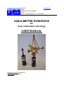
AQUA-METRE R300/R3000
for
local underwater metrology
USER MANUAL
Document reference: 0112-801-011
Date of issue: April 2, 2013
www.plsm.eu
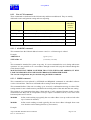
Document history
Document
number
Date of
issue
Modifications and comments
0112-801-000
June 14,
2004
June 30,
2004
September
5, 2004
October 15,
2004
January 12,
2005
Draft issue for review
0112-801-001
0112-801-002
0112-801-003
0112-801-004
0112-801-005
0112-801-006
0112-801-007
0112-801-008
0112-801-009
0112-801-010
0112-801-011
Correction of errata concerning mechanical offset of Base (727 mm
instead of 722 mm)
RS 232 interfaces opto-coupled, input supply range extended
Additional command CAPI for compensated capture (available since
firmware 3.04)
Description of AQUA-METRE R300 accessories including Surface
radio-modem buoy and interface Unit to PC.
Description of the special ROV Pointer.
Description of dam survey application using these new devices.
Minor corrections
January 12,
2005
New special ROV Pointer software version 3.05 with new functions.
May 09,
ROVNAV message added in the list of reported messages.
2005
Appendix added, pressure definition, pressure to depth conversion
explanation.
September - Correction of error concerning calculation of depth versus measured
19, 2005 pressure (chapter 12.2)
December New Base, Pointer R300 and ROV Pointer software version 3.06 with
dual capture capabilities and address range extension to 31.
9, 2005
New commands added:
- DCAPT,
- DCAPI,
- REQMOD
- SETMOD (to replace MODB CM only command)
New “DAT MODE” reported messages.
New CM command “MODECHO”.
October 15 Addition of R3000 units description
2006
October 10 - Modification of Radio-Modem buoy characteristics and charger,
- ROVPointer replaced by the versatile MiniPointer model
2008
Minor update
April 2,
2013
AQUA-METRE R300/R3000 User Manual
Doc. N° 0112-801-011
Page 2 /95
www.plsm.eu
SUMMARY
1
AQUA-METRE R300/R3000 presentation .......................................................................................6
1.1
1.2
1.3
2
AQUA-METRE R300/R3000 technical characteristics.................................................................10
2.1
2.2
3
Geometry associated with measurement ...........................................................................................10
System constrains and limitations .....................................................................................................11
2.2.1 Minimum depth........................................................................................................................11
2.2.2 Maximum depth.......................................................................................................................11
2.2.3 Acoustic path ...........................................................................................................................11
2.2.4 Operational area .....................................................................................................................12
2.2.5 Base stability and tilt ...............................................................................................................12
2.2.6 Base reversed (hanged from the surface)...........................................................................12
AQUA-METRE R300/R3000 potential mode of operation ...........................................................13
3.1
3.2
3.3
4
AQUA-METRE R300/R3000, basic configuration ............................................................................6
Accessories specific to the AQUA-METRE R300 .............................................................................7
AQUA-METRE R300/R3000 system configurations .........................................................................8
Basic configuration ...........................................................................................................................13
offshore flange to flange metrology configuration............................................................................14
Dam survey configuration (AQUA-METRE R300) .........................................................................15
AQUA-METRE R300/R3000 Base description..............................................................................18
4.1
4.2
Bloc diagram.....................................................................................................................................18
Base mechanical description.............................................................................................................19
4.2.1
Interferometric frame description ..............................................................................................20
4.2.2
AQUA-METRE R300 Base electronic housing description......................................................22
4.2.3
AQUA-METRE R3000 Base electronic housing description....................................................25
4.2.4
Interferometric frame and Base assembly (R300/R3000)..........................................................28
4.3
Base electrical interfaces description (R300/R3000)........................................................................29
4.4
Base switch on ..................................................................................................................................31
4.4.1
Base externally powered and connected to the serial link (CM mode) ......................................31
4.4.2
Base in acoustic remote mode ...................................................................................................32
5
AQUA-METRE R300, Pointer description ....................................................................................34
5.1
5.2
Bloc diagram.....................................................................................................................................34
Pointer mechanical description .........................................................................................................35
5.2.1
AQUA-METRE R300 Pointer electronic housing description ..................................................35
5.2.2
AQUA-METRE R3000 Pointer electronic housing description ................................................37
5.3
R300/R3000 Pointer electrical interface description ........................................................................39
5.4
Pointer switch on ..............................................................................................................................39
6
Surface buoy and surface interface description.........................................................................40
6.1
Surface interface description.............................................................................................................40
6.1.1
Surface Interface rear panel description ....................................................................................41
6.1.2
Surface Interface front panel description...................................................................................44
6.1.2.1
Video overlay activation .............................................................................................44
6.1.2.2
ROV interface activation.............................................................................................44
6.1.2.3
Radio-modem activation .............................................................................................45
6.1.2.4
Direct Cable link activation ........................................................................................45
6.2
Surface radio-modem buoy description ............................................................................................46
6.2.1
Surface Buoy activation.............................................................................................................48
6.2.2
Surface Buoy charge..................................................................................................................48
7
MiniPointer for AQUA-METRE R300.............................................................................................49
AQUA-METRE R300/R3000 User Manual
Doc. N° 0112-801-011
Page 3 /95
www.plsm.eu
7.1
7.2
7.3
7.4
7.5
8
MiniPointer electrical interfaces .......................................................................................................50
7.1.1
Hydrophone(s) Connector .........................................................................................................50
7.1.2
Interface & Power Connector ....................................................................................................52
MiniPointer mechanical characteristics ............................................................................................54
MiniPointer Installation on ROV......................................................................................................55
MiniPointer Charge ..........................................................................................................................55
ROV Pointer serial link protocol & commands ................................................................................57
7.5.1
Interface description ..................................................................................................................57
7.5.2
Monitor commands description .................................................................................................57
7.5.2.1
Monitor mode ..............................................................................................................57
7.5.2.2
List of specific ROV Pointer Monitor Commands .......................................................57
CM serial interface protocol (R300/R3000) ..................................................................................59
8.1
8.2
Interface description (serial port 0)...................................................................................................59
Monitor commands description ........................................................................................................59
8.2.1
Monitor mode ............................................................................................................................59
8.2.2
List of Monitor Commands........................................................................................................60
8.2.2.1
INIT jj command .........................................................................................................61
8.2.2.2
PING jj command........................................................................................................61
8.2.2.3
CAPT jj nn command ..................................................................................................61
8.2.2.4
CAPI jj nn command ...................................................................................................62
8.2.2.5
INCL jj command ........................................................................................................63
8.2.2.6
HEAD jj command ......................................................................................................64
8.2.2.7
VBAT jj command .......................................................................................................64
8.2.2.8
VEMI jj command .......................................................................................................65
8.2.2.9
TEMP jj command.......................................................................................................65
8.2.2.10
REQC0 jj command.....................................................................................................65
8.2.2.11
REQRT jj command.....................................................................................................65
8.2.2.12
REQMT jj command....................................................................................................66
8.2.2.13
PARAM jj command ....................................................................................................66
8.2.2.14
SETC0 jj command......................................................................................................66
8.2.2.15
SLEEP jj command .....................................................................................................66
8.2.2.16
SETRT jj command......................................................................................................67
8.2.2.17
SETVE jj command .....................................................................................................67
8.2.2.18
DCAPI jj nn command ................................................................................................67
8.2.2.19
DCAPT jj nn command ...............................................................................................69
8.2.2.20
SETMOD jj nn command ............................................................................................69
8.2.2.21
REQMOD jj command ................................................................................................69
8.2.3
List of CM command.................................................................................................................70
8.2.3.1
ADDCHG command....................................................................................................70
8.2.3.2
MODB command.........................................................................................................70
8.2.3.3
DISPO command.........................................................................................................71
8.2.3.4
LERR command...........................................................................................................71
8.2.3.5
MODECHO command ................................................................................................72
8.2.4
List of Report messages.............................................................................................................73
8.2.4.1
NOISE/DEMOD ERR report message ..................................................................74
8.2.4.2
INTERR: PNT (jj)report message ..........................................................................74
8.2.4.3
COORD: PNT (jj) report message.........................................................................75
8.2.4.4
PARAM: UNIT (jj) report message .......................................................................75
8.2.4.5
REQ: CAPT PNT (jj) FROM BASE (nn) report message ..................................76
8.2.4.6
REQ: PING (jj) report message .............................................................................76
8.2.4.7
REQ: INCLIN. (jj) report message ........................................................................76
8.2.4.8
REQ: HEAD (jj) report message ...........................................................................76
8.2.4.9
REQ: PARAM. (jj) report message........................................................................76
8.2.4.10
REQ: C0 (jj) report message ..................................................................................76
8.2.4.11
REQ: THRESHOLD (jj) report message ..............................................................77
8.2.4.12
REQ: V_EMI (jj) report message ..........................................................................77
AQUA-METRE R300/R3000 User Manual
Doc. N° 0112-801-011
Page 4 /95
www.plsm.eu
8.2.4.13
8.2.4.14
8.2.4.15
8.2.4.16
8.2.4.17
8.2.4.18
8.2.4.19
8.2.4.20
8.2.4.21
8.2.4.22
8.2.4.23
8.2.4.24
8.2.4.25
8.2.4.26
8.2.4.27
8.2.4.28
8.2.4.29
8.2.4.30
8.2.4.31
8.2.4.32
8.2.4.33
8.2.4.34
8.2.4.35
8.2.4.36
8.2.4.37
9
REQ: V_BAT (jj) report message ..........................................................................77
REQ: TEMP (jj) report message............................................................................77
REQ: REC. LEVEL (jj) report message ................................................................77
REQ: INIT (jj) report message ...............................................................................77
SET: C0 (jj) report message ...................................................................................78
SET: SLEEP (jj) report message............................................................................78
SET: THRESHOLD (jj) report message ...............................................................78
SET: V_EMI (jj) report message............................................................................78
DAT: INCLIN. (jj) report message ........................................................................79
DAT: HEAD (jj) report message ............................................................................79
DAT: C0 (jj) report message ..................................................................................80
DAT: DISPO (jj) & WARNING report message ..................................................80
DAT: DISPO (jj) & ERROR report message .......................................................81
DAT: MEAS. THRESHOLD (jj)… report message .............................................81
DAT: THRESHOLD (jj) report message ..............................................................81
DAT: V_EMI (jj) report message...........................................................................81
DAT: V_BAT (jj) report message ...........................................................................82
DAT: TEMP (jj) report message ............................................................................82
DAT: ROVNAV (jj) report message.......................................................................82
DAT: MODE (jj) report message ...........................................................................82
MSG: UNIT (jj) TILT>10° report message..........................................................84
MSG: UNIT (jj) CAPT. NO ANSWER° report message .....................................84
MSG: UNIT (jj) CAPT. CALC. ERROR report message ....................................84
MSG: UNIT (jj) CAPT. MULTIPATH ERROR report message ........................84
MSG: UNIT (jj) SLEEPING report message .......................................................84
System maintenance, build in tests .............................................................................................85
9.1
System maintenance..........................................................................................................................85
9.1.1
Fresh water rinsing ....................................................................................................................85
9.1.2
R300 Base/Pointer batteries charge ...........................................................................................85
9.1.3
R3000 Base/Pointer batteries charge .........................................................................................86
9.1.4
Base/Pointer connector maintenance R300/R3000....................................................................88
9.2
Build in tests, software update, Unit preparation… ..........................................................................89
9.2.1
Connection to a unit using the basic interface ...........................................................................89
9.2.2
Build In Tests (BIT) functions...................................................................................................91
9.2.3
Base or Pointer preparation .......................................................................................................91
9.2.4
Base or Pointer embedded software update ...............................................................................92
10
Specifications ..........................................................................................................................93
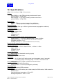
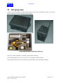
11
Carrying case ...........................................................................................................................94
12
Appendix ..................................................................................................................................95
12.1
12.2
Pressure definition ............................................................................................................................95
Pressure to water depth conversion...................................................................................................95
AQUA-METRE R300/R3000 User Manual
Doc. N° 0112-801-011
Page 5 /95
www.plsm.eu
1 AQUA-METRE R300/R3000 presentation
1.1 AQUA-METRE R300/R3000, basic configuration
The AQUA-METRE R300/R3000 is a local underwater positioning system based on an acoustical
interferometric scheme (mainly known as Ultra Short Base Line or USBL). It is particularly well
suited to accurate local 3D locating within the range of up to 150 metres (500 feet) from the reference
point (the Base). The system may be ROV operated and managed from the surface using acoustical
networking features. The AQUA-METRE R300 is dedicated to shallow water operation down to 300
metres like dam survey for instance, the AQUA-METRE R3000 has been designed for deep offshore
metrology. The two systems are compatible as far as electrical and mechanical interface are
concerned. The R3000 only differs by an aluminium housing instead of plastic and modified battery
charge scheme to avoid external plugs. They also share the same set of commands (monitor
commands and acoustic commands) Both may be operated using the AQUA-CAD software that
allows real time interface to Intellicad range of CAD tools.
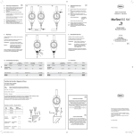
The simplest AQUA-METRE system configuration able to measure 3D coordinates underwater is
made of at least two main components:
-The measurement Base, which constitutes the local reference Cartesian coordinate system {0,0,0}),
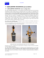
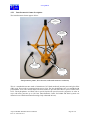
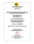
-At least one Pointer which replies to Base interrogations.
R300 regular Pointer (left) and R300 Base (right, frame connector unplugged)
Basically, the system is dedicated to 3D measurement of Pointer(s) location in the local coordinate
system(s) defined by the Base(s).
The AQUA-METRE R300/R3000 allows a very flexible system configuration made of several stand
alone units (a unit is a Base or a Pointer), all units communicate using acoustic messages, one unit
allows underwater system management from surface through a serial data-link (RS232 compatible).
This specific unit, that can be any Base or Pointer, is called the Communication Master (CM later in
this manual).
AQUA-METRE R300/R3000 User Manual
Doc. N° 0112-801-011
Page 6 /95
www.plsm.eu
1.2
Accessories
specific to the AQUA-METRE R300
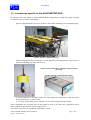
PLSM offers since end 2004 new AQUA-METRE R300 components to extends the system versatility
for shallow water operation, among them:
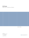
-
Specific light MiniPointer for survey by ROV, this Pointer including a precision depth gauge,
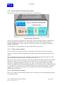
Pointer specific to light ROV survey
-
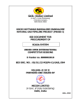
Surface radio-modem buoy to interface a remote hanged Base during shallow water survey of
underwater building (typically dam survey),
Surface radio-modem buoy with high capacity battery
pack (left)
Surface Interface with USB link (below)
-
A surface interface to PC that includes the radio-modem (to communicate with the surface
buoy) and moreover a video overlay,
A “T” frame with Cardan joint to stabilize a reverse Base hanged from the surface.
These components are described later in this manual as well as the dam survey application where
these components speed up the system set up and use.
Nota: these accessories are compatible with R3000 version.
AQUA-METRE R300/R3000 User Manual
Doc. N° 0112-801-011
Page 7 /95
www.plsm.eu
1.3 AQUA-METRE R300/R3000 system configurations
The AQUA-METRE R300/R3000 configuration is made of at least one unit that acts as the
Communication Master (CM) and is connected to the serial link up to the surface. With only one unit,
lets say a Pointer, it is possible to monitor heading and inclination of an underwater ROV or structure
for instance (in case of construction). More sophisticated configuration will require two Bases and
two Pointers like a full flange to flange connection metrology. The configurations are not limited and
may be adapted to specific needs (contact PLSM engineers to get advice about the best configuration
suited for your needs).
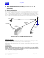
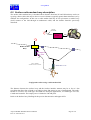
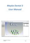
A typical ROV operated configuration could be as follow:
Remote
unit
#2
Remote
unit
#1
ROV’s umbilical
ROV
Power &
communication
interfaces
ROV
unit
(CM)
Remote
unit
#3
Remote
unit
#4
AQUA-METRE R300/R3000 underwater
parts
AQUA-METRE R300/R3000 ROV operated configuration (CM through ROV umbilical)
All units include dual axis inclinometer and fluxgate compass. Each Base can locate every Pointer or
another Base (specific feature of AQUA-METRE R300/R3000: a Base can act as a Pointer then be
interrogated).
It is then possible to manage the system from the surface and get measurement (3D location,
inclination, heading, temperature…) of every underwater unit using a simple communication terminal.
The list of commands, called Monitor Commands, are listed and described in following chapters.
PLSM also offers the AQUA-CAD software that allows system management through a friendly
Graphical User Interface (GUI) and real-time interface to popular CAD software in order to get the
best environment for metrology class survey. The AQUA-CAD software is described in a separate
manual.
AQUA-METRE R300/R3000 User Manual
Doc. N° 0112-801-011
Page 8 /95
www.plsm.eu
Survey computer (PC)
Serial com
Demux
ROV’s umbilical
COM
INTELLICAD
software
AQUA-CAD
software
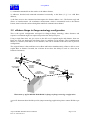
Surface system synoptic using AQUA-CAD software
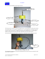
The AQUA-METRE R300 may also be simply operated from the surface, in this case the CM unit is
just hanged from a taut wire or pier wall and the serial link could be a direct cable (up to 100 metres)
or a licence free radio-modem.
This configuration appears below:
Surface configuration using a radio-modem buoy, USB interface (with radio-modem, video
overlay,…) and AQUA-CAD software.
This AQUA-METRE R300 configuration is typically used for metrology of submerged building like
bridge, dam, pier,…
The dam survey application is described later in this manual as a good sample of AQUA-METRE
versatility and ease of set up and use.
AQUA-METRE R300/R3000 User Manual
Doc. N° 0112-801-011
Page 9 /95
www.plsm.eu
2 AQUA-METRE R300/R3000 technical
characteristics
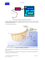
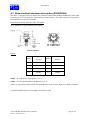
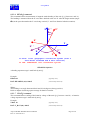
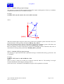
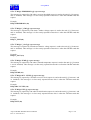
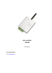
2.1 Geometry associated with measurement
The system measures the 3D coordinates of Pointer
hydrophone in a local Cartesian coordinate system.
This local Cartesian coordinate system being
associated with the interferometric frame. The two
angles are measured using a 3D interferometric
scheme and distance is measured using transit time
assuming a measured celerity (celerity is measured
by each Base on demand and can also be set by user
to a specific value).
A biaxial inclinometer measures unit inclination up
to +/-20° with an accuracy better than 0.1°.
The origin of the local coordinate system of a
specific Base is the top hydrophone.
θ
M
Z
d
Y
{0,0,0}
φ
X
The picture on the right shows the coordinate system
associated with the interferometric frame:
A point M is given by:
-the distance d from the origin,
-the azimuth angle φ in the horizontal plane,
-the elevation angle θ from vertical.
(spherical coordinate system)
A locking pin allows rotation indexation when the
frame is screwed on the Base housing. This pin
indexation is associated with the X axis (positive
direction) and is also aligned with the bottom
mechanical interface (see chapter describing Base
and Pointer mechanical housing).
Rotation lock. pin
Warning:
The precise geometry of the interferometric frame guarantees the accuracy of the system. It is
very important to prevent frame from being hurt. Any deformation of the frame may definitely
affect the accuracy by introducing bias error.
AQUA-METRE R300/R3000 User Manual
Doc. N° 0112-801-011
Page 10 /95
www.plsm.eu
2.2 System constrains and limitations
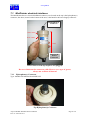
2.2.1 Minimum depth
The system required at least 5 meters depth
to operate well; in this case, the
interferometric frame must be set up at mid
depth (i.e. 2.5 meters).
2.5 meters
minimum
If operated in no more than 5 meters deep,
the accuracy may be affected by severe
multipath environment when distance from
Base to Pointer exceeds 30 meters. To
operate well up to 150 meters, the system
requires at least 20 meters deep.
BASE
2.5 meters
minimum
1 meter
minimum
When measuring coordinates near seafloor,
make sure that the Pointer is operated with
a minimum vertical offset of 1 meter.
2.2.2 Maximum depth
The R300 maximum operating depth is 300 metres.
The R3000 maximum operating depth is 3000 metres (maximum hydrostatic pressure 350 bars).
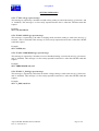
2.2.3 Acoustic path
To operate, the AQUA-METRE R300/R3000 requires a direct acoustic path between the Base and the
Pointer (this is an advantage compared to long baselines system which requires several free paths). A
mask may affect the accuracy and/or stability of the measures, or may simply vanish the acoustic
wave.
The following rule of thumb must be followed: keep at least one meter and a half clear from the direct
virtual line between the Base and the Pointer as described below:
BASE
Hmi n > 1. 5met r e
POI NTER
Seaf l oor
Base to Pointer acoustic path requirement
This value clearance distance is obviously Base to Pointer distance dependant.
The choice of the Base location is one of the most critical steps of the system set up.
AQUA-METRE R300/R3000 User Manual
Doc. N° 0112-801-011
Page 11 /95
www.plsm.eu
2.2.4 Operational area
Warning: the interferometric frame does not allow proper measurement in the blind area described
below:
50cm
Operational
area
Blind
area
2.5m
min
2m
Description of the operational and blind area
The measurements taken in this area may be affected by inaccuracy.
The maximum recommended distance from the Base is 150 meters (300 metres area diameter) even if
the system may still operate up to 200/250 meters in case of good acoustic propagation conditions.
When using the system, make sure that the acoustic path conditions described before are met.
2.2.5 Base stability and tilt
If the measurement have to be gravity referenced (meaning that local Z axis is vertical), the initial
Base tilt setting must be lower than 15° from vertical in order to allow the compensation by internal
inclinometer.
The dynamic oscillation of the Base must be limited to +/-2 cm (peak to peak) and the maximum
frequency of oscillation limited to 1 Hertz.
If it is not expected to reference the measurement to gravity and then work in pure relative mode, then
there is no Base position constraint. But Base stability will directly affect the final accuracy and must
be compensate by external MRU (Motion Reference Unit) if necessary.
2.2.6 Base reversed (hanged from the surface)
It is also possible to get gravity referenced measurement (meaning that local Z axis is vertical) when
the Base is reversed and hanged from the surface, however, the initial Base axis tilt setting must again
be lower than 15° from vertical in order to allow the compensation by internal inclinometer. A
specific Base parameter has to be set in order to indicate the reverse position (see description later in
this manual), then the internal coordinate compensation routine compute the final coordinate with Z
axis being always vertical.
The dynamic oscillation of the Base remains limited to +/-2 cm (peak to peak) and the maximum
frequency of oscillation limited to 1 Hertz. PLSM offers a specific frame structure with a Cardan joint
in order to attenuate the oscillation keeping the rotation unchanged.
AQUA-METRE R300/R3000 User Manual
Doc. N° 0112-801-011
Page 12 /95
www.plsm.eu
3 AQUA-METRE R300/R3000 potential mode of
operation
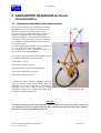
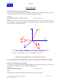
3.1 Basic configuration
This is the simplest configuration closed to the current AQUA-METRE D100 (diver operated system)
way of working. The Base is attached at the top of a mast (height being about 2 metres), which lies on
seabed. A Pointer is attached to the ROV and connected to the umbilical communication channel, it
will act as the Communication Master (CM). One or several other Pointers are spread on the working
field at strategic locations depending on the type of survey (to be defined by the survey engineer).
ZL
YL
Pointer #1
XL
Acoustic measurement #1
R1, θ1, ϕ1
Communication and
acoustic measurement
(R3, θ3, ϕ3)
Data link through the
ROV umbilical
Spy Pointer :
communication/system
control
Acoustic measurement #2
R2, θ2, ϕ2
ROV
Pointer #2
Illustration of Basic AQUA-METRE R300/R3000 configuration
Initialisation of the units:
The remote units will be switch before dive and remain in sleeping mode. The first step is to wake up
every unit by sending “PING” commands (refer to monitor command chapter).
Then, each unit will be initialised using “INIT” command, and especially the Base that will measure
sound celerity.
After initialisation:
Typical command executed in this configuration will be the “CAPT jj nn” command (CAPTURE
command where nn stands for Base address and jj for the Pointer address, refer to later chapter for
detailed presentation of this command), this command will give access to coordinates measurement of
Pointer with reference to the Base interferometric frame.
In this configuration, the CAPTURE command will be executed as follow:
AQUA-METRE R300/R3000 User Manual
Doc. N° 0112-801-011
Page 13 /95
www.plsm.eu
1) command transmitted from the surface to the Master Pointer,
2) addresses decoded and command transmitted acoustically to the Base (if “jj” is a valid Base
address),
3) the Base receives the command and interrogates the Pointer address “nn”, The Pointer reply and
allows an interferometric 3D coordinates measurement, which is transmitted back to the Master
Pointer, then back to the surface through the umbilical communication channel.
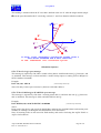
3.2 offshore flange to flange metrology configuration
This is the typical configuration envisaged for flange-to-flange metrology where distances and
respective orientation angles are required to produce the final spool piece.
Using a single Base does not give access to the full set of required angles and distance, then two
Bases are used, one attached to each flange, Base #1 and Base #2 for instance. The Communication
Master is a Pointer (with address #3 for instance) and will be attached to the ROV like in previous
configuration.
The original feature is that each Base acts as Base and Pointer simultaneously (a Base is able to act as
regular Base or Pointer if needed, but a Pointer do not have the ability to work as a base due to
hardware limitation).
Base #1
Master/Slave
α1
θ1
Acoustic
measurement
#1
Communication
and acoustic
measurement
Data link through the
ROV umbilical
L
Acoustic
measurement
#2
θ2
Spy Pointer :
System Management
Communication, Control
Communication
and acoustic
measurement
α2
Base #2
Master/Slave
ROV
Illustration of AQUA-METRE R300/R3000 in flange-to-flange metrology configuration
A specific document described the spool & jumper metrology application (please contact PLSM to get
it).
AQUA-METRE R300/R3000 User Manual
Doc. N° 0112-801-011
Page 14 /95
www.plsm.eu
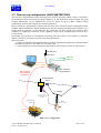
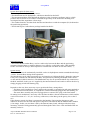
3.3 Dam survey configuration (AQUA-METRE R300)
This specific configuration provides metrology class 3D ROV positions within a range of 150 meters
all around the acoustic Base reference point. Thanks to its full stand-alone wireless design, the small
acoustic MiniPointer can be installed very easily on almost all types of ROV without vehicle
modification, and basically requests no electrical connexion.
ROV positions are permanently computed into the Base from acoustical signals exchanged between
the Base and the MiniPointer, then transmitted from the Base to the positioning system computer via a
simple cable or optionally via the radio link. By running the P.L.S.M. AQUA-CAD software, ROV
positions are displayed in real time on the operator’s screen while simultaneously processed by a
CAD software.
Generating only one Base to Transponder acoustical path, the system is less sensible to reflection.
While a two unit system also means a fast and easy deployment.
Options include:
- A licence free Radio-modem link for Base to onshore equipments long distance communications
(868 MHz for Europe or 915 MHz for CANADA/USA),
- A video module to overlay position data into the ROV video images ( NTSC or PAL format),
UHF ANTENNA
UHF CABLE
VIDEO IN
VIDEO OUT
USB CABLE
AQUA-METER
USB INTERFACE
RS232 LINK TO
ROV POINTER
(OPTIONAL)
RADIO-MODEM
BUOY
« T » FRAME
10 to 200m
UNDERWATER
CABLE
MiniPointeur
R300
R300
BASE UNIT
SURVEY
ROV
Dam survey configuration
AQUA-METRE R300/R3000 User Manual
Doc. N° 0112-801-011
Page 15 /95
www.plsm.eu
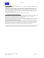
System description for dam survey:
The basic system includes four components:
- The MiniPointer and its hydrophone, which must installed on the ROV.
- The measurement Base which defined the reference point (Cartesian coordinate {0,0,0}) which
position must be chosen in accordance with both the geometry of the underwater building to be
investigated and the Aqua-Metre 150 m range.
- The onshore Interface Unit that feeds the Base and interfaces it with the computer (PC) dedicated to
the positioning operations.
- The PLSM AQUA-CAD software package installed in this PC
MiniPointer installed on a light survey class ROV
Optional units are:
- The Surface Radio-modem Buoy, used as a radio relay between the Base and the positioning
computer when the Base to computer distance is too long for a cable link (radio: UHF 869 MHz
licence free band for Europe, other frequencies available like 915 MHz for US and Canada,…),
System set-up:
The MiniPointer must be mechanically installed, such as its hydrophone remains unmasked and always
“visible” from the Base during all the operations.
The MiniPointer can be either powered by its own batteries or fed from the ROV, through a connector
It may also communicate and transmit the ROV navigation data (Heading and Depth) to the surface
via the umbilical (RS232 interface). The MiniPointer may also be operated without any connection to
the ROV umbilical, in this case it is supplied by the internal batteries and switch on before the dive by
simply plugging an ON/OFF dummy plug.
Depends on the case, there are many ways to position the Base, among others:
- The Base can be installed on a mast, and then the assembly is suspended in mid water attached to
a cable taut between the banks, or suspended to a mast horizontally plugged into the building, etc.
- The mast/ Base assembly may also be plugged into a concrete bloc lying on the firm bottom….
No tuning level mechanism is necessary since the Base includes a biaxial inclinometer, which enables
vertical corrections of +/-15° (0.1° accuracy) of the mast, so the Base gets the gravity axis as the Zaxis.
If the distance permits, the Base is connected to the Interface Unit using the data/power cable,
otherwise one must use the radio link option composed of the Beacon and the Modem Radio module
(1 km range). In this case, the Base is fed by the Beacon battery bank, which provides three days
autonomy, instead of being permanently powered through the cable. Note: Cable and Radio links are
mutually exclusive.
AQUA-METRE R300/R3000 User Manual
Doc. N° 0112-801-011
Page 16 /95
www.plsm.eu
Details of operation:
- The PC’s operator using the AQUA-CAD software commands a Transponder acoustic interrogation
from the Base.
- The Base executes the command, measures the distance, the vertical and horizontal angles (3D
interferometric scheme) and sends the results back to the PC through the data link (cable or radio).
- The AQUA-CAD software running on the PC automatically transforms the local coordinates
received into the global coordinate system associated with the building, and updates the AutoCAD
document and the video overlay.
- This process is automatically iterated until user pause or stop the system.
Local to absolute coordinate system calibration:
Measuring the acoustic coordinates of two reference points named pivot and lever, these points being
defined in the final coordinate system, performs the transformation from the local acoustic
coordinates into an absolute cartographic coordinate system.
The absolute coordinates of these two reference points must be already known and identified in the
CAD drawing and directly peek by the user from the CAD software (thanks to the real time CAD
driver layers with bi-directional data exchanges).
Then, the calibration just consists of moving successively the ROV to each reference point, pick up
their respective positions in the CAD drawing and wait for the acoustic measurement completion.
During dam survey for instance, the reference points are often chosen along the seal between two
concrete blocks which position is well known (critical vertical lines to be surveyed).
The calibration takes few minutes and remains valid until the next Base translation. It can be saved in
a configuration file in order to recall it when starting in the morning in order to be quickly ready.
.
AQUA-METRE R300/R3000 User Manual
Doc. N° 0112-801-011
Page 17 /95
www.plsm.eu
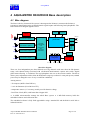
4 AQUA-METRE R300/R3000 Base description
4.1 Bloc diagram
The Base is the key element of the system, it interrogates the Pointer(s), measures the Pointer(s)
response to interrogation using an interferometric signal capture scheme using four hydrophones. The
Base internal bloc diagram appears below:
3D
Compass
Power
Emitter
2 axis
Inclinometer
RX0/TX0
Channel #1 receiver
(Pass band filter, amplifier,…)
µController
Hydrophone
#1
Channel #2 receiver
(Pass band filter, amplifier,…)
CAPTURE/
Communication
UNIT
Channel #3 receiver
(Pass band filter, amplifier,…)
(transit time &
phase
measurement,
demodulator)
Hydrophone
#2
RS232
#0
RX1/TX1
RS232
#1
Real
Time
Clock
(RTC)
Hydrophone
#3
Bat T°
sensor
Power & charge
management
Channel #4 receiver
(Pass band filter, amplifier,…)
Hydrophone
#4
Ext. supply
Internal
Accumulator
ON/OFF Charge supply
Base bloc diagram
There are four independent pass band filtered receiving channels with more than 80 dB dynamic
range, each channel being associated with a dedicated interferometric capture unit (with a digital
phase-metre allowing 1° resolution) The top hydrophone also act as the acoustic emitter. The driver
allows power adjustment with at least 40 dB dynamic range up to about 25 watts peak power (emitted
power may be changed in case of very reverberant conditions).
Among sensors:
- 3D compass (M3XA from PNI Inc),
- 2 axis inclinometer (SCA600 from VTI),
- temperature sensor (1°C accuracy) mainly used for batteries charge,
- Real Time Clock (RTC) with better than 20 ppm drift.
A 12 MIPS microcontroller manage the whole Base system. A 2 MB flash memory holds the
embedded software and calibration data.
The embedded software is fully field upgradeable using a standard PC and the RS232 serial link or
infrared interface.
AQUA-METRE R300/R3000 User Manual
Doc. N° 0112-801-011
Page 18 /95
www.plsm.eu
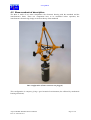
4.2 Base mechanical description
The Base is made of two main components: the electronic housing with the masthead and the
interferometric frame. These two components have to be assembled before operation, the
interferometric frame being simply screwed on the top of the masthead
Base configuration (Frame connector not plugged)
This configuration is compact, giving a good acoustical environment (less affected by mechanical
housing reflections).
AQUA-METRE R300/R3000 User Manual
Doc. N° 0112-801-011
Page 19 /95
www.plsm.eu
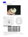
4.2.1
Interferometric frame description
The interferometric frame appears below:
Top
Hydrophone
3x bottom
Hydrophone
U/W frame
connector
Indexation
rotation pin
Interferometric frame, 3D CAD view (cable and connector not drawn)
This is a tetrahedral structure made of aluminium (7075 hard anodised) junction parts and glass fibre
(FR5) rods. These rods are cemented using epoxy resin. The four hydrophones are over moulded with
polyurethane resin. The mould shape has been studied to prevent direct hurt to piezo-ceramic tube
faces. The hydrophones are filled with a special liquid with special acoustic properties in order to
cope with static pressure up to 350 bars (Interferometric frame for R3000 and R300 systems are
identical even if R300 mechanical housings only withstand 30 bars).
AQUA-METRE R300/R3000 User Manual
Doc. N° 0112-801-011
Page 20 /95
www.plsm.eu
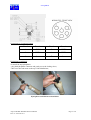
The overall dimensions appear below:
Interferometric Frame drawing
The maximum height is 414 mm and radius 199 mm.
Weight is about 1.4 kg+/-0.1 kg (including cables and connector)
AQUA-METRE R300/R3000 User Manual
Doc. N° 0112-801-011
Page 21 /95
www.plsm.eu
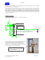
4.2.2
AQUA-METRE R300 Base electronic housing description
The electronic mechanical housing appear below:
Indexation pin
Interferometric frame thread (M10)
Interferometric frame base plate
Interface connector
Interferometric frame connector
Top cap with upper sleeve
Main housing (PVC)
Bottom aluminium sleeve
Bottom housing with indexation
pin aligned with X axis
Infrared interface window
The electronic housing parts are made of plastic or hard anodised 7075 T6 aluminium. The top cap
supports the two connectors (description hereafter), one being connected to the interferometric frame,
AQUA-METRE R300/R3000 User Manual
Doc. N° 0112-801-011
Page 22 /95
www.plsm.eu
the other to the ROV interface or to a dummy plug in case of an acoustic remote unit. It also support
charge connectors (316L stainless steel).
Simply plugging the charge adaptor charges the batteries. Batteries charge is fully managed by
internal processor (switched on when plugging the batteries charger) and switched to steady charge
state at the end of charge. The bottom housing also acts as the mechanical interface for field and/or
ROV installation. This interface is centered and an indexing hole lock the rotation allowing a perfect
known offset from the interferometric frame then the local Cartesian coordinate system associated
with the measurements.
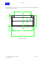
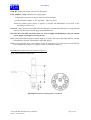
Mechanical interface:
Drawing of the mechanical interface cross section appears below:
Referenc
e
surface
{0,0,0} origin
(top frame
hydrophone)
727 mm
The origin of local coordinate system associated with the Base
and Interferometric frame is located 727 mm above the
reference surface. In other word, the reference surface is
located at z= -0.727 m according to origin of local coordinate
system associated with acoustic measurements.
727 mm
727 mm from reference surface of mechanical
interface to the centre of the top hydrophone
(origin of measurements)
AQUA-METRE R300/R3000 User Manual
Doc. N° 0112-801-011
Page 23 /95
www.plsm.eu
A bottom aluminium sleeve is also delivered in order to facilitate mechanical interface production.
This sleeve drawing appears below:
Bottom sleeve drawing
AQUA-METRE R300/R3000 User Manual
Doc. N° 0112-801-011
Page 24 /95
www.plsm.eu
4.2.3
AQUA-METRE R3000 Base electronic housing description
The AQUA-METRE R300 mechanical housing appear below:
Indexation pin
Interferometric frame thread (M10)
Interferometric frame base plate
Interface connector
Interferometric frame connector
Top cap with upper sleeve
Main housing (hard anodised
aluminium)
Bottom sleeve thread for
mechanical interface
The main differences compared to R300 version are:
-
hard anodised aluminium housing instead of plastic,
-
plastic (DELRIN) sleeves instead of aluminium,
-
no specific charge connector (charge through interface connector),
-
no led indicator nor infrared interface.
The electronic housing parts are made of hard anodised 7075 T6 aluminium. The top cap supports the
two connectors (description hereafter), one being connected to the interferometric frame, the other to
the ROV interface or to a dummy plug in case of an acoustic remote unit.
The bottom housing also acts as the mechanical interface for field and/or ROV installation. This
interface is centered and an indexing hole lock the rotation allowing a perfect known offset from the
interferometric frame then the local Cartesian coordinate system associated with the measurements.
AQUA-METRE R300/R3000 User Manual
Doc. N° 0112-801-011
Page 25 /95
www.plsm.eu
R3000 Mechanical interface:
Drawing of the mechanical interface cross section appears below (fully compatible with R300 Base
version):
Referenc
e
surface
{0,0,0} origin
(top frame
hydrophone)
727 mm
The origin of local coordinate system associated with the Base
and Interferometric frame is located 727 mm above the
reference surface. In other word, the reference surface is
located at z= -0.727 m according to origin of local coordinate
system associated with acoustic measurements.
727 mm
727 mm from reference surface of mechanical
interface to the centre of the top hydrophone
(origin of measurements)
AQUA-METRE R300/R3000 User Manual
Doc. N° 0112-801-011
Page 26 /95
www.plsm.eu
A bottom plastic sleeve is also delivered in order to facilitate mechanical interface production. This
sleeve drawing appears below:
R3000 bottom sleeve drawing
Nota: this R3000 bottom sleeve is different from the R300 version but may be used for R300
housing.
AQUA-METRE R300/R3000 User Manual
Doc. N° 0112-801-011
Page 27 /95
www.plsm.eu
4.2.4
Interferometric frame and Base assembly (R300/R3000)
Place the frame base plate over the frame rest (A), and turn it until the locating pin is aligned with its
locating hole, then lock with the main screw (B). Check that the frame is properly installed by looking
for clearance. Any clearance in this area may be detrimental for the measurement accuracy. Then plug
the electrical male connector on the female socket located on the base housing (full proof design).
(B) Frame screw
Frame base plate
AQUA-METRE R300/R3000 User Manual
Doc. N° 0112-801-011
Page 28 /95
www.plsm.eu
4.3 Base electrical interfaces description (R300/R3000)
The Base is equipped with two underwater connectors (IMPULSE MCBH-8 bulkhead), both located
at the top cap. One is dedicated to interferometric frame interface. The other connector being used for
ROV interface and ON/OFF functions.
Interferometric frame connector (JP1) description:
Type: MCBH-8-FS type bulkhead from Impulse
Female bulkhead
Pinout:
Pin
number
Signal
function
Pin
number
Signal
function
1
GND1
5
GND2
2
HYD1
6
HYD2
3
GND4
7
GND3
4
HYD4
8
HYD3
HYD1…4 : connection to hydrophone #1 to 4
GND1…4: return ground path for hydrophone #1 to 4
(There are separated ground path for each hydrophone in order to allow high cross channel isolation)
Use MCIL-8-MP connector from Impulse for interface cable.
AQUA-METRE R300/R3000 User Manual
Doc. N° 0112-801-011
Page 29 /95
www.plsm.eu
Interface connector (JP2) description:
Type: MCBH-8-FS type bulkhead (see description and comment above)
Pinout:
Pin
number
Signal
function
Pin
number
Signal
function
1
GND_RS
5
GND
2
RX_RS0
6
ON/OFF
3
TX_RS0
7
TX_RS1
4
EXT_SUPPLY
8
RX_RS1
RX_RS0, TX_RS0 : RX/TX signals of main serial port (port 0), RS232 electrical level (MAX232
interface), this serial port is internally opto-coupled to ensure proper isolation,
RX_RS1, TX_RS1 : RX/TX signals of ancillary serial port (port 1), RS232 electrical level (MAX232
interface), this serial port is internally opto-coupled to ensure proper isolation,
NOTE: RX_RS0 or RX_RS1 are downlink and must be connected to TX line of the PC, and
TX_RS0 or TX_RS1 as uplink to the RX line of the PC (cross Rxi/Txi between two equipment).
GND_RS: signal return path for both serial ports,
EXT_SUPPLY: external supply used to powered the Base with following characteristics:
- Voltage level between 12 and 34 Volts (24 Volts recommended),
- Maximum current: 300mA (12V input),
When external power is applied, it automatically switches the Base on.
ON/OFF: input signal used to switch the Base on or off, when floating Base is switched off, must be
grounded to switch the Base on (driven by open drain, open collector or switch for instance).
R3000 specific: when external power and ON/OFF signal are active simultaneously, then the Base
enters charge mode, this is done automatically using the R3000 charger interface.
Use MCIL-8-MP connector from Impulse for interface cable.
Important feature : since the connector are not mechanically differentiated, pinout of respective
bulkhead have been chosen in order to avoid any damage in case of connector crossing.
Acoustic remote mode: if the unit is not connected to the ROV interface, a dummy plug will be used
to switch it on before the dive (this plug simply grounds ON/OFF pin and protects all the pins from
sea water). When switched on, the unit performs self-tests and emits an audible tone using the top
hydrophone and enter a sleeping mode waiting for incoming acoustic “PING” wake-up message.
Power consumption in sleeping mode is lowered allowing several days of autonomy.
AQUA-METRE R300/R3000 User Manual
Doc. N° 0112-801-011
Page 30 /95
www.plsm.eu
4.4 Base switch on
4.4.1
Base externally powered and connected to the serial link (CM mode)
If the Base is the Communication Master unit and then externally powered, simply apply power
supply to switch it on.
If already connected to a terminal emulator, the unit will then output the following messages:
Icharge= 0.0
Pointeur AQUA-METRE R3000 (DISPO= 032)
Version Logiciel= 302
Version Materiel= 202
Numéro série= 101
Mode= 000
Adresse= 10
Mode= 0
CM: TYPE ? TO ENTER MONITOR MODE
Then, type a question mark rapidly (you have about 4 seconds) in order to enter monitor mode.
Before, it will activate the build-in surface tests with the following messages being displayed:
Basse tension émission= 7.75
Test du DAC et comparateurs
Resultat test DAC= 0
Mesure du seuil de reception
Seuil Voie 1: 0.51 V
Seuil recepteur final= 1.00 V
Calibration du recepteur en phase
Mesure Cap
Cap mesure= 263.8 deg
Celerite par defaut= 1500 m/s
Tension batteries= 7.49
Fin de la calibration/initialisation
Code erreur=
Code alerte=
0
0
MONITOR MODE (CM)
*
The unit is then in monitor mode and able to execute monitor commands (see chapter hereafter).
AQUA-METRE R300/R3000 User Manual
Doc. N° 0112-801-011
Page 31 /95
www.plsm.eu
Before entering in monitor mode, the Base will beep two times if initialisation successful, or just once
if error or warning occurs. These beeps are mainly dedicated to switch on in remote mode with
dummy plug (see next chapter).
If you did not enter monitor mode directly by typing the question mark when prompted, the unit will
enters sleeping mode after initialisation. A wake up windows occurs for 2 seconds every 60 seconds
and the following message is send to announce the wake up window:
….
Code alerte=
0
MSG: UNIT (12) SLEEPING
(first sleeping period of 30 seconds)
CM: WAKE UP (2s)
(output by unit, then type “?” to exit sleeping)
MONITOR MODE (CM)
*
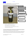
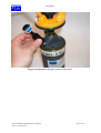
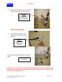
4.4.2
(monitor mode)
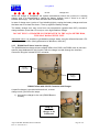
Base in acoustic remote mode
If the Base is expected to work in acoustic remote mode:
- make sure it is well charged,
- just before survey, plug the dummy on/off connector in the interface bulkhead,
- wait until unit beeps: two short beeps means initialisation is successful and unit is then in sleeping
mode, one medium (about 1 second) beep means warning encountered and a long beep means error(s)
occurs.
Check the unit if warning or error occurs.
On/Off dummy plug (for remote acoustic mode)
AQUA-METRE R300/R3000 User Manual
Doc. N° 0112-801-011
Page 32 /95
www.plsm.eu
Plugging On/Off dummy plug (for remote acoustic mode)
AQUA-METRE R300/R3000 User Manual
Doc. N° 0112-801-011
Page 33 /95
www.plsm.eu
5 AQUA-METRE R300, Pointer description
5.1 Bloc diagram
The Pointer is the basic unit used to receive interrogations from Base(s) and respond to them, The
main functionality of this unit is to reply to Base interrogations.
The Pointer internal bloc diagram appears below:
3D
Compass
Power
Emitter
2 axis
Inclinometer
RX0/TX0
Receiver
(Pass band filter, amplifier,…)
RS232
#0
µController
Hydrophone
RX1/TX1
RS232
#1
CAPTURE/
Communication
UNIT
Real
Time
Clock
(RTC)
(phase
measurement,
demodulator)
Bat T°
sensor
Power & charge
management
Ext. supply
Internal
Accumulator
ON/OFF Charge supply
Pointer bloc diagram
This bloc diagram is similar to the Base, but there is only one pass band filtered receiving channel
with more than 80 dB dynamic range, this channel being associated with a dedicated capture unit
(with a digital phase-metre allowing 1° resolution) The single hydrophone also act as the acoustic
emitter. The driver allow power adjustment with at least 40 dB dynamic range up to about 25 watts
peak power (radiated power is automatically reduced depending on distance between Base and
Pointer, after first measurement obviously).
Among sensors:
- 3D compass (M3XA from PNI Inc),
- 2 axis inclinometer (SCA600 from VTI),
- temperature sensor (1°C accuracy) mainly used for batteries charge,
- Real Time Clock (RTC) with better than 20 ppm drift (to be confirmed).
A 12 MIPS micro controller manages the whole Base system. A 2 MB flash memory holds the
embedded software and calibration data, and also gives the capacity to store measurement data if
needed.
The embedded software is field upgradeable using a standard PC and the RS232 serial link.
AQUA-METRE R300/R3000 User Manual
Doc. N° 0112-801-011
Page 34 /95
www.plsm.eu
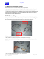
5.2 Pointer mechanical description
The Pointer mechanical housing is very similar to the Base. The single hydrophone just replaces the
small Frame mast. A specific hydrophone mast including a spring prevents the hydrophone from
being hurt. There is also a polyurethane over-moulded protection to protect it.
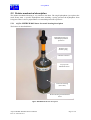
5.2.1
AQUA-METRE R300 Pointer electronic housing description
The Pointer is described below:
Hydrophone with over
moulded polyurethane
protection
Stainless steel
flexible spring
Interface connector
Top cap with
aluminium sleeve
Electronic housing
(PVC tube)
Bottom housing with aluminium
sleeve
AQUA-METRE R300 Pointer description
AQUA-METRE R300/R3000 User Manual
Doc. N° 0112-801-011
Page 35 /95
www.plsm.eu
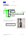
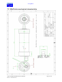
Mechanical interface:
Drawing of the mechanical interface cross section appears below:
Referenc
e
surface
{0,0,0} origin
(Pointer
hydrophone)
430 mm
The actual point of measurement associated with the Pointer
is located 430 mm above the reference surface.
430 mm
430 mm from reference surface of mechanical
interface to the centre of the Pointer
hydrophone (actual point of measurements)
AQUA-METRE R300/R3000 User Manual
Doc. N° 0112-801-011
Page 36 /95
www.plsm.eu
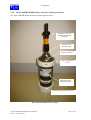
5.2.2
AQUA-METRE R3000 Pointer electronic housing description
The AQUA-METRE R3000 Pointer description appears below:
Hydrophone with over
moulded polyurethane
protection
Stainless steel
flexible spring
Interface connector
Top cap with plastic
sleeve
Electronic housing
(aluminium tube)
Bottom housing with plastic sleeve
AQUA-METRE R3000 Pointer description
AQUA-METRE R300/R3000 User Manual
Doc. N° 0112-801-011
Page 37 /95
www.plsm.eu
Mechanical interface:
Drawing of the mechanical interface cross section appears below:
Referenc
e
surface
{0,0,0} origin
(Pointer
hydrophone)
430 mm
The actual point of measurement associated with the Pointer
is located xxx mm above the reference surface.
430 mm
It is a bit different than R300 version.
430 mm from reference surface of mechanical
interface to the centre of the Pointer
hydrophone (actual point of measurements)
AQUA-METRE R300/R3000 User Manual
Doc. N° 0112-801-011
Page 38 /95
www.plsm.eu
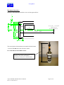
5.3 R300/R3000 Pointer electrical interface description
The Pointer is equipped with only one underwater connectors (IMPULSE MCBH-8 bulkhead),
located on the top cap. This connector (8 pins connector) being used for ROV interface and ON/OFF
functions.
Interface connector description:
Identical to Base interface connector, please refer to chapter describing Base connector.
Acoustic remote mode: if the unit is not connected to the ROV interface, a dummy plug will be used
to switch it on before the dive (this plug simply grounds ON/OFF pin and protects all the pins from
sea water). When switched on, the unit performs self-tests and emit an audible tone using the top
hydrophone and enter a sleeping mode waiting for incoming acoustic “PING” wake up message.
Power consumption in sleeping mode is lowered allowing several days of autonomy.
5.4 Pointer switch on
Identical to Base, please refer to chapter dedicated to Base switch on
AQUA-METRE R300/R3000 User Manual
Doc. N° 0112-801-011
Page 39 /95
www.plsm.eu
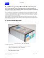
6 Surface buoy and surface interface description
The surface buoy and surface interface are optional but useful devices when operating the CM
directly from the surface. They are dedicated to shallow water then more oriented to AQUA-METRE
R300 applications even if they are compatible with R3000 version due to the same electrical and
mechanical interface between these two versions.
The surface interface is a powerful device that includes a licence free radio-modem (to operate the
CM up to 2/3 km away from the PC), a direct cable interface (to operate the CM up to 200 metres
from the PC), a ROV Pointer interface and a video overlay (PAL or NTSC on demand). This is the
perfect tool for light survey operation by ROV.
The surface buoy is required when direct cable link with the CM is no allowed or not easy due to
distance. It includes the licence free radio-modem as well as a high capacity battery pack in order to
provide autonomy of one week.
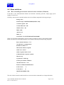
6.1 Surface interface description
The Surface Interface is a versatile unit enclosed in a small 170x100x50 mm aluminium housing.
Surface Interface for AQUA-METRE R300
It includes four functions:
-
A radio-modem unit to interface with Surface buoy (see next chapter),
-
A video overlay module (PAL or NTSC on demand),
-
An interface to ROV using RS232 or RS 485,
-
A direct cable interface to CM unit.
AQUA-METRE R300/R3000 User Manual
Doc. N° 0112-801-011
Page 40 /95
www.plsm.eu
These functions are interfaced to the host user PC using a USB to serial COM port converter, then
each function may be addressed independently through virtual Windows COM ports, then accessible
with a simple terminal emulator up to the AQUA-CAD software from PLSM. User can also build is
own interface or adapt it to is current ROV environment.
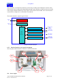
The Surface Interface synoptic appears below:
10-36V
DC
Power Converter
USB to
PC
USB interface
COM
#0
COM
#1
USB to
Serial COM
Port (4)
converter
COM
#2
COM
#3
RS485/232 from
ROV
(DB9 male)
ROV RS485/RS232 Converter
Video in/out
(2x BNC female )
Video Overlay
Radio-modem
UHF Antenna
(TNC female )
Cable to CM
(8 pins MCBH8FS-SS bulkhead
Direct cable interface
Surface Interface Synoptic
6.1.1
Surface Interface rear panel description
The rear panel with all interface connector is described hereafter:
JP5
JP8
JP6
JP4
JP7
JP3
JP1
JP2
JP1 – Power supply
AQUA-METRE R300/R3000 User Manual
Doc. N° 0112-801-011
Page 41 /95
www.plsm.eu
2.5 mm DC plug (+ in centre), 10 to 36 Volts, maximum 10 VA (depending on functions activated
JP2 – USB plug
USB type B connector, USB1.1 type interface, the unit is not powered by USB
JP3 – RS485/232 ROV interface
DB9 male connector, pinout:
Pin #1: RS485 A signal,
Pin #9: RS485 B signal,
Pin #5: Ground for RS232 or shield for RS485,
Pin #2: RS232 TX ROV (uplink),
Pin #3: RS232 RX ROV (downlink),
The RS485 and RS232 signals are logical ored, it is thus possible to use RS485 or RS232 ROV
Pointer without any hardware setting, but it is not possible to use RS485 and RS232 simultaneously.
JP4 – UHF Radio-modem antenna
TNC female connector.
Frequency:
868 MHz for European model,
915 MHz for US/Canada model,
Output Power: max 500 mW (27 dBm),
Always use the antenna provided by PLSM at delivery.
Do not connect directly the antenna on rear panel connector, use the 5 metres coaxial cable provided
by PLSM and offset the antenna in order to get the best path (as clear as possible) with the Surface
buoy. Do not use the antenna in a closed shield room.
JP5 – Direct cable interface to CM unit
Type: MCBH-8-FS type bulkhead, pinout:
Pin
number
Signal
function
Pin
number
Signal
function
1
GND_RS
5
GND
2
RX_RS0
6
ON/OFF
Downlink 0
AQUA-METRE R300/R3000 User Manual
Doc. N° 0112-801-011
(battery operated)
Page 42 /95
www.plsm.eu
3
TX_RS0
7
Not used
8
Not used
Uplink 0
4
24 Volts
RX_RS0, TX_RS0 : RX/TX signals of main serial port (port 0), RS232 electrical level (MAX232
interface),
GND_RS: signal return path for both serial ports,
24 Volts: external supply used to powered the Base with following characteristics:
- maximum current: 250mA (24V input) in emission, 120mA in normal operation,
when external power is applied, it automatically switches the Base on.
ON/OFF: input signal used to switch the Base on or off, when floating Base is switched off, when
grounded, switches the Base on.
Use MCIL-8-MP connector from Impulse for interface cable when not using the cable provided by
PLSM at delivery.
JP6 – Video in
BNC female connector.
Video input for the Video overlay unit, PAL or NTSC depending on option chosen,
JP7 – Video out
BNC female connector.
Video output for the Video overlay unit, PAL or NTSC depending on option chosen,
This video signal is the copy of the input video signal with the overlaid information related to
positioning.
JP8 – Earth ground
4mm female plug
Must be connected to the local electrical earth path in order to provide the best protection against
conducted lightning coming from UHF antenna, ROV interface and direct cable interface.
AQUA-METRE R300/R3000 User Manual
Doc. N° 0112-801-011
Page 43 /95
www.plsm.eu
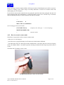
6.1.2
Surface Interface front panel description
The front panel with all switches and led indicators is described below:
Surface Interface Front Panel
The unit is powered by plugging the DC input supply, which immediately feeds the USB interfaces
and ROV RS485/RS232 interfaces. The other functions can be activated using the front panel
switches. All functions are clearly separated; switches and indicators are grouped by functions in
separate coloured areas.
It is preferable to avoid applying the DC supply when the unit is not in use.
6.1.2.1 Video overlay activation
To activate the video overlay, just switch it on, then the "ON" indicator will be active (red led).
The RX/TX indicators report the internal serial COM port signals states and may be used to check
dialog.
The "In" indicator (green led) is active when there is not video signal at the video input. If a video
signal is applied at the video input, the "In" indicator will be off.
The video overlay is drive by the AQUA-CAD software and does not require any other user attention.
When use of AQUA-CAD is not expected, user can drive the video overlay module by sending
appropriate commands through the serial link. The video overlay module included in the Surface
Interface is a BOB3 unit from Decade Engineering USA (www.decadenet.com) with firmware version
3.3. The BOB3 user manual may be provided by PLSM (please contact PLSM support). The BOB3
support PAL or NTSC, please choose the version suited to your need when ordering the AQUAMETRE R300 configuration.
6.1.2.2 ROV interface activation
There is no switch to activate the ROV interface since it is directly powered when applying external
DC supply to the unit.
AQUA-METRE R300/R3000 User Manual
Doc. N° 0112-801-011
Page 44 /95
www.plsm.eu
The RX/TX indicators report the internal serial COM port signals states and may be used to check
dialog.
6.1.2.3 Radio-modem activation
Before any radio-modem activation, make sure that the antenna is connected on the rear panel through
the coaxial cable (direct connection of the antenna on the rear panel may induced RF power on the
USB cable that may lead to USB error).
To activate the radio-modem, just switch it on, then the "ON" indicator will be active (red led).
The RX/TX indicators report the internal serial COM port signals states and may be used to check
dialog.
The "In range" is always activated (because the AEROCOMM module included is set as server).
To check the radio-modem, use the surface buoy connected to the Base (refer to chapter dedicated to
Surface Buoy).
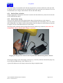
6.1.2.4 Direct Cable link activation
The direct cable link function can be used when short distance between the host PC and CM unit is
expected (typically less than 100 metres). In this case, a cable fitted with two MCIL-8-MP IMPULSE
connectors can be used to connect the CM unit (Base or Pointer) to the Surface interface. The CM can
then be powered by the Surface interface (recommended), but also just switched ON using the internal
batteries.
Surface
Interface
CM Unit
(Base or
Pointer)
USB
Cable with two
MCIL-8-MP male
connector from
IMPULSE
Configuration when using a direct cable link
To power the CM unit, just switch the "Vext" switch on (Vext like external Voltage), this will then
start the CM unit and activates the "Vext" indicator.
User may also use the ON/OFF switch that switch the CM unit using the internal batteries,, this will
then start the CM unit and activates the "On/Off" indicator.
The CM unit will consume batteries energy as long as the ON/OFF switch is on.
Do not switch both switches on simultaneously, it will not damage the unit but the CM will still on
even if external supply is removed (and continue to work on batteries).
The RX/TX indicators report the internal serial COM port signals states and may be used to check
dialog.
AQUA-METRE R300/R3000 User Manual
Doc. N° 0112-801-011
Page 45 /95
www.plsm.eu
6.2 Surface radio-modem buoy description
The surface radio-modem buoy is intended where distance from host PC and CM unit may not be set
up using a direct cable, this may be due to excessive distance (typically greater than 100 metres) or by
difficult site configuration. In this case a radio modem link may be set up between a surface buoy
(itself connect to the CM through an underwater cable) and the Surface Interface previously
described.
5 metres
coaxial cable
Surface
Interface
Radio-modem
Buoy
USB
F
M
F
Configuration
Cable
M
10 to 200m
Underwater Cable
R300 Base Unit
M
Configuration when using a radio-modem link
The distance between the surface buoy and the Surface interface antenna may be as far as 3 km
providing that direct line of sight is provided, at least 500 metres in case of masked path. The radiomodem is a licence free UHF type: 868 MHz for European applications, 915 MHz type for USA,
Canada and Australia. The output power is limited to 500 mW peak.
Refer to the Surface buoy labelling for the precise characteristics and approval ID.
AQUA-METRE R300/R3000 User Manual
Doc. N° 0112-801-011
Page 46 /95
www.plsm.eu
The surface buoy detailed description appears below:
UHF antenna
Flotation foam
Batteries pack
U/W Connector
Attache rop
The battery pack is sealed and cannot be changed by user; contact PLSM for a battery pack renewal.
The flotation foam is a low-density polyethylene type, it is not intended for a permanent water/sun
exposure. The U/W connector is a MCIL-8-FS connector from IMPULSE, it is recommended to
lubricate it using silicon oil (spray from 3M or equivalent), do not use silicon grease.
The surface radio-modem buoy must be connected to a small Male-Female configuration cable:
Configuration
Cable
Radio-Modem Buoy Configuration cable
This small cable is intended to switch on the Radio-Modem and select the mode of operation (wake
up by radio for instance).
AQUA-METRE R300/R3000 User Manual
Doc. N° 0112-801-011
Page 47 /95
www.plsm.eu
The Surface Buoy can be linked to the CM unit using the basic 10 metres underwater cable provided
by PLSM at delivery. PLSM can also provide Male-Female cable extension up to 100 metres (it is not
recommended to use a longer cable between CM unit and Surface Buoy).
6.2.1
Surface Buoy activation
Simply plugging the Configuration cable male connector into the female buoy connector activates the
surface Radio-Modem Buoy.
6.2.2
Surface Buoy charge
Always use the charger delivered with the Surface Buoy (P/N 0108-500-xxx), this charger is
especially designed to charge the NiMh batteries pack included in the Surface Buoy (10 x 1.2V, 9500
mA.h NiMh cells). The charger switches automatically from fast charge to trickle charge by detection
of negative dV/dT or maximum timeout for a total safety.
The charger male connector must be plugged first into the female buoy connector (do not leave the
configuration cable, it will not allow charger to operate!):
Plugging the charger male connector into the female Radio-Modem Buoy female connector
Then plug the charger in the main supply (100-240 VAC, 50/63Hz), different international plugs may
be provided by PLSM (Europe, US/CANADA, UK,…).
A green LED indicator on the charger indicates the charge completion status.
AQUA-METRE R300/R3000 User Manual
Doc. N° 0112-801-011
Page 48 /95
www.plsm.eu
7 MiniPointer for AQUA-METRE R300
This Pointer has been designed to address a large range of applications, including light survey ROV
like those used during dam survey. Moreover, the MiniPointer includes an accurate pressure gauge
that is used to counter thermocline effects on vertical coordinate when using the AQUA-METRE in
fresh water (lake, river,…).
The MiniPointer, like other R300 units, may be powered externally or using the internal batteries. An
RS232 serial link is also implemented, this link is optional during work but may be useful to monitor
the Pointer status and to securely report navigation message of the ROV including local static
pressure and ROV heading (using the internal electronic compass included in the MiniPointer). This
navigation message is send through the serial link each time the MiniPointer is interrogated by a Base
and the AQUA-CAD software process it in order to compensate ROV mounting offsets and display
ROV oriented in CAD software.
MiniPointer installed on a light survey class ROV
AQUA-METRE R300/R3000 User Manual
Doc. N° 0112-801-011
Page 49 /95
www.plsm.eu
7.1 MiniPointer electrical interfaces
The MiniPointer has two electrical bulkhead connector, one located on the top is the hydrophone(s)
connector, the other, located on the bottom of the unit, is the Interface & Power Supply connector:
Hydrophone(s)
Connector
Diam. 68mm
Diam. 60mm
175mm
Interface &
Power
Connector
Mini-Pointeur R300 (hydrophone not plugged)
Do never lubricate the connector with silicon or over type of grease,
always use a silicon oil instead
7.1.1
Hydrophone(s) Connector
Type: MCBH6-FS bulkhead from IMPULSE
Top Hydrophone(s) Connector
AQUA-METRE R300/R3000 User Manual
Doc. N° 0112-801-011
Page 50 /95
www.plsm.eu
Hydrophone(s) Connector Pinout:
Pin n°
Function
Pin n°
Function
1
HYD1-
5
HYD2-
2
HYD1+
6
HYD2+
3
Screen
7
Screen
Hydrophone installation:
To install the top hydrophone:
- plug the hydrophone connector and gently screw the locking sleeve,
- then screw the mini-mast on the top of the MiniPointer,
Hydrophone and Mini-mast installation
AQUA-METRE R300/R3000 User Manual
Doc. N° 0112-801-011
Page 51 /95
www.plsm.eu
7.1.2
Interface & Power Connector
Type: MCBH8-FS bulkhead from IMPULSE
Bottom Interface & Power Supply Connector
Interface & Power Connector Pinout:
Pin n°
Function
Pin n°
Function
1
GND_RS
5
GND
2
RX_RS
6
ON/OFF
3
TX_RS
7
GPI
4
EXT_SUPPLY
8
GPO
RX_RS, TX_RS : RS232 RX/TX signals (opto-isolated internally).
Nota : RX_RS is the Pointer input (downlink), TX_RS is the Pointer output (uplink).
AQUA-METRE R300/R3000 User Manual
Doc. N° 0112-801-011
Page 52 /95
www.plsm.eu
GND_RS: return path for RX_RS and TX_RS signals,
EXT_SUPPLY, GND: external power supply input:
- voltage must be between 12 and 34 Volts (24 Volts nominal),
- Curent maximum: 300mA @ 12V (typically : 100mA @ 24V)
When the external power supply is applied, it switches the MiniPointer on (no need to use
ON/OFF pin in this case).
ON/OFF: a short circuit between ON/OFF and GND pins switches the MiniPointer on using internal
batteries (PLSM offers ON/OFF plug for the MiniPointer),
DO NOT short ON/OFF and GND when you want to supply the MiniPointer using an external
power supply (it will put it in charge mode!)
GPI: opto-isolated general purpose digital input (0-5V maxi), the state of this input may be read and
transmitted by acoustic. Return path is the GND_RS pin.
GPO: sortie numérique 0-5V opto-couplées (l’état de cette sortie 0 ou 1 peut être lue et/ou modifiée
par commande acoustique). Le signal de retour est GND_RS (broche 1).
Recommended Connector for the Interface & Power :
Type: MCIL8-MP from IMPULSE
MCIL8-MP Connector (locking sleeve not shown)
AQUA-METRE R300/R3000 User Manual
Doc. N° 0112-801-011
Page 53 /95
www.plsm.eu
7.2 MiniPointer mechanical characteristics
AQUA-METRE R300/R3000 User Manual
Doc. N° 0112-801-011
Page 54 /95
www.plsm.eu
7.3 MiniPointer Installation on ROV
When installed on a ROV, two main constraints must be kept in mind:
- make sure the MiniPointer hydrophone will always be in line of sight from the Base. If masked by
the ROV flotation, the MiniPointer will not operate or may lead to erroneous measurements.
- in order to use the internal compass, the MiniPointer must be installed vertically (MiniPointer Z axis
being vertical) with the MiniPointer X axis oriented to the forward ROV direction (see Chapter 7.2
for an explanation of Z and X MiniPointer axis).
7.4 MiniPointer Charge
In active mode, the MiniPointer autonomy is around 14 hours (more than a full working day). Then,
when operated on batteries, it is recommended to charge the batteries at the end of the working day.
The charger is made of two parts: the charger interface (a), and the AC-DC adaptor (b).
Charge
interface
AC-DC
Adaptor
To charge the batteries of the MiniPointer:
- make sure the AC-DC adaptor is not powered (not plugged in the wall plug),
- plug the charge interface MCIL8-MP type of connector in the bottom bulkhead connector of the
MiniPointer,
- if not already done, plug the DC connector in the charge interface,
AQUA-METRE R300/R3000 User Manual
Doc. N° 0112-801-011
Page 55 /95
www.plsm.eu
- then power the AC-DC adaptor and check that the green LED is activated after 1 or 2 seconds,
- wait about 15 seconds, then the yellow LED will flash few times indicating the charge is in progress,
Charge Status:
During the batteries charge, the yellow LED flashes every 30 seconds indicating the charge process
status:
1 short flashs:
Charge in progress, about 10%
2 short flashs:
Charge in progress, about 20%
3 short flashs:
Charge in progress, about 40%
4 short flashs:
Charge in progress, about 60%
5 short flashs:
Charge in progress, about 80%
6 short flashs:
Charge completed
When completed, the charger process switches to steady charge, then no risk for the batteries when
you leave the charger activated for a long time.
AQUA-METRE R300/R3000 User Manual
Doc. N° 0112-801-011
Page 56 /95
www.plsm.eu
7.5 ROV Pointer serial link protocol & commands
7.5.1
Interface description
The interface is a RS232 serial communication line with 3 wires (TX, RX and Ground) with the
following characteristics:
Baud rate: 9600 Baud
Data length: 8 bits
Parity: none
Start bit: 1 (value 1)
Stop bit: 1 (value 0)
This serial port is internally opto-coupled to ensure proper isolation (ground loop)
Handshaking: every character send to the ROV Pointer unit will be echoed, no other protocol are
expected due to the low average data rate (less than 50 bytes per second, modern PC have large serial
COM buffer, typically 1024 bytes, allowing several seconds without missing message).
It is then possible to control the ROV Pointer using a simple terminal emulator (terminal.exe or
hyperterminal.exe of windows package). This feature is especially useful when checking and/or
servicing the units.
7.5.2
Monitor commands description
7.5.2.1 Monitor mode
When switched on, the ROV Pointer performs initialisation and, if no error encountered, bips two
times. If powered by internal batteries, it enters directly in sleeping mode waiting for wake up from
the acoustic or RS232 link (if connected). If powered by an external supply, it will just enters the
monitor modes.
IMPORTANT FEATURE:
During first initialisation, the ROV Pointer measures the static pressure and assumes that it is
the static pressure at the surface. All navigation messages reported including the current static
pressure are referenced to this initialisation pressure. Then, switching on the ROV Pointer
underwater will lead to an erroneous reference pressure, then erroneous current static
pressure. Other “INIT” command will initialise the Pointer again but not the reference pressure
again.
This was implemented to counter atmospheric pressure variation when working in high altitude lake.
Hereafter are described the Monitor commands that are specific to the ROV Pointer. For other
commands, please refer to the chapter 8 describing monitor commands of R300 units.
7.5.2.2 List of specific ROV Pointer Monitor Commands
The monitor commands list appears in the next table and are detailed below.
Command
Description
MODREP
Command to force Pointer acoustic answer
MODROV
Command to allow navigation message to be reported by acoustic
AQUA-METRE R300/R3000 User Manual
Doc. N° 0112-801-011
Page 57 /95
www.plsm.eu
7.5.2.2.1
MODREP command
This command activates or deactivates the forced reply mode:
MODREP 0
MODREP 1
(blank between MODREP and 0, to deactivate the mode)
(blank between MODREP and 1, to activate the mode)
This setting is saved in non-volatile memory then used until next setting.
When forced, reply mode is active; the Pointer will always interpret incoming acoustic messages as an
interrogation to him and then reply and report an interrogation.
Before activation of this mode, make sure that there is only one Pointer and a Base working on the
site (this is often the case during dam survey for instance). An excessive noise level may also generate
a lot of reply messages that may lead to erroneous positioning.
This mode is very useful when working in highly reverberant conditions, do not hesitate to contact
PLSM for advice when using this mode.
Reply delay and MODREP:
From embedded software 3.06 and later, the Pointer is able to operate in dual capture mode (see
DCAPT and DCAPI commands in chapter describing Base R300 commands). Thus, address setting
range is 1 to 31 instead of 1 to 15. When in forced reply mode (MODREP 1), a Pointer with address
from #01 to #15 reply with normal delay, and a Pointer with address from #16 to #31 reply with
additional delay of about 250 ms. It is then possible to work with forced reply mode and two Pointers
in dual capture mode.
7.5.2.2.2
MODROV command
This command activates or deactivates the reporting of navigation message through acoustic.
MODROV 0
MODROV 1
(blank between MODROV and 0, to deactivate the mode)
(blank between MODROV and 1, to activate the mode)
This setting is saved in non-volatile memory then used until next setting.
When active, the Pointer will send a navigation message through the acoustic each time it is
interrogated. This is a way to get these navigation data without any electrical link with the Pointer.
The message is received and reported by the CM unit. The navigation message is a quite long message
then not easy to transmit in highly reverberant conditions, it is why it is recommended to use a serial
link to report navigation data from the ROV Pointer.
The navigation message is reported by the CM as follow (also described in chapter 8).
DAT: ROVNAV (xx) HEAD= yyy.yy PRE= zz.zzz
Where:
- xx is the address of the Pointer,
- yyy.yy is the ROV Pointer heading from 000.00 to 359.99°
- zz.zzz is the static pressure measured in bars,
For instance:
DAT: ROVNAV (06) HEAD= 158.23 PRE= 12.758
Please refer to appendix to find how to transform pressure in bars to water depth.
AQUA-METRE R300/R3000 User Manual
Doc. N° 0112-801-011
Page 58 /95
www.plsm.eu
8 CM serial interface protocol (R300/R3000)
This chapter describes the protocol associated with Communication Master unit (CM), providing that
CM unit is a R300 Base (P/N: 0112-100-000), a R3000 Base (P/N: 0114-100-000), R3000 Pointer
(P/N: 0114-200-000) or R300 Pointer (P/N: 0112-200-000), it also describes the specific ROV
Pointer serial communication protocol described in a previous chapter (the commands specific to the
ROV Pointer are described in the chapter dedicated to it).
8.1 Interface description (serial port 0)
The interface is a regular RS232 serial communication line with 3 wires (TX, RX and Ground) with
the following characteristics:
Baud rate: 9600 Baud
Data length: 8 bits
Parity: none
Start bit: 1 (value 1)
Stop bit: 1 (value 0)
This serial port is internally opto-coupled to ensure proper isolation (ground loop)
Handshaking: every character send to the CM unit will be echoed, no other protocol are expected due
to the low average data rate (less than 50 bytes per second, modern PC have large serial COM buffer,
typically 1024 bytes, allowing several seconds without missing message).
It is then possible to control every unit (Base or Pointer) using a simple terminal emulator
(terminal.exe or hyperterminal.exe of windows package). This feature is especially useful when
checking and/or servicing the units. A basic interface tool may be provided by PLSM to allow
connection to a surface PC equipped with a serial RS232 COM port, this tool supply the unit with a
DC-DC converter plugged to main VAC (100 to 240 VAC/47 to 63 Hz).
8.2 Monitor commands description
8.2.1
Monitor mode
When switched on, a unit (Base or Pointer, not ROV Pointer) enters in sleeping mode (after a self test
sequence however). In this mode, the unit wait for external incoming command through acoustic or
serial link. To wake up the CM unit, just type “?” (question mark) until sleeping mode exit. This is
possible during a time window of about 2 seconds every 30 secondes. Thus me maximum time to unit
wake up is 30 secondes.
If user switches the unit with the terminal already connected, it is possible to jump directly to monitor
mode without entering sleeping mode. A message is displayed when the unit is switch on and allows
user do it for 4 seconds.
Hereafter are described the Monitor commands send from surface through serial link. Incoming
command from acoustic link are not described here because not directly accessible to user.
The CM unit also reports all incoming acoustic messages on the serial link. All report messages are
described hereafter.
AQUA-METRE R300/R3000 User Manual
Doc. N° 0112-801-011
Page 59 /95
www.plsm.eu
8.2.2
List of Monitor Commands
The monitor commands list appear in the next table and are detailed along the next chapters.
Command
Description
INIT jj
Initialisation (test and full calibration)of unit #jj
3.0
PING jj
Test the presence and/or wake up of unit #jj
3.0
CAPT jj nn
Capture of Pointer #jj using Base #nn without inclination compensation
3.0
CAPI jj nn
Capture of Pointer #jj using Base #nn with inclination compensation
3.05
INCL jj
Get the inclination angles (X and Y axis angle from horizontal) of unit #jj
3.0
HEAD jj
Heading (magnetic north) measurement of unit #jj
3.0
VBAT jj
Get the batteries voltage of unit #jj
3.0
VEMI jj
Get emitter voltage of unit #jj
3.0
TEMP jj
Get the internal temperature of unit #jj
3.0
REQC0 jj
Get the sound celerity taken into account by unit #jj
3.0
REQRT jj
Get the receiver threshold taken into account by unit #jj
3.0
REQMT jj
Get the noise level of each receiver way of unit #jj
3.0
PARAM jj
Get the parameters Heading and C0 of unit #jj
3.0
SETC0 jj
Force the sound celerity to be taken into account by unit #jj
3.0
SLEEP jj
Force the unit #jj in sleeping mode
3.0
SETRT jj
Force the receiver threshold to be taken into account by unit #jj
3.0
SETVE jj
Force the emitter voltage of unit #jj
3.0
DCAPT jj nn
Dual Capture of Pointer #jj and #(jj+16) modulo 32, using Base #nn
without inclination compensation
3.06
DCAPI jj nn
Dual Capture of Pointer #jj and #(jj+16) modulo 32, using Base #nn
with inclination compensation (for both Pointers)
3.06
SETMOD jj
Force the mode of operation of unit #jj
3.06
REQMOD jj
Get the mode of operation of unit #jj
3.06
AQUA-METRE R300/R3000 User Manual
Doc. N° 0112-801-011
from.
soft
version
Page 60 /95
www.plsm.eu
8.2.2.1 INIT jj command
This command activates self-tests and calibration of unit #jj (between 1 and 31). If the unit is a Base,
it also activates sound celerity measurement. In case of Pointer, default celerity of 1500 m/s is set
(Pointer does normally not use the celerity, but it is expected to be used for future features like
distance measurement by Pointer).
During the tests and calibration, the unit #jj sends the following report messages:
V_EMI message which gives emitter voltage actual setting,
THRESHOLD message indicating actual receiver threshold setting,
HEADING message for unit heading,
C0 message indicate the sound celerity setting for the unit,
V_BAT which gives batteries voltage,
STATUS message indicates unit reference number and warning or error status.
example:
INIT 10
(typed by user)
DAT: V_EMI (10)= 07.79
(returned by unit #10)
DAT: THRESHOLD (10)= 1.00
(returned by unit #10)
DAT: HEADING (10)= 265.80
(returned by unit #10)
DAT: C0 (10)= 1500.00
(returned by unit #10)
DAT: V_BAT (10)= 07.57
(returned by unit #10)
DAT: DISPO (10)= 0x20 WARNING= 0x000000
(returned by unit #10)
*
Refer to chapter describing report message for detail of content.
8.2.2.2 PING jj command
The PING command of unit #jj (jj between 1 and 31) forces the unit #jj to send the status message. It
also wake up the unit #jj if it was sleeping and was trying to wake up (for two seconds every 30
seconds). Then, if user want to wake up a specific unit, this message has to be send every 2 seconds
until unit wake up.
example:
PING 10
(typed by user)
DAT: DISPO (10)= 0x20 WARNING= 0x000000
(returned by unit #10)
*
Refer to chapter describing report message for detail of content.
8.2.2.3 CAPT jj nn command
This command forces the capture of unit #jj (jj between 1 and 31, Pointer or Base working in Pointer
mode) using the unit #nn (nn between 1 and 31, must be a Base). The capture process includes:
interrogation of unit #jj by unit #nn (providing that unit #nn is a Base), computation of angles and
distance by unit #nn, and emission of coordinate message from the unit #nn.
The interrogation message is reported by the CM (except if the Base which interrogates is also the
CM) and if capture successful, the coordinate message also. In case of capture failure, a capture error
message is reported.
Example when capture successful:
CAPT 10
(typed by user)
INTERR: PNT (15)
(returned by unit #10)
AQUA-METRE R300/R3000 User Manual
Doc. N° 0112-801-011
Page 61 /95
www.plsm.eu
COORD: PNT (15) AZ= 105.32, EL= 90.87, DIST= 167.564 (returned by unit #10)
*
Example when capture not successful:
CAPT 15 10
(typed by user)
MSG: BASE (10) CAPT. NO ANSWER
(returned by unit #10)
*
This last message occurs when Pointer do not answer
Example when unit #nn is not a Base, then not able to initiate a capture:
CAPT 15 10
(typed by user)
CM: CM UNIT (10) NOT ABLE TO CAPTURE
(returned by unit #10)
*
Refer to chapter describing report message for detail of content.
8.2.2.4 CAPI jj nn command
This command forces the capture of unit #jj (jj between 1 and 31, Pointer or Base working in Pointer
mode) using the unit #nn (nn between 1 and 31, must be a Base), the Base inclination is compensated
in order to give Z coordinates along zenith axis. The capture process includes: interrogation of unit #jj
by unit #nn (providing that unit #nn is a Base), computation of angles and distance by unit #nn (with
inclination measurement and compensation accordingly), and emission of coordinate message from
the unit #nn.
The inclination can be compensated if and only if the absolute inclination angle is less than 15.0°
from vertical. If the inclination is greater than 15.0°, an error message will be reported. When using
compensated capture, make sure that the mode of the Base is properly set (see MODB command later
in this chapter, or SETMOD and REQMOD commands if you are using units with embedded software
version 3.06 and later).
The interrogation message is reported by the CM (except if the Base which interrogates is also the
CM) and if capture successful, the coordinate message also. In case of capture failure, a capture error
message is reported.
Example when capture successful:
CAPI 15 10
(typed by user)
INTERR: PNT (15)
(returned by unit #10)
COORD: PNT (15) AZ= 105.32, EL= 90.87, DIST= 167.564 (returned by unit #10)
This message is reported by CM when the tilt angle is out of range.
MSG: UNIT (10) TILT>15°
(send by unit #10, the Base, when over-inclinated)
Example when capture not successful:
AQUA-METRE R300/R3000 User Manual
Doc. N° 0112-801-011
Page 62 /95
www.plsm.eu
CAPT 15 10
(typed by user)
MSG: BASE (10) CAPT. NO ANSWER
(returned by unit #10)
This message occurs when Pointer does not answer
Example when unit #nn is not a Base, then not able to initiate a capture:
CAPT 15 10
(typed by user)
CM: CM UNIT (10) NOT ABLE TO CAPTURE
(returned by unit #10)
*
Refer to chapter describing report message for detail of content.
8.2.2.5 INCL jj command
This command allows measurement of two axis inclination of the unit #jj (jj between 1 and 31). The
inclination report message is send back by the unit #jj.
Example:
INCL 10
(typed by user)
DAT: INCLIN. (10) X= +09.45 Y= -12.01
(returned by unit #10)
Where:
X is the angle between the X axis of the unit and the horizontal plane, and Y the angle between the Y
axis of the unit and the horizontal plane. The angles are positive when the axis goes below the
horizontal plane (see illustration below).
Z
Z’
X’
Y
αx
X
αy
Y’
In blue: local geographic coordinate system (with Y
axis North oriented and Z axis vertical)
In red: underwater unit coordinate system
Inclination angles definition, here αx is negative and αy positive
Note: these angles are not mathematically equivalent to the definition of pitch and roll angles.
AQUA-METRE R300/R3000 User Manual
Doc. N° 0112-801-011
Page 63 /95
www.plsm.eu
8.2.2.6 HEAD jj command
This command allows measurement of magnetic north heading of the unit #jj (jj between 1 and 31).
The heading is measured from the X” axis that is defined as the axis X’ after the single rotation (angle
αz) in the space that makes the Z’ axis being vertical (Z’’ and Z are identical after this rotation).
Z Z’’ Z’
αz
X’
Y
X’’
Y’’
X
HEADING
Y’
In blue: local geographic coordinate system (with Y
axis North oriented and Z axis vertical)
In red: underwater unit coordinate system
HEADING definition
A heading report message is send back by unit jj.
Example:
HEAD 10
(typed by user)
DAT: HEADING (10)= 096.67
(returned by unit #10)
*
Where:
The heading is an angle between 000.00 and 359.99 degrees (always positive).
Refer to chapter describing report message for detail of content.
8.2.2.7 VBAT jj command
This command allows reading of the batteries voltage of the unit #jj (jj between 1 and 31). A batteries
voltage report message is send back by unit jj.
Example:
VBAT 10
(typed by user)
DAT: V_BAT (10)= 08.15
(returned by unit #10)
AQUA-METRE R300/R3000 User Manual
Doc. N° 0112-801-011
Page 64 /95
www.plsm.eu
*
Where:
The batteries voltage in Volts, always positive, between 00.0 and 12.00.
Refer to chapter describing report message for detail of content.
8.2.2.8 VEMI jj command
This command allows reading of the emitter voltage of the unit #jj (jj between 1 and 31). An emitter
voltage report message is send back by unit jj.
Example:
VEMI 10
(typed by user)
DAT: V_EMI (10)= 07.50
(returned by unit #10)
*
Where:
The emitter voltage in Volts, always positive, between 00.0 and 12.00.
Refer to chapter describing report message for detail of content.
8.2.2.9 TEMP jj command
This command allows reading of the internal temperature of the unit #jj (jj between 1 and 31). A
temperature report message is send back by unit jj.
Example:
TEMP 10
(typed by user)
DAT: TEMP (10)= +24.7
(returned by unit #10)
*
Where:
The temperature is given in degrees Celsius between –35 and +90.
8.2.2.10 REQC0 jj command
This command allows reading of celerity taken into account by unit #jj (jj between 1 and 31). A
celerity report message is send back by unit jj.
Example:
REQC0 10
(typed by user)
DAT: C0 (10)= 1498.54
(returned by unit #10)
*
Where:
The sound celerity in metre per second is always positive, between 1200 and 1800.
Refer to chapter describing report message for detail of content.
8.2.2.11 REQRT jj command
This command allows reading of Receiver Threshold (RT) taken into account by unit #jj (jj between 1
and 31). A Receiver Threshold report message is send back by unit jj.
Example:
REQRT 10
AQUA-METRE R300/R3000 User Manual
Doc. N° 0112-801-011
(typed by user)
Page 65 /95
www.plsm.eu
DAT: THRESHOLD (10)= 1.00
(returned by unit #10)
*
Where:
The receiver threshold in Volts is always positive, between 0.5 and 1.8.
Refer to chapter describing report message for detail of content.
8.2.2.12 REQMT jj command
This command allows reading of receiver Measured Threshold (MT) of unit #jj (jj between 1 and 31).
A receiver Measured Threshold report message is send back by unit jj.
Example:
REQMT 10
(typed by user)
DAT: MEAS. THRESHOLD (10) V1-4= 0.51 0.47 0.55 0.51 (returned by unit #10)
*
Where:
The receiver measured threshold in Volts is always positive, between 0.0 and 2.5.
Refer to chapter describing report message for detail of content.
8.2.2.13 PARAM jj command
This command allows reading of celerity taken into account by unit #jj as well as heading (jj between
1 and 31). A parameter report message is send back by unit jj.
Example:
PARAM 10
(typed by user)
PARAM: UNIT (10) C0= 1498.54 HEAD.= 274.8
(returned by unit #10)
*
Where:
The sound celerity in metre per second is always positive, between 1200 and 1800.
The heading is an angle between 000.00 and 359.99 degrees (always positive).
This command is equivalent to command REQ_C0 and HEAD but in a single command.
Refer to chapter describing report message for detail of content.
8.2.2.14 SETC0 jj command
This command allows setting of celerity taken into account by unit #jj (jj between 1 and 31). A
celerity report message is send back by unit jj.
Example:
SETC0 10 1545.87
DAT: C0 (10)= 1545.87
(typed by user)
(returned by unit #10)
*
Where:
The sound celerity in metre per second is always positive, between 1200 and 1800.
Refer to chapter describing report message for detail of content.
8.2.2.15 SLEEP jj command
This command forces the unit #jj in sleeping mode(jj between 1 and 31). A sleeping report message is
send back by unit jj.
AQUA-METRE R300/R3000 User Manual
Doc. N° 0112-801-011
Page 66 /95
www.plsm.eu
Example:
SLEEP 10
(typed by user)
MSG: UNIT (10) SLEEPING
(returned by unit #10)
*
8.2.2.16 SETRT jj command
This command sets the Receiver Threshold (RT) taken into account by unit #jj (jj between 1 and 31).
A Receiver Threshold report message is send back by unit jj.
Example:
SETRT 10 1.2
DAT: THRESHOLD (10)= 1.18
(typed by user)
(returned by unit #10)
*
Where:
The receiver threshold in Volts is always positive, between 0.5 and 1.8.
The returned value may differ from the setting because it is the actual measured value.
DO NOT SET THE RECEIVER THRESHOLD TO A TOO HIGH VALUE BECAUSE IT CAN
MAKE THE UNIT BECOMING DEAF! (refer to chapter describing system set up for proper
use of this command)
Refer to chapter describing report message for detail of content.
8.2.2.17 SETVE jj command
This command sets the emitter voltage of the unit #jj (jj between 1 and 31). An emitter voltage report
message is send back by unit jj.
Example:
SETVE 10 6.2
(typed by user)
DAT: V_EMI (10)= 06.10
(returned by unit #10)
*
Where:
The emitter voltage in Volts is always positive, between 00.0 and 12.00. The emitter voltage returned
may be different because it is the actual measured value after setting.
Refer to chapter describing report message for detail of content.
8.2.2.18 DCAPI jj nn command
This command forces the dual capture of unit #jj and #(jj+16)modulo32 (jj between 1 and 31, Pointer
or Base working in Pointer mode) using the Base unit #nn (nn between 1 and 31, must be a Base), the
Base inclination is compensated in order to give Z coordinates along zenith axis. The capture process
includes: interrogation of unit #jj and #(jj+16)modulo32 by unit #nn (providing that unit #nn is a
Base), computation of angles and distance by unit #nn (with inclination measurement and
compensation accordingly), and emission of coordinate messages from the unit #nn.
The inclination can be compensated if and only if the absolute inclination angle is less than 15.0°
from vertical. If the inclination is greater than 15.0°, an error message will be reported. When using
compensated capture, make sure that the mode of the Base is properly set (see SETMOD and
REQMOD commands later in this chapter).
AQUA-METRE R300/R3000 User Manual
Doc. N° 0112-801-011
Page 67 /95
www.plsm.eu
The interrogation message is reported by the CM (except if the Base which interrogates is also the
CM) and if capture successful, the coordinate message also. In case of capture failure, a capture error
message is reported separately for each interrogated unit.
Example when capture successful:
DCAPI 05 10
(typed by user)
COORD: PNT (21) AZ= 105.32, EL= 090.87, DIST= 167.564 (returned by unit #10)
COORD: PNT (05) AZ= 023.55, EL= 110.25, DIST= 138.578 (returned by unit #10)
The following message is reported by CM when the tilt angle is out of range.
(send by unit #10, the Base, when over inclinated)
MSG: UNIT (10) TILT>15°
Example when dual capture not fully successful:
DCAPI 05 10
(typed by user)
COORD: PNT (21) AZ= 105.32, EL= 090.87, DIST= 167.564 (returned by unit #10)
MSG: BASE (10) CAPT. NO ANSWER
(returned by unit #10)
This message occurs when Pointer #05 does not answer for instance
Example when unit #nn is not a Base, then not able to initiate a capture:
CAPT 15 10
(typed by user)
CM: CM UNIT (10) NOT ABLE TO CAPTURE
(returned by unit #10)
*
Refer to chapter describing report message for detail of content.
Details of dual capture versus addresses:
A dual capture does not consist of sending two times a simple interrogation message through acoustic.
Only one message is sent to address #jj, the unit #jj will receive the interrogation and process to
answer immediately, the unit #(jj+16)modulo32 also receives the interrogation but emits the reply
after an additional delay of about 250 ms compared to unit #jj. The Base processes both replies and
send the coordinates results of unit #(jj+16)modulo32 first immediately followed by coordinates of
unit #jj. Note that a simple interrogation to each unit remains possible however using CAPT and
CAPI commands.
DCAPI 05 10 command will perform a dual capture of addresses #05 and #21,
When DCAPI 21 10 command will perform a dual capture of addresses #21 and #05
((21+16)modulo32=05).
Important constrain:
Dual capture has been introduced in embedded software version 3.06 and later to
address ROV heading measurement without compass, which gives better accuracy
especially when working near steel structures. But for internal timing issues, Pointers
AQUA-METRE R300/R3000 User Manual
Doc. N° 0112-801-011
Page 68 /95
www.plsm.eu
distances difference must be less than 40 metres. A greater distance difference may lead
to erroneous coordinates.
8.2.2.19 DCAPT jj nn command
Same command as DCAPI but without internal compensation of the Base inclination, thus the
coordinates are output according interferometric frame.
Refer to previous DCAPI command description for details.
8.2.2.20 SETMOD jj nn command
This command sets the mode of operation of unit #jj (jj between 1 and 31). The mode is an 8 bits
integer (mode range 0-255), in embedded software version 3.06 only the bit 0 is used and define the
acoustic head up or down option. This setting is very important when using a Base and the "CAPI" or
“DCAPI” command, because in this case the inclination of the Base will be compensate to always
output a coordinate with X,Y axis in the local horizontal plane and Z vertical.
SETMOD #jj 0
define a unit #jj working up (typically the case when a Base is set up on the
sea bed at the top of a mast for instance).
SETMOD #jj 1
define a unit working reversed (typically the case when a Base is hanged
from a taut wire from the surface during dam survey for instance).
Example:
SETMOD 10 0
(typed by user, blank between SETMOD and address)
DAT: MODE (10)= 0
(returned by unit #10)
*
The setting is stored in flash memory and remains valid until next SETMOD command. User can get
actual mode using the REQMOD command (see later in this chapter).
8.2.2.21 REQMOD jj command
This command query the mode of operation of unit #jj (jj between 1 and 31). The mode is an 8 bits
integer (mode range 0-255), in embedded software version 3.06 only the bit 0 is used and define the
acoustic head up or down option. This setting is very important when using a Base and the "CAPI" or
“DCAPI” command, because in this case the inclination of the Base will be compensate to always
output a coordinate with X,Y axis in the local horizontal plane and Z vertical.
Example:
REQMOD 10
(typed by user, blank between REQMOD and address)
DAT: MODE (10)= 0
(returned by unit #10)
*
The setting is stored in flash memory and remains valid until next SETMOD command.
AQUA-METRE R300/R3000 User Manual
Doc. N° 0112-801-011
Page 69 /95
www.plsm.eu
8.2.3
List of CM command
These commands are dedicated to the CM unit only and then not addressed. They are mainly
dedicated to unit configuration setting and error reporting.
Command
Description
From.
embedded
software
version
ADDCHG jj
Set a new address #jj for the unit (CM only)
3.0
MODB j
Define the mode up or reversed (CM only)
3.0
DISPO
Get the CM unit identification (CM only)
3.0
LERR
Get the CM unit list of reported error and warning (CM only)
3.0
MODECHO j
Set the CM unit command echo mode to #j level (CM only)
3.06
8.2.3.1 ADDCHG command
This command sets the CM unit address between 1 and 31. A CM message is echoed.
Example:
ADDCHG 12
(typed by user)
NEW ADR= 12
(returned by unit CM)
*
This command is intended for system set up only. It is not recommended to use it during underwater
operation. It is not possible to set a new address through acoustic link (only the CM unit through the
serial electrical link).
MAKE SURE THAT THERE IS NETHER TWO UNITS WITH SAME ADDRESS, IT WILL
LEAD TO DEMODULATION MESSAGE ERROR AND IMPROPER WORK.
The current configuration may be checked using the DISPO command.
8.2.3.2 MODB command
This command has been replaced by SETMOD and REQMOD commands in embedded software
version 3.06 and later. These new commands allow setting of units through acoustics.
This command defines if the unit is working up or reversed, a confirmation message is echoed. This
setting remains in non volatile memory and define the working mode of the unit until the next setting.
This setting is very important when using a Base and the "CAPI" command, because in this case the
inclination of the Base will be compensate to always output a coordinate with X,Y axis in the local
horizontal plane and Z vertical.
MODB 0
define a unit working up (typically the case when a Base is set up on the sea bed at the
top of a mast for instance).
MODB 1
define a unit working reversed (typically the case when a Base is hanged from a taut
wire from the surface during dam survey for instance).
Example:
AQUA-METRE R300/R3000 User Manual
Doc. N° 0112-801-011
Page 70 /95
www.plsm.eu
MODB 0
(typed by user, blank between MODB and address)
Mode= 0
(returned by unit CM)
*
This command is intended for system set up only. It is not recommended to use it during underwater
operation. It is not possible to set the mode of another Base through acoustic link (only the CM unit
through the serial electrical link).
The current configuration may be checked using the DISPO command.
8.2.3.3 DISPO command
This command just return the full identification of the unit:
Example (in case of an AQUA-METRE R300 Base):
DISPO
(typed by user)
BASE AQUA-METRE R300 (DISPO= 17)
BASE AQUA-METRE R300 (DISPO= 17)
(returned by unit CM)
(device identification returned by unit CM)
Version Logiciel= 305
(embedded software release returned by unit CM)
Version Materiel= 203
(hardware version returned by unit CM)
Numero Serie= 101
(serial number returned by unit CM)
Mode= 0
(mode defined by previous MODB command returned by unit CM)
Adresse= 10
(current unit address returned by unit CM)
*
This command is information only and does not affect current setting.
8.2.3.4 LERR command
This command just return the list of reported error and warning:
Example:
LERR
(type by user)
NB M/A= 57
(returned by unit)
M/A= 00001 ERREUR=
0 ALERTE=
6008
(returned by unit)
M/A= 00002 ERREUR=
0 ALERTE=
6008
(returned by unit)
M/A= 00003 ERREUR=
0 ALERTE=
6008
(returned by unit)
M/A= 00004 ERREUR=
0 ALERTE=
6008
(returned by unit)
M/A= 00035 ERREUR=
0 ALERTE=
4008
(returned by unit)
This command is information only and does not affect current setting, It is detailed in the chapter
dedicated to BIT functions (Build In Tests).
AQUA-METRE R300/R3000 User Manual
Doc. N° 0112-801-011
Page 71 /95
www.plsm.eu
8.2.3.5 MODECHO command
This command sets the CM unit echo to commands mode.
The syntax is:
MODECHO j
(typed by user, blank between MODECHO and argument j)
Where j stands for the echo mode, j= 0, 1 or 2:
0: no echo of command,
1: echo to command after the carriage return character (the full command is then echoed in a single
stream),
2: full echo to every character send by user, this is the default mode when unit is switched on (the
setting is not stored in flash configuration memory).
exemple:
(typed by user, blank between MODECHO and 1)
MODECHO 1
MODE ECHO= 1 (SINGLE ECHO)
(returned by unit CM)
*
Note: the echo mode #1 (single echo) is recommended when operating the CM unit through a radiomodem link because it reduces the global time to send a command (the radio-modem do not have to
switch from receiver to emitter for each character echoed, the echo is sent in a single radio packet).
AQUA-METRE R300/R3000 User Manual
Doc. N° 0112-801-011
Page 72 /95
www.plsm.eu
8.2.4
List of Report messages
The report messages list appear in the next table and are detailed along the next chapters.
All messages that start with “REQ:” are request messages. These messages are usually send by the
CM to a remote unit and are often followed by the answer that is normally a data (DAT) message.
This request messages are not reported by the CM because they are send by it, but they can be
reported by a passive (listen only) secondary CM unit.
All messages that start with “DAT” are data messages. These messages carry information and are
generally send as an answer to request messages.
All messages that start with “SET” are setting messages. These messages set some parameters of
remote units. These messages are usually send by the CM to a remote unit and are often followed by
the answer that is normally a data (DAT) message. This request messages are not reported by the CM
because they are send by it, but they can be reported by a passive (listen only) secondary CM unit.
All messages that start with “MSG” are information messages. These messages carry state of the unit.
Message
Description
NOISE/DEMOD ERR
Demodulation error or incoming noise on CM receiver
INTERR: PNT (jj)
Reports an interrogation of unit #jj
REQ: CAPT PNT (jj) FROM BASE (nn) Reports a capture request of Pointer #jj using Base #nn
COORD: PNT (jj)...
Reports the coordinates measured of the Pointer jj
following an interrogation
REQ: PING (jj)
Reports a request of status of unit #jj
REQ: INCLIN. (jj)
Reports a request of inclination angles of unit #jj
REQ: HEADING (jj)
Reports a request of heading angle of unit #jj
REQ: PARAM. (jj)
Reports a request of parameter of unit #jj
REQ: C0 (jj)
Reports a request of celerity of unit #jj
REQ: THRESHOLD (jj)
Reports a request of receiver threshold of unit #jj
REQ: V_EMI (jj)
Reports a request of emitter voltage of unit #jj
REQ: V_BAT (jj)
Reports a request of batteries voltage of unit #jj
REQ: TEMP (jj)
Reports a request of internal temperature of unit #jj
REQ: REC. LEVEL (jj)
Reports a request of measured receiver level of unit #jj
REQ: INIT (jj)
Reports a request of initialisation of unit #jj
SET: C0 (jj)
Reports a celerity setting for unit #jj
SET: SLEEP (jj)
Reports a sleeping mode activation for unit #jj
SET: THRESHOLD (jj)
Reports a receiver threshold setting for unit #jj
SET: V_EMI (jj)
Reports a voltage emitter setting for unit #jj
AQUA-METRE R300/R3000 User Manual
Doc. N° 0112-801-011
Page 73 /95
www.plsm.eu
DAT: INCLIN. (jj)
Reports the inclination angles of unit #jj
DAT: HEADING (jj)
Reports the heading angle of unit #jj
DAT: C0 (jj)
Reports the celerity taken into account by unit #jj
DAT: DISPO (jj) & WARNING
Reports device code and warning status of unit #jj
DAT: DISPO (jj) & ERROR
Reports device code and error status of unit #jj
DAT: MEAS. THRESHOLD (jj)
Reports measured receiver level of unit #jj
DAT: THRESHOLD (jj)
Reports receiver threshold of unit #jj
DAT: V_EMI (jj)
Reports emitter voltage of unit #jj
DAT: V_BAT (jj)
Reports batteries voltage of unit #jj
DAT: TEMP (jj)
Reports internal temperature of unit #jj
DAT: ROVNAV (jj)
Reports navigation message of unit #jj (ROV Pointer)
DAT: MODE (jj)
Reports mode of operation of unit #jj
MSG: UNIT (jj) SLEEPING
Reports activation of sleeping mode for unit #jj
PARAM: UNIT (jj)…
Reports parameters of unit #jj
COORD: PNT (jj)…
Reports coordinates of unit #jj
8.2.4.1 NOISE/DEMOD ERR report message
This message is reported when a demodulation error occurred in the CM acoustic receiver. This may
be due to the reception of a real acoustic message in very reverberant environment, which leads to
demodulation error. It also may come from an incoming acoustic noise or induced electrical noise.
IMPORTANT:
When initialisation of an underwater Base unit occurs, it will induce the NOISE/DEMOD ERR
message when trying to measure local celerity, it is normal and last for about one minute or less.
A NOISE/DEMOD ERR message may also be displayed after an interrogation message due to unit
acoustic answer (short multi-frequencies pulse not interpreted as a message).
Except for the above reasons, if this message is displayed too often, try to increase the receiver
threshold.
example:
NOISE/DEMOD ERR
8.2.4.2 INTERR: PNT (jj)report message
This message is reported by CM when an interrogation is send to the unit #jj (jj between 1 and 31
included). It is also a confirmation that the Base that interrogates has received the capture request
message.
Example:
INTERR: PNT (10)
AQUA-METRE R300/R3000 User Manual
Doc. N° 0112-801-011
Page 74 /95
www.plsm.eu
8.2.4.3 COORD: PNT (jj) report message
This message is reported by the unit that performed the capture (interrogation of unit #jj, coordinates
computations and emission of coordinate message).
Example:
COORD: PNT (10) AZ= 182.32, EL= 95.37, DIST= 012.368
where:
EL
M
Z
DIST
Y
{0,0,0}
AZ
X
AZ is the azimuth angle in degrees of the unit #jj in the local coordinate system of the Base unit (refer
to interferometric frame geometry definition), 000.00≤ AZ ≤ 359.99,
EL is the elevation angle in degrees of the unit #jj in the local coordinate system of the Base unit
(refer to interferometric frame geometry definition), 000.00≤ EL ≤ 179.99,
EL is the distance in metres of the unit #jj in the local coordinate system of the Base unit (refer to
interferometric frame geometry definition), 000.000≤ DIST ≤ 262.140,
8.2.4.4 PARAM: UNIT (jj) report message
This message is reported by CM when a parameter message is send from the unit #jj (jj between 1 and
31 included).
Example:
PARAM: UNIT (10) C0= 1487.36 HEAD.= 279.6
where:
where C0 unity is metre per second (m/s), between 1200 and 1800 m/s. The heading is an angle
between 000.00 and 359.99 degrees (always positive).
(refer also to DAT: C0 and DAT: HEADING message for full explanation of content).
AQUA-METRE R300/R3000 User Manual
Doc. N° 0112-801-011
Page 75 /95
www.plsm.eu
REQUEST MESSAGES
8.2.4.5 REQ: CAPT PNT (jj) FROM BASE (nn) report message
This message is reported by CM when a capture request is send to the unit #nn (nn between 1 and 31
included). This message is in fact rarely reported because this is often the CM that sends this message
following the monitor command CAPT.
Example:
REQ: CAPT PNT (10) FROM BASE (15)
8.2.4.6 REQ: PING (jj) report message
This message is reported by CM when a PING request is send to the unit #jj (jj between 1 and 31
included). This message is in fact rarely reported because this is often the CM that sends this request.
Example:
REQ: PING (10)
8.2.4.7 REQ: INCLIN. (jj) report message
This message is reported by CM when an inclination angles request is send to the unit #jj (jj between
1 and 31 included). This message is in fact rarely reported because this is often the CM that sends this
request.
Example:
REQ: INCLIN. (10)
8.2.4.8 REQ: HEAD (jj) report message
This message is reported by CM when a heading angle request is send to the unit #jj (jj between 1 and
31 included). This message is in fact rarely reported because this is often the CM that sends this
request.
Example:
REQ: HEAD (10)
8.2.4.9 REQ: PARAM. (jj) report message
This message is reported by CM when a parameters request is send to the unit #jj (jj between 1 and 31
included). This message is in fact rarely reported because this is often the CM that sends this request.
Example:
REQ: PARAM. (10)
8.2.4.10 REQ: C0 (jj) report message
This message is reported by CM when a sound celerity request is send to the unit #jj (jj between 1 and
31 included). This message is in fact rarely reported because this is often the CM that sends this
request.
Example:
REQ: C0 (10)
AQUA-METRE R300/R3000 User Manual
Doc. N° 0112-801-011
Page 76 /95
www.plsm.eu
8.2.4.11 REQ: THRESHOLD (jj) report message
This message is reported by CM when a receiver threshold request is send to the unit #jj (jj between 1
and 31 included). This message is in fact rarely reported because this is often the CM that sends this
request.
Example:
REQ: THRESHOLD (10)
8.2.4.12 REQ: V_EMI (jj) report message
This message is reported by CM when a emitter voltage request is send to the unit #jj (jj between 1
and 31 included). This message is in fact rarely reported because this is often the CM that sends this
request.
Example:
REQ: V_EMI (10)
8.2.4.13 REQ: V_BAT (jj) report message
This message is reported by CM when a batteries voltage request is send to the unit #jj (jj between 1
and 31 included). This message is in fact rarely reported because this is often the CM that sends this
request.
Example:
REQ: V_BAT (10)
8.2.4.14 REQ: TEMP (jj) report message
This message is reported by CM when a internal temperature request is send to the unit #jj (jj between
1 and 31 included). This message is in fact rarely reported because this is often the CM that sends this
request.
Example:
REQ: TEMP (10)
8.2.4.15 REQ: REC. LEVEL (jj) report message
This message is reported by CM when a receiver level request is send to the unit #jj (jj between 1 and
31 included). This message is in fact rarely reported because this is often the CM that sends this
request.
Example:
REQ: REC. LEVEL (10)
8.2.4.16 REQ: INIT (jj) report message
This message is reported by CM when an initialisation request is send to the unit #jj (jj between 1 and
31 included). This message is in fact rarely reported because this is often the CM that sends this
request.
Example:
REQ: INIT (10)
AQUA-METRE R300/R3000 User Manual
Doc. N° 0112-801-011
Page 77 /95
www.plsm.eu
SETTING MESSAGES
8.2.4.17 SET: C0 (jj) report message
This message is reported by CM when a sound celerity setting is send to the unit #jj (jj between 1 and
31 included). This message is in fact rarely reported because this is often the CM that sends this
request.
Example:
SET: C0 (10) 1489.36
8.2.4.18 SET: SLEEP (jj) report message
This message is reported by CM when a sleeping mode activation setting is send to the unit #jj (jj
between 1 and 31 included). This message is in fact rarely reported because this is often the CM that
sends this request.
Example:
SET: SLEEP (10)
8.2.4.19 SET: THRESHOLD (jj) report message
This message is reported by CM when a receiver threshold setting is send to the unit #jj (jj between 1
and 31 included). This message is in fact rarely reported because this is often the CM that sends this
request.
Example:
SET: THRESHOLD (10) 1.23
8.2.4.20 SET: V_EMI (jj) report message
This message is reported by CM when an emitter voltage setting is send to the unit #jj (jj between 1
and 31 included). This message is in fact rarely reported because this is often the CM that sends this
request.
Example:
SET: V_EMI (10) 07.69
AQUA-METRE R300/R3000 User Manual
Doc. N° 0112-801-011
Page 78 /95
www.plsm.eu
DATA MESSAGES
8.2.4.21 DAT: INCLIN. (jj) report message
This message is reported by CM when an inclination angles data is send from the unit #jj (jj between
1 and 31 included). This message is often send after an inclination request.
Example:
DAT: INCLIN. (10) X= +09.45 Y= -12.01
(returned by unit #10)
Where:
X is the angle between the X axis of the unit and the horizontal plane, and Y the angle between the Y
axis of the unit and the horizontal plane. The angles are positive when the axis goes below the
horizontal plane (see illustration below).
Z
Z’
X’
Y
αx
X
αy
Y’
In blue: local geographic coordinate system (with Y
axis North oriented and Z axis vertical)
In red: underwater unit coordinate system
Inclination angles definition, here αx is negative and αy positive
Note: these angles are not mathematically equivalent to the definition of pitch and roll angles.
8.2.4.22 DAT: HEAD (jj) report message
This message is reported by CM when a heading angle data is send from the unit #jj (jj between 1 and
31 included). This message is often send after a heading request.
Example:
(returned by unit #10)
DAT: HEADING (10)= 096.67
Where:
The heading is an angle between 000.00 and 359.99 degrees (always positive).
AQUA-METRE R300/R3000 User Manual
Doc. N° 0112-801-011
Page 79 /95
www.plsm.eu
The heading is measured from the X” axis that is defined as the axis X’ after the single rotation (angle
αz) in the space that makes the Z’ axis being vertical (Z’’ and Z are identical after this rotation).
Z Z’’ Z’
αz
X’
Y
X’’
Y’’
X
HEADING
Y’
In blue: local geographic coordinate system (with Y
axis North oriented and Z axis vertical)
In red: underwater unit coordinate system
HEADING definition
8.2.4.23 DAT: C0 (jj) report message
This message is reported by CM when a sound celerity data is send from the unit #jj (jj between 1 and
31 included). This message is often send after a sound celerity request or setting (refer to REQC0 or
SETC0 monitor command).
Example:
DAT: C0 (10)= 1452.36
(returned by unit #10)
where C0 unity is metre per second (m/s), between 1200 and 1800 m/s.
8.2.4.24 DAT: DISPO (jj) & WARNING report message
This message is reported by CM when a warning status data is send from the unit #jj (jj between 1
and 31 included). This message is often send after PING to unit #jj.
Example:
DAT: DISPO (10)= 0x20 WARNING= 0x000000
(returned by unit #10)
where:
Dispo code is the device code (0x10 for D3000 Base and 0x20 for a D3000 Pointer) and warning code
includes all warnings set during the last initialisation (to be listed later).
Note: all warning codes are also stored in flash memory and can be read using the AQUA-TOOL or
AQUA-CAD software.
AQUA-METRE R300/R3000 User Manual
Doc. N° 0112-801-011
Page 80 /95
www.plsm.eu
8.2.4.25 DAT: DISPO (jj) & ERROR report message
This message is reported by CM when an error status data is send from the unit #jj (jj between 1 and
31 included). This message is often send after PING to unit #jj.
Example:
DAT: DISPO (10)= 0x20 ERROR= 0x000000
(returned by unit #10)
where:
Dispo code is the device code (0x10 for D3000 Base and 0x20 for a D3000 Pointer) and error code
includes all error set during the last initialisation (to be listed later).
Note: all error codes are also stored in flash memory and can be read using the AQUA-TOOL or
AQUA-CAD software.
8.2.4.26 DAT: MEAS. THRESHOLD (jj)… report message
This message is reported by CM when measured threshold data is send from the unit #jj (jj between 1
and 31 included). This message is often send after a request to unit #jj.
Example:
DAT: MEAS. THRESHOLD (10) V1-4=0.51 0.47 0.47 0.55
(returned by unit #10)
where:
The measured thresholds are the actual noise level for each receiver channel. This is a voltage
outputted from a logarithmic amplifier with 25 mV per dB. In case of Pointer, only channel #1 is
relevant (the other channel measured threshold will be 0.00). The tuned receiver threshold is 1.0 if
measured receiver threshold are less or equal to 1.0. A typical measured value is between 0.35 and
0.75, if greater than 1.0, the tuned receiver threshold will be set above 1.0 and the range will be
affected.
8.2.4.27 DAT: THRESHOLD (jj) report message
This message is reported by CM when a receiver threshold data is send from the unit #jj (jj between 1
and 31 included). This message is often send after a request or setting to unit #jj.
Example:
DAT: THRESHOLD (10)= 1.02
(returned by unit #10)
where:
The tuned receiver threshold is 1.0 if measured receiver threshold are less or equal to 1.0. A typical
measured value is between 0.35 and 0.75, if greater than 1.0, the tuned receiver threshold will be set
above 1.0 and the range will be affected.
8.2.4.28 DAT: V_EMI (jj) report message
This message is reported by CM when an emitter voltage data is send from the unit #jj (jj between 1
and 31 included). This message is often send after a request or setting to unit #jj.
Example:
DAT: V_EMI (10)= 08.52
(returned by unit #10)
where:
The emitter voltage can be tuned by user to lower the radiated power and improve behaviour in highly
reverberant environment. It is set to 8.5 volts during initialisation and may not be changed by user
when working in open area (may only be changed when working in harbour or closed to pier is
expected).
AQUA-METRE R300/R3000 User Manual
Doc. N° 0112-801-011
Page 81 /95
www.plsm.eu
8.2.4.29 DAT: V_BAT (jj) report message
This message is reported by CM when a batteries voltage data is send from the unit #jj (jj between 1
and 31 included). This message is often send after a request to unit #jj.
Example:
DAT: V_BAT (10)= 08.12
(returned by unit #10)
where:
The batteries voltage typical value is between 7.5 and 9.5 volts. A batteries voltage lower than 7.5 and
greater than 6.5 will issue a warning, and an error if lower than 6.5 Volts.
If the unit is powered by external supply, this voltage will be constant, about 9.3 Volts (+/-0.5),
providing that external supply voltage remains in the range 15 to 27 Volts.
8.2.4.30 DAT: TEMP (jj) report message
This message is reported by CM when an internal temperature data is send from the unit #jj (jj
between 1 and 31 included). This message is often send after a request to unit #jj.
Example:
DAT: TEMP (10)= +25.2
(returned by unit #10)
where:
The temperature unity is degree Celsius between –35 and +90 °C.
8.2.4.31 DAT: ROVNAV (jj) report message
This message is reported by CM when a ROV Pointer #jj has been interrogated and configured to
send navigation message through the acoustic after an interrogation (see chapter describing the ROV
Pointer for more details).
Only a R300/R3000 Base or Pointer with embedded software 3.04 or later can report this message.
The message is send according the format:
DAT: ROVNAV (xx) HEAD= yyy.yy PRE= zz.zzz
Where:
- xx is the address of the ROV Pointer,
- yyy.yy is the ROV Pointer heading from 000.00 to 359.99°
- zz.zzz is the static pressure measured in bars (Newton per cm2),
Example:
DAT: ROVNAV (06) HEAD= 158.23 PRE= 12.758
Please refer to appendix to find how to transform pressure in bars to water depth.
8.2.4.32 DAT: MODE (jj) report message
This message is reported by CM when a mode of operation data is send from the unit #jj (jj between 1
and 31 included). This message is send after a mode request or set to unit #jj.
Only a R300/R3000 Base or Pointer with embedded software 3.06 or later can report this message.
The message is send according the format:
DAT: MODE (jj) = yyy
Where:
- jj is the address of the unit,
AQUA-METRE R300/R3000 User Manual
Doc. N° 0112-801-011
Page 82 /95
www.plsm.eu
-
yyy is the mode of operation of unit #jj between 0 and 255 (see SETMOD command for
explanation of different modes of operation).
Example:
DAT: MODE (10)= 0
AQUA-METRE R300/R3000 User Manual
Doc. N° 0112-801-011
(returned by unit #10)
Page 83 /95
www.plsm.eu
MSG (info) MESSAGES
8.2.4.33 MSG: UNIT (jj) TILT>10° report message
This message is reported by CM when the tilt angle of the unit #jj (jj between 1 and 31 included) is
greater than 10°. This message is only send if compensated coordinate are expected.
Example:
MSG: UNIT (10) TILT>15°
(send by unit #10)
8.2.4.34 MSG: UNIT (jj) CAPT. NO ANSWER° report message
This message is reported by CM when the unit #jj (jj between 1 and 31 included) do not succeed in
getting any answer to interrogation. This message is only send if a capture request was send to this
unit.
Example:
MSG: UNIT (10) CAPT. NO ANSWER
(send by unit #10)
8.2.4.35 MSG: UNIT (jj) CAPT. CALC. ERROR report message
This message is reported by CM when the unit #jj (jj between 1 and 31 included) do not succeed in
computing coordinate solution following capture measurement. This message is only send if a capture
request was send to this unit.
Example:
MSG: UNIT (10) CAPT. CALC. ERROR
(send by unit #10)
8.2.4.36 MSG: UNIT (jj) CAPT. MULTIPATH ERROR report message
This message is reported by CM when the unit #jj (jj between 1 and 31 included) do not succeed in
computing coordinate solution due to multipath environment. This message is only send if a capture
request was send to this unit.
Example:
MSG: UNIT (10) CAPT. MULTIPATH ERROR
(send by unit #10)
8.2.4.37 MSG: UNIT (jj) SLEEPING report message
This message is reported by CM when the unit #jj (jj between 1 and 31 included) enters sleeping
mode. This message is only send if a sleeping mode request was send to this unit.
Example:
MSG: UNIT (10) SLEEPING
AQUA-METRE R300/R3000 User Manual
Doc. N° 0112-801-011
(send by unit #10)
Page 84 /95
www.plsm.eu
9 System maintenance, build in tests
9.1 System maintenance
9.1.1
Fresh water rinsing
After use in salted or polluted water, a complete rinsing must be achieved before drying. Drying
without prior rinsing would lead to salt deposit. Should it happen, dive the system in fresh water for at
least one hour. Flush the water and repeat until all salt traces are dissolved.
9.1.2
R300 Base/Pointer batteries charge
AQUA-METRE R300 (Base or Pointer) Charge plug
Plug the charger on the base/Pointer connectors located on the housing cap then plug the
charge adapter into the wall main AC supply (100 to 260VAC, 47 to 63 Hz). After about 30
seconds indicators will light to confirm that the batteries charge started.
Warning: The charge is automatic, provided that the battery charger is actually
plugged on, and that there is required electrical current. The On plug nor basic
interface should not be used during the battery charge.
Note: The battery charge adapter may be fitted with different plug adaptors to be used in
several countries. Europe, US, UK, Australia,... Please contact PLSM ([email protected] ) if you don’t have the right plug.
During the battery charge, the battery led twinkle about every 30 seconds indicating the
charge processing step:
1x red, 5x green:
Charge in progress, about 80%
2x red, 4x green:
Charge in progress, about 65%
3x red, 3x green:
Charge in progress, about 50%
4x red, 2x green:
Charge in progress, about 30%
5x red, 1x green:
Charge in progress, about 15%
6x green :
AQUA-METRE R300/R3000 User Manual
Doc. N° 0112-801-011
Charge completed (steady charge)
Page 85 /95
www.plsm.eu
6x red:
Charge error
When the charge is completed, the system automaticaly reduce the current to a steady
charge, thus it is recomended to unplug the battery charger (even if there is no risk of
batteies dammage). Then the base will shut down automatically.
In case of charge error (cycles of 6 red twinkling lights), unplug the battery charger and have
the base rest for at least two hours. Then try again the battery charge.
The battery charge error may come from over temperature (greater than 40°C), excessive
charge duration (more than 12 hours) or a too high batteries voltage.
DO NOT PLUG A CHARGER NOT DEDICATED TO THE AQUA-METRE R300,
THIS MAY DAMAGE THE UNIT.
Advanced users: it is possible to get batteries charge status using the infrared link and a PC
with a terminal emulator (like hyperterminal of Windows, 9600,N,1).
9.1.3
R3000 Base/Pointer batteries charge
The R3000 batteries charge scheme slightly differs from R300, the R3000 units do not have
specific plugs dedicated to this function, then the charge is made through the interface
connector using the internal DC-DC converter.
AC-DC
Converter
R3000
Charger
R3000 Pointer with AC-DC Converter and Charger
A specific charger is provided with each unit, to enter
charge mode, just follow the steps:
1) connect the charger to the unit (R3000 Base or
Pointer),
Step #1
Connect the
charger to the
R3000 unit
AQUA-METRE R300/R3000 User Manual
Doc. N° 0112-801-011
Page 86 /95
www.plsm.eu
2) connect the AC-DC converter to the wall
supply (100 to 260 VAC, 40 to 60Hz),
Step #2
Connect the ACDC Converter to
the wall supply
then and only then:
3) connect the DC plug (2.5mm
type, +24V in the centre) to the
charger.
Step #3
Connect the DC
plug to the
charger
A green led will light that indicate a proper DC
supply.
Check the green
led indicator
Nota: if you connect the DC plug before the wall supply, the AC-DC converter will not
be sufficient to supply surge current and the internal DC-DC converter of the unit will
not start. This may damage it !
AQUA-METRE R300/R3000 User Manual
Doc. N° 0112-801-011
Page 87 /95
www.plsm.eu
About 45 seconds after, the unit will emit acoustic beeps with the hydrophone (the
interferometric frame should be plugged to the Base unit) to confirm that the batteries
charge started.
Note: The battery charge adapter may be fitted with different plug adaptors to be used in
several countries. Europe, US, UK, Australia,... Please contact PLSM ([email protected] ) if you don’t have the right plug.
During the battery charge, the unit beeps about every 30 seconds indicating the charge
processing step:
5 short bips:
Charge in progress, about 80%
4 short bips:
Charge in progress, about 65%
3 short bips:
Charge in progress, about 30%
2 short bips:
Charge in progress, about 15%
1 short bips:
Pre-charge (in case of deep discharge)
1 long bips:
Charge error
When the charge is completed, the system automaticaly reduce the current to a steady
charge, thus it is recomended to unplug the battery charger (even if there is no risk of
batteies dammage). Then the base will shut down automatically.
In case of charge error, unplug the battery charger and have the unit rest for at least two
hours. Then try again the battery charge.
The battery charge error may come from over temperature (greater than 40°C), excessive
charge duration (more than 12 hours) or a too high batteries voltage.
DO NOT PLUG A CHARGER NOT DEDICATED TO THE AQUA-METRE R3000,
THIS MAY DAMAGE THE UNIT.
9.1.4
Base/Pointer connector maintenance R300/R3000
Before plugging the electrical connector, make sure that no dust nor any solid particles can be
entrapped inside the socket. The use of electrical silicon oil is recommended for the proper contact
and to ease connector insertion, PLSM recommend the following oil:
Manufacturer : ELECTROLUBE, reference : OSL
DO NOT USE ANY GREASE EVEN RECOMMENDED FOR ELECTRICAL CONTACT,
ONLY SILICON OIL.
AQUA-METRE R300/R3000 User Manual
Doc. N° 0112-801-011
Page 88 /95
www.plsm.eu
9.2 Build in tests, software update, Unit preparation…
9.2.1
Connection to a unit using the basic interface
PLSM provide a specific tool in order to allow connection to a unit (Base or Pointer, R300 or
R3000) from the surface. This tool includes: an IMPULSE MCIL-8MP male wet plugable
connector, a small aluminium case with green led indicator, DC input and RS232 DB9
female connector.
RS232 DB9
connector
Green LED indicator
DC Input
MCIL-8-MP plug
Basic Interface for R300/R3000
To set up a connection, follow the steps:
- run hyperterminal or any terminal emulator with the characteristics: 9600 b/s, 1 start bit, one stop
bit, no parity, no protocol,
- plug the MCIL 8 male connector of the connection tool into the interface bulkhead of the unit (Base
or Pointer),
- plug the AC-DC converter to the main wall supply,
then and only then, plug the DC connector into the DC input of the basic interface
the unit will then send a messagelike (may change with software version):
Pointeur AQUA-METRE R3000 (DISPO= 032)
Version Logiciel= 302
Version Materiel= 202
Numéro série= 101
Mode= 000
AQUA-METRE R300/R3000 User Manual
Doc. N° 0112-801-011
Page 89 /95
www.plsm.eu
Adresse= 10
Mode= 0
CM: TYPE ? TO ENTER MONITOR MODE
Then, type a question mark rapidly (you have about 4 seconds) in order to enter monitor mode.
Before, it will activate the build-in surface tests with the following messages being displayed:
Basse tension émission= 7.75
Test du DAC et comparateurs
Resultat test DAC= 0
Mesure du seuil de reception
Seuil Voie 1: 0.51 V
Seuil recepteur final= 1.00 V
Calibration du recepteur en phase
Mesure Cap
Cap mesure= 263.8 deg
Celerite par defaut= 1500 m/s
Tension batteries= 7.49
Fin de la calibration/initialisation
Code erreur=
Code alerte=
0
0
MONITOR MODE (CM)
*
The unit is then in monitor mode and able to perform build in tests report, software upgrade or unit
preparation (address setting).
Before entering in monitor mode, the unit will beep two times if initialisation successful, or just once
if error or warning occurs. These beeps are mainly dedicated to switch on in remote mode with
dummy plug (see next chapter).
If you did not enter monitor mode directly by typing the question mark when prompted, the unit will
enters sleeping mode after initialisation. A wake up windows occurs for 2 seconds every 30 seconds
and the following message is send to announce the wake up window:
….
Code alerte=
0
MSG: UNIT (12) SLEEPING
(first sleeping period of 45 seconds)
CM: WAKE UP (2s)
AQUA-METRE R300/R3000 User Manual
Doc. N° 0112-801-011
(output by unit, then type “?” to exit sleeping)
Page 90 /95
www.plsm.eu
MONITOR MODE (CM)
*
9.2.2
(monitor mode)
Build In Tests (BIT) functions
During normal operation, Built In Test functions (BIT) are activated when Base or Pointer are
switched on. There is then a specific start up tests procedure. Some tests are also activated regularly
(batteries charge/voltage for instance). The results of BIT functions are summarised within two code
numbers: the warning code and error code. Both are 24 bits long and also output as 6 hexadecimal
characters (from 0x000000 up to 0xFFFFFF).
It is also possible to activate the BIT functions to check the Base or Pointer unit on surface.
Connect the unit for service with surface connection tool (see chapter above).
When in monitor mode, type the command “LERR” (List of ERRor), the warning and error list
appears as follow:
MONITOR MODE (CM)
*
LERR
(type by user)
NB M/A= 57
(returned by unit)
M/A= 00001 ERREUR=
0 ALERTE=
6008
(returned by unit)
M/A= 00002 ERREUR=
0 ALERTE=
6008
(returned by unit)
M/A= 00003 ERREUR=
0 ALERTE=
6008
(returned by unit)
M/A= 00004 ERREUR=
0 ALERTE=
6008
(returned by unit)
M/A= 00035 ERREUR=
0 ALERTE=
4008
(returned by unit)
*
(end of command, returned by unit)
The warning code includes all potential issues not critical for unit functionalities but that may affect
accuracy and/or limit some functions.
The error code includes all issues that lead to a system failure state (batteries too low for instance).
The warning and error code will be detailed later.
It is recommended to use AQUA-CAD in order to automatically check BIT reports.
9.2.3
Base or Pointer preparation
The preparation only consists of address assignation. Make sure that all units have a different address
(between 1 and 31).
To change a unit address:
Connect the unit for service with surface connection tool (see chapter above).
When in monitor mode, type the command “ADDCHG jj” (ADDress CHanGe, jj a two digit number
between 1 and 31).
Example:
AQUA-METRE R300/R3000 User Manual
Doc. N° 0112-801-011
Page 91 /95
www.plsm.eu
MONITOR MODE (CM)
*
ADDCHG 12
(type by user)
NEW ADR= 12
(returned by unit)
*
(end of command, returned by unit)
Once setting, the new address is stored in non volatile flash memory, then the preparation must only
be performed once.
9.2.4
Base or Pointer embedded software update
To update the Pointer or Base embedded software:
You must first have received the software update file (.maj file) from PLSM. There one separate file
for each unit (device and serial number sensitive update).
Connect the unit for service with surface connection tool (see chapter above).
When in monitor mode, note the COM port number and continue software update using AQUA-CAD
(refer to AQUA-CAD user manual).
AQUA-METRE R300/R3000 User Manual
Doc. N° 0112-801-011
Page 92 /95
www.plsm.eu
10 Specifications
(TBC: To Be Confirmed, TBD: To Be Defined)
Weight:
base (R300): < 4 kg (TBC) including interferometric frame
pointer (R300)<: 2.5 kg (TBC)
base (R3000): < 6 kg (TBC) including interferometric frame
pointer (R300)<: 4.5 kg (TBC)
Dimensions:
base: TBD (see previous chapter for predefinition)
pointer: TBD (see previous chapter for predefinition)
Distance Range:
radius up to 150m (up to 200m in good acoustical propagation conditions)
inclination Range:
+/- 20° for each axis
Resolution:
radial distance: 2mm
angle: 0.01°
inclination: 0.01°
Heading: 0.1°
Accuracy (not included celerity measurement error):
radial distance : +/- 2cm rms if distance<50m, +/-4cm if <100m
Angular accuracy: +/-0.1° (both azimut and elevatio n angles)
Inclination accuracy: +/-0.1°
Heading accuracy: +/- 3° (if not closed to iron str ucture)
Sound celerity measurement accuracy:
error max +/- 3 m/s, +/-1.5 m/s typical
Standard deviation:
radial distance <10mm if distance<50m, +/-25mm if <100m
angle: <0,05°
inclination: <0.05°
Heading: <1.0°
Acoustic Bandwith:
65 to 75 kHz (full bandwidth used by signals)
Measurement rate:
Up to 40 points per minute
Autonomy:
base: min 10 hours in full active mode (one interrogation every 2 seconds),
or at least 10 days in sleeping mode + 6 hours in full active mode
pointer: at least 20% higher compared to Base autonomy
Charge adaptater:
input 100 to 250 VAC/ 50 to 63 Hz
charge duration: <=12 hours (managed by software)
Serial Data link:
RS232 compliant (ESD protected)
Environment:
Depth: down to 300 meters (salt or fresh water) for R300 version, 3000 metres for
R3000 version
Operating/charge temperature: 0°C to 40°C
Storage temperature: -30°C to +70°C
AQUA-METRE R300/R3000 User Manual
Doc. N° 0112-801-011
Page 93 /95
www.plsm.eu
11 Carrying case
A basic system (including one Pointer and one Base) is delivered in a PELICAN 1620 case, a special
custom protection foam prevents them from being hurt.
AQUA-METRE R300 in PELICAN 1620 case
This case is fitted with rollers to facilitate system manoeuvrability.
The overall dimensions are: 65 cm x 45 cm x 35 cm (length x width x height).
Total weight (with the case) is less than 20 kg for the R300 version and 22kg for R3000.
AQUA-METRE R300/R3000 User Manual
Doc. N° 0112-801-011
Page 94 /95
www.plsm.eu
12 Appendix
12.1 Pressure definition
The pressure measured by the ROV Pointer gauge is output in bar.
One bar equal 105 Pa (Pa= Pascal= 1 Newton/m2)
One bar is equal to 10 Newton per cm2.
One psi equal 0.6895 Newton per cm2
One bar= 14.5038 psi
12.2 Pressure to water depth conversion
The following equation gives the water depth h (in metre) function of the measured pressure P (in
bar), water relative density d (1.0 for fresh water at 4°C) and local acceleration due to gravity g (in
metre per second per second).
h= 100.0 * P / (d * g)
The pressure P is supposed to be referenced to the surface (0.0 bar at 0.0 metre).
The above equation is in fact an approximation because the density depends on pressure, temperature
and salinity, which are depth dependent. In first approximation, density can be evaluated as 1.0 for
fresh water (0°C to 30°C) and 1.027 for seawater (0°C to 30°C, salinity around 35g/l).
For a better estimation, refer to EOS80 water density estimation formulae.
The gravity is latitude and altitude dependent. In first approximation, it can be evaluated by the
following formula:
g= 9.7804 + 0.0517*sin2(latitude) – 57.7 10-6 *sin2(2*latitude) – 3.086 10-3 *H
where :
Latitude is the geographic latitude in degrees,
H is the altitude in km.
G is about 9.81 m/s-2 at 45° latitude and sea level.
AQUA-METRE R300/R3000 User Manual
Doc. N° 0112-801-011
Page 95 /95