1
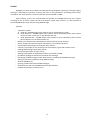
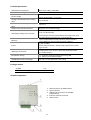
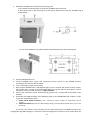
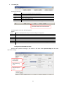
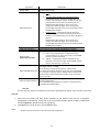
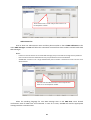
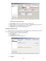
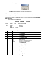
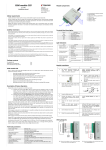
Gate controller GC1000 User Manual Orvos Monitooring OÜ E-mail: [email protected] Purpose of the document This document describes GC1000, its usage, features, and operation and how to set operation parameters. Contents GC1000 ....................................................................................................................................................... 3 Technical parameters.................................................................................................................................. 4 Package content ......................................................................................................................................... 4 GC1000 components................................................................................................................................... 4 Purpose of contacts ................................................................................................................................................ 5 Light indication ....................................................................................................................................................... 5 GC1000 installation ..................................................................................................................................... 5 Wiring diagrams.......................................................................................................................................... 7 Configuration using software Configurator ................................................................................................. 7 Connecting to a computer ...................................................................................................................................... 7 Configuration of GC1000 operation......................................................................................................................... 8 User list .................................................................................................................................................................. 9 Administrator list .................................................................................................................................................. 10 Recording and saving the configuration ................................................................................................................ 11 Updating the GC1000 firmware................................................................................................................. 11 Configuration and control using SMS messages......................................................................................... 12 Automatics control ................................................................................................................................... 14 Phone call ............................................................................................................................................................. 14 SMS message........................................................................................................................................................ 14 GC1000 SMS messages ............................................................................................................................. 14 Key terms ................................................................................................................................................. 16 Safety requirements ................................................................................................................................. 16 Warranty and limitation of liability............................................................................................................ 16 2 GC1000 GC1000 is a remote control device for electrotechnical equipment (opening or raising the gates, heating or ventilating the premises, watering the lawn or the greenhouse, controlling pump, boiler, transporter and other systems). Control commands are transmitted via GSM. Upon receiving a call to the inserted SIM card number, the GC1000 checks the user number according to the set mode, rejects the call and switches output relay contacts. It is also possible to switch GC1000 output relay contacts using SMS message. Features: 3 operation modes: a) mode All – GC1000 output relay contacts may be switched by any caller; b) mode Phone list – GC1000 output relay contacts may be switched by those, whose phone number is either on the user or the administrator list, c) mode Administrator – GC1000 output relay contacts may be switched by those, whose phone number is on the administrator list; Memory of 5 administrator and 1000 user names and their phone numbers, Phone number and name list export and import to, for example, MS Excel, Customisable switching period of output relay contacts, 2 inputs, for example, for the mounting case lock tamper or gate end position sensor, Sending SMS messages about input events, Customized description of input events, Sending confirmation of implemented control commands via SMS, Periodically sending an informative and detail test message, Distributing of SMS messages to the administrators according to GC1000 event types, Setting all operation parameters using SMS messages, Remote GC1000 reset, Ignoring unauthorised calls and SMS messages, Comprehensive and clear GC1000 operation light indication, Exceptionally simple to install and run. 3 Technical parameters GSM modem frequencies Power supply voltage Current usage Voltage commutated by the output relay Current commutated by the output relay Output relay control command Switching of output relay contacts Memory Inputs Working environment 850 / 900 / 1800 / 1900 MHz 12 … 36 VDC Standby 50 – 100 mA While sending SMS – up to 0,5 A up to 30 VDC up to 1 A By phone call or SMS message impulse (control command commutates the output relay from 1 to 60 seconds), level (control command commutates the output relay until the next control command, e.g., next phone call) Up to 5 administrator names and their phone numbers Up to 1000 user names and their phone numbers 2 (IN1 and IN2), Set for NO (resistance ≥ 10 kΩ) or NC (resistance ≤ 0,5 kΩ) type circuits Temperature from -10C to +50C with humidity of 93% (no condensation) Parameters setting a) Computer software Configurator using USB b) Special syntax SMS messages GC1000 dimensions and weight 79 x 65 x 25 mm aluminium case, 120 g Package content GC1000 Adhesive mounting tape (10 cm) 1 pc. 1 pc. GC1000 components 1. SMA connection of GSM antenna 2. Light indicators 3. USB Mini-B connection for GC1000 programming 4. External contacts connector 5. SIM card slot 4 Purpose of contacts Contact +E COM IN1 ir IN2 NC C NO Description Power supply + terminal Power supply – terminal and common terminal for IN1, IN2 inputs Terminals for input circuits 2 unused terminals Output relay NC terminal Output relay common C terminal Output relay NO terminal Light indication Indicator NETWORK (denotes communication between the GC1000 and GSM network) TROUBLE (denotes GC1000 operation) POWER (denotes GC1000 power supply) Status OFF Yellow flashing Green light (5 sec.) + N green flashes OFF Green light Red light (5 sec.) + red flashes: 1 flash 2 flashes 3 flashes 4 flashes 5 flashes 6 flashes 7 flashes 8 flashes OFF Green light Yellow light Yellow flashing Description GC1000 initialisation in progress Registration to GSM network in progress N - relative GSM signal level. 3 flashes – minimum sufficient level (30%), 10 flashes – maximum (100%). No faults Programming mode Insufficient power supply voltage, below 9 V No SIM card PIN code error Registration to GSM network failed for 60 seconds Operation mode setting error * Threshold GSM signal level (~ 30%)** Critical error in the parameters structure Error in the user phone number list structure No power supply Normal power supply Low supply voltage, below 11,5V Insufficient power supply voltage, below 9 V Notes: * - not a single administrator phone number is entered and the user list is prohibited. ** - use a portable GSM antenna with a cable and fit it to the exterior of the case if GC1000 is mounted into the metal case of automatics. GC1000 installation Follow this GC1000 installation procedure in order to ensure that GC1000 will be available for use to everyone with whom SIM card phone number is shared. 1. Purchase GC1000. Factory settings should not be changed! 2. Insert the SIM card of the desired network provider into the GC1000. - It is not recommended to use pre-paid contract SIM cards. SIM card PIN code must be disabled. SIM card must be already registered in the network. 5 3. Embed the GC1000 into the automatics mounting case. a) Use adhesive mounting tape to mount the GC1000 inside of the case. b) Drill three holes in the mounting case (see picture below) and screw the GC1000 using to screws M3x6. c) Insert the GC1000 into the plastic holder PH which fitted inside the mounting case. 4. Screw the GSM antenna on. 5. Connect GC1000 power supply and automatics control circuits to the GC1000 contacts according to the schemes laid out below. 6. Turn on the power supply of the system. 7. Wait until the GC1000 starts, LED Network lights up for 5 seconds and flashes at least 3 times, LED Trouble does not light up and LED Power lights up in green without interruption. If these indications are not as such, see section “Light indication“. 8. Check if the automatics can be controlled using a phone call – call the SIM card number of the GC1000. 9. Send these two SMS messages in the following order to the GC1000 SIM card number in order to gain the administrator status: 1) 123456 SETAP APNR1:+372xxxxxx (+372... setting the phone number as administrator phone number) 2) 123456 PSW 654321 (example of a SMS message setting a new password. 654321 refers to your new password) If you wish your system to be controlled only by authorised persons, GC1000 will need to be configured using SMS messages or computer software Configurator via USB. For more information see 6 sections “Configuration using software Configurator“ and “Configuration and control using SMS messages“. Wiring diagrams Inputs connection When NC input type is set (normally closed circuit) When NO input type is set (normally open circuit) Event is recorded when INx-COM circuit is broken Event is recorded when INx-COM circuit is connected Configuration using software Configurator All GC1000 operation parameters are set using computer software Configurator. Connecting to a computer 1. Connect the GC1000 to the computer USB slot using a USB cable (e.g., USB type A to Mini-B 5pin cable). 5 V power supply from the computer via USB is sufficient for GC1000 programming. 2. Run Configurator. 3. Software will determine the connected device type in several seconds and will open a new window for programming. Device may be located manually, if it cannot be found automatically. 7 4. Click Read [F7]. Function of the keys: Read Write Open Save Help Disconnect Read current GC1000 operation parameters Record new GC1000 operation parameters Open an operation parameters file stored on a computer Save an operation parameters file on computer Open the GC1000 manual Disconnect the controlled from software Configurator Information about the connected device In the program status bar will be dispayed where: Done is displayed after every successful reading or saving action Status Product name MDO GC1000 serial number SN: GC1000 firmware boot loader version BL: GC1000 firmware version FW: GC1000 hardware version HW: Port number or name via which GC1000 is connected to software Configurator Status: User access level admin Configuration of GC1000 operation Set the main operation settings in the menu In the main meniu System setings set the main operation settings: Set the object identification Select operating mode Select the type of inputs 8 Parameter Object name Dial control from Type of inputs IN1, IN2 Send Test message in Output mode Output pulse duration Admi and SMS password Allow to restore defaults Description GC1000 identification name that will be featured in every GC1000 SMS message a) All – controlled by anyone calling the GC1000 SIM card number. b) From the phone numbers list and administrators – controlled by anyone calling the GC1000 SIM card number and having their phone number on User and Administrator lists. All other calls will be ignored. Administrators will be able to send control and configuration SMS messages. Also, only they will receive SMS confirmations of sent command and other GC1000 SMS messages. c) Administrators – controlled by anyone calling the controlled SIM card number and having their phone number on the Administrator list. All other calls will be ignored. Administrators will be able to send control and configuration SMS messages. Also, only they will receive SMS confirmations of sent command and other GC1000 SMS messages. Choosing of input circuit type either NC or NO Setting period of the sending of GC1000 test messages Output relay operation mode: a) Level – relay contacts status is switched to other command status, e.g. other phone call, once GC1000 receives a control command b) Impulse – relay contacts status is switched to the opposite to set impulse length, once GC1000 receives control command, e.g. a phone call Six-digit password for configuration and control using SMS messages. Default - 123456. Click Change to change the password to a desired one. Tick Allow to change to allow everyone who connects GC1000 to a computer to reset to factory settings. When unticked, the administrator password must be entered in order to reset to factory settings. Changing the current GC1000 configuration to the initial default factory configuration. Tick Remember the password for computer to remember the new Admi and SMS password. User list The list of users, which are allowed to control the equipment by phone call is made in the menu User list. 1. Enter the user names and their phone numbers in the fields of the user list in program Configurator. Alternatively, create the list of user names and their phone numbers in MS Excel and click Upload to upload the list to the program. 2. Click Save (F5) to save the list in the GC1000 memory. Note: Numbers must be entered in international format using prefix +. 9 The first enter User’s name and just then enter his or her telephone number Administrator list Enter at least one administrator name and their phone number in the tab SMS addressees in the menu SMS messages. GC1000 will follow the commands received from these numbers and will send them SMS messages. Notes: - If those on this list want to send control SMS messages, they must know the six-digit control password. Phone number of the first administrator may only be edited and cannot be deleted. GC1000 will not work if not a single administrator phone number is entered and control for the users will be denied. The first enter the Administrator’s name and just then enter his or her telephone number Select the encoding language for sent SMS message texts in tab SMS texts. Enter desired confirmation texts for SMS texts and commands. In case of an event, GC1000 will send the appropriate message with the customised text. 10 Texts of the SMS messages Recording and saving the configuration 1. Click Record [F6] to record your configuration into the GC1000 memory. 2. GC1000 configuration may be saved on the computer. Click Save [F5] and create a file for GC1000 configuration. Click Open [F3] to access it when needed. 3. Click Disconnect to disconnect the programmed device. Updating the GC1000 firmware Manufacturer may improve the operation of GC1000 and release a new GC1000 firmware version. Every user has an opportunity to update operation of their GC1000. 1. Connect the GC1000 to a computer using USB cable. 2. Run Configurator. 3. Select Firmware in the menu. 4. Click Find and select the desired firmware file. 5. Click Update. 11 6. Wait until the prompt appears. 7. Click OK. All operation settings will remain the same after the update. Configuration and control using SMS messages GC1000 parameters may be set and changed by sending SMS messages from a phone number, which is on the administrator list. In case there are not any entered administrator phone numbers, become an administrator by sending the following SMS message to the controlled SIM card number: 123456 SETAP APNR1:+372xxxxxxx. Structure of the command SMS message: PASSWORD SPACE COMMAND SPACE PARAMETERS Example: Here: 123456 SPACE SETAP SPACE APNR1:+37212300000 123456 SETAP APNR1:372 password command parameters Commands sent in SMS messages: No. Command 1 RESET 2 INFO 3 PSW 4 SETC Contents New password ALL LIST DISABLE 5 SETI NC NO 6 SETO 00 05 7 SETT 00 30 Description Resetting GC1000: E.g.: 123456 RESET Inquiring about the GC1000 status: E.g.: 123456 INFO Changing the GC1000 password: E.g.: 123456 PSW 654321 Permission to control by phone call: All callers (default); Only those on User and Administrator lists; Only those on the Administrator list . E.g.: 123456 SETC LIST Setting input IN1, IN2 types: Normally Closed (NC); Normally Open (NO); E.g.: 123456 SETI NO Output OUT operation: Switching level mode; Specified length (seconds) impulse; E.g.: 123456 SETO 05 Sending period of test messages: Do not send; Send during the specified hours; E.g.: 123456 SETT 30 12 8 SETH 00 10 9 SETL ENG LIT RUS 10 SETAP APNR1:+372xxxxxx APNR2:+372xxxxxx APNR3:+372xxxxxx APNR4:+372xxxxxx APNR5:+372xxxxxx APNR1:DEL APNR2:DEL APNR3:DEL APNR4:DEL APNR5:DEL 11 SETAE IN1 IN2 OUT TEST ACK 12 SETAN APNR1:Name APNR2:Name APNR3:Name APNR4:Name APNR5:Name APNR1: APNR2: APNR3: APNR4: APNR5: 13 TXTA 14 TXTE <Object name> IN1:<Text> IN2:<Text> OUT:<Text> 15 TXTR IN1:<Text> Answering phone calls: Reject before answering (default); Answer the call and hold for the specified period of time; E.g.: 123456 SETH 05 Setting the communication language: English (default); Lithuanian; Russian; E.g.: 123456 ENG Enetering administrator phone numbers: 1st phone number; 2nd phone number; 3rd phone number; 4th phone number; 5th phone number; E.g.: 123456 SETAP APNR1:+372xxxxxx Deleting administrator phone numbers: 1st phone number; 2nd phone number; 3rd phone number; 4th phone number; 5th phone number; E.g.: 123456 SETAP APNR2:DEL Allocation of messages to administrators: Sending IN1 input events; Sending IN2 input events; Sending control events; Sending test messages; Sending responses to command SMS E.g.: 123456 SETAE APNR1:IN1-ON,IN2-ON,OUT-ON,TEST-OFF,ACK-ON Entering an administrator name: Entering the name of the 1st administrator; Entering the name of the 2nd administrator; Entering the name of the 3rd administrator; Entering the name of the 4th administrator; Entering the name of the 5th administrator; E.g.: 123456 SETAN APNR2:Name Deleting an administrator name: Deleting the name of the 1st administrator; Deleting the name of the 2nd administrator; Deleting the name of the 3rd administrator; Deleting the name of the 4th administrator; Deleting the name of the 5th administrator; E.g.: 123456 SETN APNR2: Entering an object name: E.g.: 123456 TXTA object name Entering an event message text: IN1 input event; IN2 input event; OUT output event; E.g.: 123456 TXTE IN1:1st input event Entering a restoration event message text: IN1 input restoration; 13 IN2:<Text> OUT:<Text> 16 SETP +372xxxxxx +372xxxxxx,<Name> 17 DELP +372xxxxxx <Name> 18 OUT ON OFF IN2 input restoration; OUT output restoration. E.g.: 123456 TXTR IN2:2nd input restore Entering a user name and their phone number: User phone number; User phone number + name. E.g.: 123456 SETP +372xxxxxx E.g.: 123456 SETP +372xxxxxx,Name Deleting a user phone number: User phone number; User name E.g.: 123456 DELP +372xxxxxx E.g.: 123456 DELP Name Changing the outputstatus: Changing output status to ON; Changing output status to OFF. E.g.: 123456 OUT OFF Automatics control Phone call 1. Call to the GC1000 using a SIM card number. 2. Control command will be implemented immediately after the GC1000 rejects the call. SMS message Note: Phone number must be on the GC1000‘s administrator list. 1. Send SMS message: Example: 123456 OUT OFF to turn the output relay to the state off; Example: 123456 OUT ON to turn the output relay to the state on; 2. Wait until you receive the confirmation of command implementation (if specified during the configuration): Command OK command implemented; Wrong Password wrong password; Wrong Command wrong command; Wrong Data wrong parameters; Fatal Error GC1000 error (this response cannot be described by the user) GC1000 SMS messages GC1000 will send SMS messages to the administrators once a GC1000 event takes place or GC1000 receives a control message via SMS. Every time 12 V power supply voltage is turned on, administrators are send a SMS message: SMS text Dev: IMEI: 863071014319393 SN: 000002 FW: 0.02 ENGLISH Description Device name IMEI code of the GSM modem Serial number of the GC1000 GC1000 firmware version SMS text encoding 14 Administrators are send a test SMS message in a time period specified during the configuration: Text Meaning Description MDO Object name entered in the field Object name Power: 24,5V Power supply in voltage Signal: 90% Signal level in percent IN1: IN1 input status: OK circuit intact False circuit is broken IN2: IN2 input status: OK circuit intact False circut is broken OUT: Output relay status: ON ON OFF OFF Used Phone: Admin: x/5 x phone numbers out of 5 possible entered User: x/1000 x phone numbers out of 1000 possible entered Fatal ERROR!!! GC1000 is ignoring the phone numbers list due to errors Example of a SMS message response to the SMS inquiry: Text Meaning Description GC1000 Object name Object name specified during the configuration is displayed in the message Input1 Event Event in input IN1 GC1000 event SMS text specified during the configuration is circuit displayed in the message 15 Key terms Input event – change of the resistance (exceeding the specified limits) in the circuit between outputs IN and COM. NC (Normally Closed) – type of circuit between outputs IN and COM. Resistance in the circuit between the contacts is low (circuit is closed) in normal state, i.e. resistance is not higher than specified. Increase in resistance above the specified limit will trigger a message about the event. NO (Normally Open) – type of circuit between outputs IN and COM. Resistance in the circuit between the contacts is high (circuit is open) in normal state, i.e. resistance is not lower than specified. Decrease in resistance below the specified limit will trigger a message about the event. Safety requirements Be sure to familiarise yourself with this manual before using the GC1000. GC1000 may only be set up and maintained by trained specialists, who possess knowledge about operation of GSM devices and their safety requirements. External power supply must be turned off when controlled is being set up! GC1000 must be set up in limited access areas and in safe distance from sensitive electronic equipment in the premises. GC1000 is not resistant to vibration, other mechanical effects, humidity and aggressive chemical environment. Cases, transformers and other used devices must comply with LST EN60950 standard safety requirements. GC1000 is powered by 12-36 V DC power. A bipolar automatic fuse must be set up to protect from a too high electric current supply in the circuit. Separation gap between the contacts must not be smaller than 3 mm. The fuse must be set up in a place known to the maintenance specialists. Device is disconnected from the electrical network by turning off the automatic fuse. Warranty and limitation of liability The manufacturer provides a 24 month warranty. Warranty coverage begins on the day of the product purchase-sale agreement or on the issue date of an invoice or a fiscal check. The manufacturer is not liable for product malfunction, if the product is set up or used not in accordance to the product user manual. The manufacturer is not liable for product malfunctions, if they have occurred due to the loss of GSM/GPRS/Internet connection or due to failure in the networks of the connection service provider. The manufacturer is not liable for the interruption or restriction of GSM/GPRS/Internet connection service to the product buyer or the user of the product and shall not reimburse the resulting property or non-pecuniary damages. The manufacturer is not liable for the interruption or restriction of the electricity supply to the product buyer or the user of the product and shall not reimburse the resulting property or non-pecuniary damages. 16