1
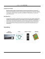
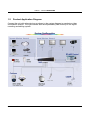
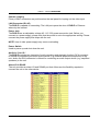
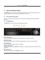
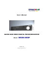
User´s Manual
AUDIO AND VIDEO DIGITAL RECORDER-EDITOR
Model:
DE200-00DP
Version 1.4a
Copyright © 2008 DynaColor, Inc.
DVR-E - Model: DE200-00DP
Contents
1.
2.
3.
4.
5.
6.
Overview ..................................................................................................................................................... 5
1.1
Product Key Features ........................................................................................................................... 6
1.2
Product Application Diagram ................................................................................................................ 7
System Setup ............................................................................................................................................... 8
2.1
Position the Unit .................................................................................................................................. 8
2.2
Selecting Video Format......................................................................................................................... 8
2.3
Connecting Devices to the Unit............................................................................................................. 8
2.4
Rear Panel Connections ....................................................................................................................... 9
General System Setup ................................................................................................................................ 12
3.1
Front Panel Introcuction ..................................................................................................................... 12
3.2
Led Definition ..................................................................................................................................... 12
3.3
Funcional Keys.................................................................................................................................... 13
3.4
Install HDD to The Unit ....................................................................................................................... 17
Setup Sequence ......................................................................................................................................... 18
4.1
Sequence with Main Monitor ............................................................................................................. 18
4.2
Sequence with Call Monitor ............................................................................................................... 18
4.3
Searching Recorded Video .................................................................................................................. 19
4.5
Searching by Event ............................................................................................................................. 20
4.6
Audio and Video Edit .......................................................................................................................... 20
4.9
ezBurn Introdution ............................................................................................................................. 21
Audio & Video Edit ..................................................................................................................................... 22
5.2
Deleting Recorded Video .................................................................................................................... 24
5.4
Dome Connections ............................................................................................................................. 25
5.5
Dome Controlling Key ......................................................................................................................... 26
5.6
Setting Preset Points .......................................................................................................................... 27
Edit ............................................................................................................................................................ 29
Appendix A: Audio and Edit Connection ............................................................................................................. 30
All of the specifications of this manual are subject to changes without notification.
User´s Manual
2
DVR-E - Model: DE200-00DP
Caution and Preventive Tips
• Take care not to drop the unit or subject the unit to major shocks or jolts.
• Do not place this unit on an unstable stand, bracket or mount.
• This unit is designed for indoor use only. Do not place the unit near water or in other extremely
humid conditions.
• This unit should not be placed in a built-in installation unless proper ventilation is provided.
• Please check the used type of power source before you plug and operate the unit.
• If the clearing is necessary, note to plug the unit from the outlet before uncovering the top cover. Do
not use liquid cleaners or aerosol cleaners. Use only a damp cloth for cleaning.
• Always power down the system prior to connecting and disconnecting accessories, with the
exception of USB devices.
• Lithium battery: Danger of explosion if battery is incorrectly replaced. Replace with the same or
equivalent type recommended by the battery manufacturer. Dispose of used batteries according to
the battery manufacturer’s instructions.
• Do not block the fan on the bottom of the unit for air ventilation.
This symbol intends to alert the user to the presence of important operating
and maintenance (servicing) instructions in the literature accompanying the
appliance.
This symbol intends to alert the user to the presence of unprotected
“Dangerous Voltage” within the product’s enclosure that may be strong enough
to cause a risk of electric shock.
User´s Manual
3
DVR-E - Model: DE200-00DP
Important Information
Before proceeding, please read and observe all instructions and warnings in this manual.
Retain this manual with the original bill of sale for future reference and, if necessary, warranty
service. When unpacking your unit, check for missing or damaged items. If any item is missing,
or if damage is evident, DO NOT INSTALL OR OPERATE THIS PRODUCT. Contact your
dealer for assistance.
Rack Mounting
Consult with the supplier or manufacturer of your equipment rack for the proper hardware and
procedure of mounting this product in a safe fashion. Avoid uneven loading or mechanical
instability when rack-mounting units. Make sure that units are installed to get enough airflow for
safe operation. The maximum temperature for rack-mounted units is 40 °C. Check product
label for power supply requirements to assure that no overloading of supply circuits or over
current protection occurs. Mains grounding must be reliable and uncompromised by any
connections.
Unpacking
DVR-E
DE200-00DP
User´s Manual
Cable
Remote Control
Manuals
4
DVR-E - Model: DE200-00DP
1.
Overview
The Audio and Edit Digital Recorder-Editor model DE200-00DP is pioneering in the
characteristic Stand Alone gathering the resources of the technology of digital recording with
audio edition and video.
The DVR-E model DE200-00DP allows that an external audio to be added through the
channels audio (R and L), modifying the original audio of the a video. For this audio edition
a microphone can be used for insert of speeches and sound adapts or until yours sound
equipment, make possible the insert of the yours favorite music or even the propaganda of
a product or mark.
In the DE200-00DP, the video can be edited and only sent with main parts without the need of
the sending the complete video.
The DE200-00DP is adapted for a wide range of applications in systems of to 16 cameras and
2 audio channels.
The DE200-00DP has friendly graphic Interface that allows simple and intuitive operation.
User´s Manual
5
DVR-E - Model: DE200-00DP
1.1
•
•
•
•
•
•
•
•
•
•
•
•
•
•
•
•
•
•
•
•
•
•
•
•
•
•
Product Key Features
Audio and Video Edit
MPEG-4 high quality compression
16 channels video input
Triplex+ operation enabling simultaneous viewing live or playback while continuing to
record
Embedded Linux operating system
Real-time “live display” for each channel
Recording frame rate up to 480 pps (NTSC) / 400pps (PAL)
2 Channels of audio recording/ playback
Three USB2.0 ports for video clip export and/or backup
Easy software upgrade via USB ThumbDrive®, DVD+RW, or Internet
Remote Application
Up to 4 internal hard disk drives support up to 1TB capacity
Hard disk drive full alarm for noticing
2X Digital Zoom available in live mode
Export video (AVI & DRV) with audio and digital Signature
Exported AVI file can be played in any PC with DivX decoder installed
Automatic camera detection (Plug & Play)
Covert camera operation provides enhanced security and administrator Control
Per camera configuration for camera settings, frame rate, picture bit rate, alarms, motion
detection.
Programmable day/ night/ weekend scheduling
Programmable main monitor/ call-monitor switching sequence
Dual video out for monitoring
Powerful alarm processor allows flexible alarm trigger and responses,
including alarm, motion, and camera failure
Text Message (Short Message Service; SMS) sent to your mobile phone for alarm
notice.
Dome control protocols: DynaColor, Pelco D, Pelco P,AD422 and Fastrax 2.
Pre-program the OSD menu using a mouse connected to the USB port
User´s Manual
6
DVR-E - Model: DE200-00DP
1.2
Product Application Diagram
Connect the unit with other devices as shown in the system diagram to complete a video
surveillance solution. The figure shows also the expandability and flexibility of this digital
recording and editing system.
User´s Manual
7
DVR-E - Model: DE200-00DP
2.
System Setup
The notices and introduction on system installation will be described particularly in this chapter.
Please follow the description to operate the unit.
In order to prevent the unit from data loss and system damage that caused by a sudden power
fluctuation, use of an Uninterruptible Power Supply (UPS) is highly recommended
2.1
Position the Unit
Firstly, note to position / mount the DVR-E in a proper place and be sure to power off the unit
before making any connections. The placed location should avoid hindering or blocking the
unit from airflow.
Enough airflow is needed to protect the unit from overheating. The maximum allowable
temperature of operating environment is 40°C.
The unit utilizes heat-conducting techniques to transfer internal heat to the case, especially to
the bottom side of the unit.
NOTE:
2.2
Be sure not to remove the rubber feet, and always leave a space for air ventilation
on the unit’s bottom side.
Selecting Video Format
The DVR-E is designed to operate under either NTSC or PAL video formats. The switch is
positioned on the rear panel.
2.3
Connecting Devices to the Unit
This section lists some notices that should be given before making any connections to the
DVR-E.
NOTE:
Connect short-term devices, such as USB ThumbDrive®, USB CD-RW, USB Hard
Disk Drive, etc., only after the unit is successfully powered up.
Connecting Required Devices
Before power up the unit, you should connect cameras and a main monitor to
the unit for basic operation. If needed, connect a call monitor for displaying full
screen video of all installed cameras in sequence.
User´s Manual
8
DVR-E - Model: DE200-00DP
Connecting Short-term Device
If you plan to install any short-term devices to the DVR-E and use them as part of the unit
system, such as USB CD-RW, USB Hard Disk Drive, etc. Make sure connecting those devices
only during the unit is powered up. Because DVR-E can recognize the external devices only
after the power-up process is done completely.
2.4
Rear Panel Connections
There are various connectors on the rear panel used for DVR-E installations. The following
figure shows the connectors by name; and followed by the detailed description of each
connector.
Main Monitor (S-Video / BNC)
Both S-Video and BNC output connectors are offered for connecting to a main monitor. The
main monitor displays live image and playback recorded video in full-screen or split-window
format.
Call Monitor (BNC)
The call monitor is used to display full screen video of all installed cameras in sequence. The
BNC call monitor connector allows user to connect the DVR-E with an optional call monitor.
Video Input
16 BNC connectors are offered for video input streams from installed cameras.
The number of connectors is equal to the number of channels.
User´s Manual
9
DVR-E - Model: DE200-00DP
Camera Looping
Plenty of BNC connectors are positioned on the real panel for looping out the video input.
LAN Connector (RJ-45)
The DVR-E is capable of networking. The LAN port opens the door of DVR-E to Ethernet
where by the Internet.
Power Jack
The DVR-E has an adjustable voltage AC 115 / 230 power connection jack. Before you
connect to a power supply, please note that the switch is set to the appropriate setting. Please
connect the power supply that ships with the unit.
NOTE: Use of other power supply may cause overloading.
Power Switch
Used to power up and shut down the unit.
Audio In / Out115 /
The DVR-E provides two channels of audio recording and playback. Audio In RCA connector
is offered for connecting an audio source device (e.g. external amplified microphone) to the
unit; Audio Out RCA connector is offered for connecting an audio output device (e.g. amplified
speakers) to the unit.
Alarm I/O & RS485
The unit provides an alarm I/O and RS485 port that offers user the flexibility required to
connect the unit to the other device.
User´s Manual
10
DVR-E - Model: DE200-00DP
VGA Out
A VGA output connector is offered for connecting to a VGA main monitor. The source of image
of VGA and BNC main monitor are the same.
RS-232C
The unit provides a RS-232C communication port for sending and receiving signals.
USB Connector (x2)
There are two USB2.0 ports on the rear panel for users to connect external
USB devices to the unit, such as ThumbDrive® or CD-RW.
DVR-E allows users to preset the OSD settings using a USB mouse.
User´s Manual
11
DVR-E - Model: DE200-00DP
3.
General System Setup
The DVR-E allows user to access some general operations through the front panel easily. The
following subsections introduce the general operations of the unit.
3.1
Front Panel Introcuction
The unit’s front panel controls enable user to control the unit and preset the programmable
functions.
3.2
Led Definition
The DVR-E LEDs on the front panel are described as follows.
Power Network
Alarm
REC
HDD
Power LED (Green)
The LED lit during the period when the correct power is connected to the unit.
HDD LED (Yellow)
The LED should be lit while the HDD is processing data to or from the connected HDD.
Alarm LED (Red)
The LED should be lit during an alarm is triggered.
Network LED (Green)
The LED should be lit when DVR-E is connected to a network and blink when the data is being
transferred.
REC LED (Green)
The LED should blink while the DVR-E is recording.
User´s Manual
12
DVR-E - Model: DE200-00DP
3.3
Funcional Keys
The DVR-E functional keys on the front panel for normal operation are described as follows.
.
Dome Mode
Channels
Call
Play/Stop
SEQ
Freeze
Menu
Search
ESC
Zoom/Enter
Direction Buttons
Shuttle Jog
CALL
• In Live mode, press to enter call monitor control mode.
• In Playback mode, press to quick export video to external device, including USB CD-RW
and ThumbDrive®, etc.
Direction Keys
• In Zoom mode, these keys function as Direction keys.
• In the OSD setup menu, the Direction keys are used to move the cursor to previous or next
fields. To change the value in the selected field, press UP / DOWN keys.
UP
RIGHT / DOWN / LEFT
Dome
Press the key to enter dome control mode.
User´s Manual
13
DVR-E - Model: DE200-00DP
ESC
• Press to cancel or exit from certain mode or OSD menu without changing the settings
made previously.
• This key allows you to enable the key lock function.
If the password protection has been enabled, press ESC for two seconds
to lock up the function of certain keys on the front panel, including PLAY, MENU, SEARCH,
CALL and DOME. Once you lock up the function of these keys, you have to enter the
correct password before accessing the functions of these keys. The unlocking duration will
list for 5 minutes, then these keys will go back to locked mode.
If the password protection hasn’t been enabled, press ESC for two second to lock/ unlock
the functions of these keys.
NOTE: Please go to the <Password> menu to enable or disable the password protection.
MODE
Press repeatedly to select for wanted main monitor display format. There are three available
view modes: full screen, 4-window (2×2) and 16-window (4×4).
User´s Manual
14
DVR-E - Model: DE200-00DP
PLAY/ STOP
Press this key to switch between live image and playback video.
NOTE:
The video of latest 5 ~ 10 minutes cannot be played back, because the video is still
saved in the buffer.
FREEZE
• Press FREEZE while viewing live image, the live video will be frozen. The date / time
information shown on the monitor will continue updating. Press FREEZE again to return to
live mode.
• Press FREEZE while playing the recorded video, the playback video will be paused. Press
LEFT / RIGHT to move the recorded video reverse / forward by single step. Press FREEZE
again to continue playing video.
SEQ (Sequence)
Press to start automatic sequencing of the video coming from the installed cameras.
SEARCH
In both Playback and Live mode, user can press SEARCH to call the Search menu for
searching and playing back recorded video by date and time or events.
MENU
Press the key to call the OSD setup menu.
ZOOM / ENTER
• In OSD menu or selection interface, press the key to make the selection or save settings.
• In live full screen view mode, press to view a 2× zoom image; press it again to return.
CHANNELS
• When in both Live and Playback modes, press the CHANNEL key to view the corresponding
video in full screen. The number of the CHANNEL keys corresponds to the number of cameras
supported by the unit.
• When in dome control mode, the key named “1” is used to access the Set/Go preset menu;
the key named “2” is used to hide or display the dome setting parameters.
User´s Manual
15
DVR-E - Model: DE200-00DP
JOG / SHUTLLE
The jog/shuttle knob, shown as below figure, is a combination of a shuttle ring with an
embedded jog disk, which is used to provide wide latitude in playback control. Note that the
jog/shuttle knob is active only when the DVR-E unit has been in Playback mode.
While playing back video, you can use the shuttle ring to select different speed of forward and
backward playing. Rotating the shuttle ring counterclockwise causes the unit to playback into
faster forward/ backward playing speed. According to the angle you rotate the shuttle ring, you
can choose the playing speed from 1×, 2×, 4×, 8×, 16×, and 32×, in both forward and reverse
directions, shown as below figure:
Inside the shuttle ring is the jog disk, shown as the figure, it can turns completely in either
directions. Once you freeze the video, you can use the jog disk to go single-step playing back.
Clockwise rotation causes a forward one-step playback; and counterclockwise rotation causes
a backward one-step playback.
User´s Manual
16
DVR-E - Model: DE200-00DP
3.4
Install HDD to The Unit
There is a cartridge positioned on the front panel, and it allows user to install a swappable
HDD. There will be two possible situations when you install a HDD into your DVR-E.
•
If you install whole new HDDs, the DVR-E will format it and add it into your database
automatically.
•
If you install an used HDD which doesn’t have the DVR-E format, the DVR-E will show up
“1 disk(s) with wrong data format! Please format them and then add to the database
manually”. Then please follow the steps as wedescribe below:
- Please enter the menu with the administrator privilege and access the“Database
Information” section
- Please access the “Internal(or external) Disks”
- You can see the available disks, please select “format” to format it
- After formatting is OK, please select “Add” to add them into your database.
User´s Manual
17
DVR-E - Model: DE200-00DP
4.
Setup Sequence
This section introduce you how to view in sequence mode with both Main Monitor and Call
Monitor, if connected. Sequence function can avoid manually backtracking and give more
flexibility while surveillance.
4.1
Sequence with Main Monitor
Automatic sequence function can be used in any view mode. Select certain view format and
press SEQ to toggle the automatic sequential sequence, press ESC to stop sequencing. The
figure below displays the 4-camera and 9-camera sequencing view modes.
4.2
Sequence with Call Monitor
Users are allowed to use the DVR-E front panel to control a call monitor display without having
to access the Main menu. Two viewing modes can be displayed on call monitor: Sequence
display and Single camera display.
Follow the steps to control the call monitor.
• Press the CALL key on the front panel to enter call monitor control mode, the message “Call
Mode” will be shown on the bottom-left of the screen.
Press 1-16 Key To Select Channel
Press SEQ To Enable Sequence
<CALL MODE>
User´s Manual
18
DVR-E - Model: DE200-00DP
• Press CHANNEL key to display the associated camera on call monitor.
• Alternatively, press SEQ repeatedly to display the sequence of cameras previously
programmed in Call Monitor Schedule menu.
• Press ESC to return the front panel to Main monitor control mode.
4.3
Searching Recorded Video
The DVR-E is capable of searching and playing back recorded video by date and time or
events. Entering the specific date and time of the wanted video, the unit will then search for the
matched video and play it on the monitor. Alternatively, user can search event video by
selecting channel as well.
In live or playback mode, press SEARCH to enter the Search menu, which is shown as follows.
4.4 Searching by Time
Follow the steps to search video by date and time.
•
•
•
•
•
Press SEARCH key to enter the Search menu; the From Time and End Time of the
available video is listed on top of the screen. The value is unchangeable.
Use Direction keys to move the cursor for setting the Start Time; adjusting the date and
time values by UP / DOWN keys.
Press ENTER to confirm the settings or ESC to abort.
Move the cursor to <Begin Playback> and press ENTER to start playing back the selected video.
Either press PLAY/STOP again or ESC to return to live video.
NOTE: If there is no available recorded video that matches your specified time and date, the
unit starts playback from the next available video.
NOTE: The date/time information will be shown on the screen with a DST icon if the Daylight
Saving Time function is enabled. “S” indicates summer time and “W” indicates wintertime.
User´s Manual
19
DVR-E - Model: DE200-00DP
4.5
Searching by Event
“Event List” allows you to search wanted video by event. The Event List is displayed as below
figure:
Follow these steps to search event video through Event List:
• Press SEARCH to enter the Search menu.
• To search event video that has been recorded on a specific camera, use LEFT / RIGHT to
move the cursor and press ENTER to select or de-select a channel.
• Move the cursor to <Event List> and press ENTER to list the event video of the selected
channels. The Event List displays.
• To exit the event list, press ESC. Follow the steps to playback video from Event List.
• Press and hold UP / DOWN to scroll through the Event List.
• Press ENTER to play back the selected event record.
• Press PLAY/STOP to return to live mode.
4.6
Audio and Video Edit
The following sections will guide you how to export video throng the OSD Setup menu and
through the hot keys positioned on the front panel, respectively.
User´s Manual
20
DVR-E - Model: DE200-00DP
4.9
ezBurn Introdution
Built with the ezBurn technology, ezBurn function provides users the easier way to export
desired video with CD-RW built in or to an external device connected, such as an USB
ThumbDrive®.
TWO keys (SEARCH and CALL) and THREE touches are all you need for completing the
export. The whole exporting process will be done through the front panel, but no need to enter
the OSD setup menu.
The ezburn export process is illustrated as below figure:
User´s Manual
21
DVR-E - Model: DE200-00DP
5.
Audio & Video Edit
The Audio &Video edit menu enables the administrator to export recorded video with digital
signature to a USB ThumbDrive®, a CD-RW or to DVD+RW drive. Administrator's password is
required to edit audio and video.
The edited video will be named by the exporting date and time, and classified by event type.
Make sure an external storage device is available and connected to the appropriate port for
audio and video edit.
From the Main menu, select <Audio & Video Export> and press ENTER. The menu is
displayed.
Audio & Video Export
1. Export Edit File to Device
2. Select Ch:
CH1 CH2 CH3 CH4
3. From
2005/03/19 AM 07:50:05
4. To
2005/03/28 PM 03:09:18
5. Select Events
6. Type of Edit Data Exported
Normal
7. Edit Data Format
AVI
9. Erase Disc
NO
10. Enable Editor
Audio
User´s Manual
22
DVR-E - Model: DE200-00DP
Select Export Edit File to Device
The available external devices for exporting video will be listed by name and free size in Select
Device menu. The Select Device menu displays as follows.
The DVR-E only supports EXT3 file system. If you connect an external HDD to the unit,
ensure the format of HDD is EXT3.
Device Name
The item shows the name of the available device.
Available
The item shows the free space of the available device.
Select
Set the item to <YES> to start the export, or <NO> to cancel.
Select Channel
Select the channel that the administrator wants to export. Move the cursor to the wanted
channel using LEFT / RIGHT keys, select or de-select a channel by pressing ENTER.
From / To Time
The items are used to set the time which data edit begins and ends. Move the cursor using
Direction keys, and press ENTER to select the date / time items; adjust the selected date and
time value by UP / DOWN keys.
NOTE:
The edit data between the Start Time and End Time includes both normal and event
video.
Select Events
Select the item to display the event list for exporting event video. Move the cursor scroll the
event list and press ENTER to select the event you want to export.
User´s Manual
23
DVR-E - Model: DE200-00DP
Type of Edit Data Exported
The item is used to select exporting video type. The options are <Normal> (export normal video
only), <Event> (export event video only) and <Both> (export both normal and event video).
NOTE: If you want to export event video only, then please set the “From” and “To” items at the
same date and time. Otherwise, not only the event video but also the normal video
included between the “From” date/ time and “To” date/time will be exported.
Edit Data Format
The item is for selecting exporting video format. The options only <AVI>.
Enable Editor
Select <Both> , <Audio> or <Video> and press ENTER to start to edit.
Quick Video Export through Front Panel
The unit allows you to export wanted video to the built-in CD-RW or an external device, such
as a USB ThumbDrive®, and save the video to *.drv file.
If you want to export video to an external device, make sure the external storage has been
connected to the DVR-E unit and the port has been set appropriately for video export.
5.2
Deleting Recorded Video
User can delete the recorded video in Purge Data menu. The administrator password is required
to access the function. Select <Record Setup> from Main menu, and then in Record Setup menu,
move the cursor to <Purge Data> and press ENTER; the Purge Data menu is displayed.
Purge Data
1. Purge All Data
2. Purge All Event Data
3. Purge Event Before
4. Start to Purge
NO
NO
2000/01/01
NO
The first three items are used to select the data that you want be purged. The items are
described as follows. After select the data you want to purge, set the forth item <Start to
Purge> to <YES> and press ENTER to start the deleting process.
Purge All Data
Select the item to delete all normal recorded video from database.
Purge All Event Data
Select the item to delete all event video from database.
Purge Event Before
The item is used to delete event video that recorded before a specific date.
User´s Manual
24
DVR-E - Model: DE200-00DP
5.3 Dome Control
The DVR-E allows user to control a dome camera by the front panel.
In Live mode, user can press CHANNEL key to display the desired dome camera in full view.
To enter Dome Control mode, press the DOME key and press channel key 2 to display the hint
screen; to exit the Dome Control mode and back to live mode, press ESC or DOME.
5.4
Dome Connections
Follow the steps to install dome camera.
•
See OSD Menu Setup Guide, Section Rear Panel Connections for RS-485 port pin
definition.
•
Refer to the following figure. Connect the R+, R- terminals on the dome camera to
the D+, D- terminals on the RS-485 port by RS-485 cable respectively.
User´s Manual
25
DVR-E - Model: DE200-00DP
5.5
Dome Controlling Key
The function keys used in Dome Control are described as follows.
Set/Go
Preset
Toggle Hint
Screen
Iris
Focus
Open Near
Iris Focus
Close
Far
Zoom
In
Zoom
Out
ESC
Enter/
Auto
Pan/Tilt
Set / Go Preset
This key is used to enter the Dome Preset menu to set up certain position as a preset and go
to the predetermined preset positions for viewing.
Toggle Hint Screen
This function is used to avoid viewing the dome parameter information while controlling dome
camera. Press this key to hide the screen. Press it again to redisplay the screen.
Iris Open
Use to open the Iris on the dome camera.
Focus Near
Use to focus the dome camera near.
Zoom In
Use to zoom the dome camera in. This function is for user to choose the viewing area, more or
less of it.
ESC
Use to leave dome control mode and return to live and full screen viewing mode.
Auto / Enter
• In OSD Menu mode, the key is used to make selection.
• In dome control mode, this key is used to activate automatic focus and iris function.
User´s Manual
26
DVR-E - Model: DE200-00DP
Iris Close
Use to close the Iris on the dome camera.
Focus Far
Use to focus the selected dome camera far.
Zoom Out
Use to zoom the dome camera out. This function is for user to choose the viewing area, more
or less of it.
5.6
Setting Preset Points
The DVR-E allows user to set preset positions; the amount of preset points depends on the
dome manufacturer.Follow the steps to set preset points.
• Press a Channel key to view the corresponding camera in full screen.
• Then press DOME to enter dome control mode. And a Hint Screen, shown as blow figure,
displays on the screen.
• Press 2 again to hide the dome control Hint Screen; press 2 one more time to toggle the
Hint Screen.
• Use Direction keys to position the dome camera to desired position.
Hint Screen
DOME / ESC: Sair
MODE / PLAY: Íris Aberta / Fechada
SEQ / FREEZE: Focus In / Out
MENU /SEARCH: Zoom In / Out
ENTER: Auto focus / Íris
: Pan / Tilt
CH1: Gravar / Visualizar Pré-posição
CH2: Ativar / Ocultar Tela
<Controle Dome>
User´s Manual
27
DVR-E - Model: DE200-00DP
• Press 1 to access the Set/Go Preset function. The Dome Preset menu is displayed.
Index
1
2
3
4
5
6
7
Dome Preset
Set Preset
NO
NO
NO
NO
NO
NO
NO
Go Preset
NO
NO
NO
NO
NO
NO
NO
•
Use UP / DOWN keys to select the desired preset number from the menu.
•
Set the <Set Preset> of the selected preset number to <YES>, and press ENTER to save
the position. Now the preset is set and ready to call.
Calling Preset Points
Follow the steps to call preset points.
• Press a Channel key to view the corresponding camera in full screen.
• Then press DOME to enter dome control mode. And a Hint Screen, shown as blow figure,
displays on the screen.
• Press 2 again to hide the dome control Hint Screen; press 2 one more time to toggle the
Hint Screen.
• Press 1 to access the Set/Go Preset function.
Index
1
2
3
4
5
6
7
Dome Preset
Set Preset
NO
NO
NO
NO
NO
NO
NO
Go Preset
NO
NO
NO
NO
NO
NO
NO
• Use UP / DOWN keys to select the desired preset number from the menu.
• Set the <Go Preset> of the selected preset number to <YES>, and press ENTER to call the
preset point.
• Now the selected dome camera rotates to the preset position automatically.
User´s Manual
28
DVR-E - Model: DE200-00DP
6.
Edit
The Audio and Video Recorder-Editor model DE200-00DP allows the user to edit the audio
and the image of a video. For to do of the audio edition, the user should execute the
connections showed in the figure in the Appendix A – Audio Edit Connection.
After the appropriate connections for the audio edition, the user should select which camera
should be enabled and configured for this edition. The camera should be configured and which
audio channel (R, L or both) it should be enabled.
The edition of images can be executed through connection of a camera or other source any of
video in the selected entrance. In the function of Edition and Video Audio, the user selects the
passages of videos engravings, with the edition or not of the audio, and it edits the desired
part.
Below the configuration sequence for audio and video edition:
Select the video channel: CH1 CH16.
Select the date and hour at the beginning and end.
Select Normal type of data to edit.
Select format of the video: AVI
Configure the function Enables Editor (Audio, Video or Both).
User´s Manual
29
DVR-E - Model: DE200-00DP
Appendix A: Audio and Edit
Ed Connection
The image above shows the conection
conections that can use to audio editt in the DE200-00DP.
Channel L, R or Both
Channel L, R or Both
L
R
External Audio
Source (Ex.: CD,
Radio, and etc.)
User´s Manual
Microph
Microphone
30